With a variety on the shelves of the country, they remain out of competition due to their economy and durability. However, a high-quality product is not always purchased, because in a store you cannot disassemble the goods for inspection. And in this case, it is not a fact that everyone will determine from what parts it is assembled. burn out, and it becomes expensive to buy new ones. The solution is to repair LED lamps with your own hands. This work is within the power of even a novice home craftsman, and the details are inexpensive. Today we will figure out how to check in what cases the product is being repaired and how to do it.
It is known that LEDs cannot work directly from a 220 V network. To do this, they need additional equipment, which, most often, fails. We will talk about him today. Consider a circuit without which the work of the lighting device is impossible. Along the way, we will conduct an educational program for those who do not understand anything in electronics.

driver gauss 12w
Driver circuit led lamp 220 V consists of:
- diode bridge;
- resistances;
- resistors.
The diode bridge serves to rectify the current (converting it from alternating to direct current). On the graph, this looks like a cut-off of a half-wave of a sine wave. Resistances limit current, and capacitors store energy by increasing the frequency. Consider the principle of operation on the circuit of a 220 V LED lamp.
The principle of operation of the driver in a lamp on LEDs
| View on the diagram | Operating procedure |
 | A voltage of 220 V is supplied to the driver and passes through a smoothing capacitor and a current limiting resistor. This is necessary in order to secure the diode bridge. |
 | The voltage is applied to a diode bridge consisting of four multidirectional diodes that cut off the half-wave of the sinusoid. The output current is constant. |
 | Now, by means of a resistance and a capacitor, the current is again limited and set to the desired frequency. |
 | The voltage with the required parameters is fed to the equally directional light diodes, which also serve as a current limitation. Those. when one of them burns out, the voltage rises, which leads to the failure of the capacitor if it is not powerful enough. This happens in Chinese products. High-quality devices are protected from this. |
Having understood the principle of operation and the driver circuit, the decision on how to fix a 220V LED lamp will no longer seem difficult. If we talk about quality, then you should not expect trouble from them. They work for the entire prescribed period and do not fade, although there are "diseases" to which they are also susceptible. Let's talk about how to deal with them.
Causes of failure of LED lighting devices
To make it easier to understand the reasons, we summarize all the data in one common table.
| Breakdown cause | Description | Solution |
| Voltage drops | Such luminaires are less susceptible to breakdowns due to voltage surges, however, sensitive surges can "break through" the diode bridge. As a result, the LED elements burn out. | If the surges are sensitive, you need to install, which will significantly extend the life of the lighting equipment, but also the rest of household appliances. |
| Incorrectly selected lamp | Lack of proper ventilation affects the driver. The heat generated by it is not dissipated. As a result, overheating occurs. | Choose with good ventilation, which will provide the desired heat transfer. |
| Installation errors | Incorrectly chosen lighting system, its connection. Incorrectly calculated wiring cross-section. | Here, the way out is to unload the lighting line or replace the lighting devices with devices that consume less power. |
| External factor | Excessive humidity, vibration, shock or dust if the IP is incorrectly selected. | Correct selection or elimination of negative factors. |
Good to know! Repair LED lamps impossible to carry out indefinitely. It is much easier to eliminate negative factors affecting durability and not to purchase cheap products. Savings today will cost you tomorrow. As economist Adam Smith said, "I'm not rich enough to buy cheap things."

DIY 220 V LED lamp repair: the nuances of the work
Before you repair an LED lamp with your own hands, pay attention to some details that require less labor. Checking the cartridge and the voltage in it is the first thing to do.
Important! Repair of LED lamps requires a multimeter - without it, it will not be possible to ring the driver elements. A soldering station is also required.
household multimeters
Soldering station needed for repair led chandeliers and lamps. After all, overheating of their elements leads to failure. The heating temperature during soldering should be no higher than 2600, while the soldering iron heats up more. But there is a way out. We use a piece of copper core with a cross section of 4 mm, which is wound around the tip of the soldering iron with a tight spiral. The more you lengthen the sting, the lower its temperature. Convenient if the multimeter has a thermometer function. In this case, it can be adjusted more precisely.
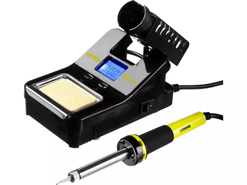
Soldering Station
But before you repair LED spotlights, chandeliers or lamps, you need to determine the cause of the failure.
How to disassemble an LED light bulb
One of the problems that a novice home craftsman faces is how to disassemble an LED light bulb. To do this, you need an awl, solvent and a syringe with a needle. The diffuser of the LED lamp is glued to the body with a sealant that must be removed. Passing carefully along the edge of the diffuser with an awl, inject the solvent with a syringe. After 2 ÷ 3 minutes, lightly twisting, the diffuser is removed.

Some lighting devices made without gluing with a sealant. In this case, it is enough to turn the diffuser and remove it from the housing.
We identify the cause of the failure of the LED light bulb
Having disassembled the lighting device, pay attention to the LED elements. Burned is often identified visually: there are burn marks or black dots on it. Then we change the faulty part and check the functionality. We will describe the replacement in detail in the step-by-step instructions.
If the LED elements are in order, go to the driver. To check the performance of its parts, you need to solder them out of printed circuit board... The value of the resistors (resistances) is indicated on the board, and the parameters of the capacitor are indicated on the case. When dialing with a multimeter in the appropriate modes, there should be no deviations. However, often failed capacitors are determined visually - they swell or burst. The solution is to replace it with a suitable one in terms of technical parameters.

Replacing capacitors and resistances, unlike LEDs, is often performed with a conventional soldering iron. In this case, you should be careful not to overheat the nearest contacts and elements.
Replacing Light Bulb LEDs: How Difficult It Is
If you have a soldering station or a hair dryer, this job is simple. It is more difficult to work with a soldering iron, but it is also possible.
Good to know! If there are no working LED elements at hand, you can install a jumper instead of the burnt one. Such a lamp will not work for a long time, but it will be possible to win some time. However, such repairs are made only if the number of elements is more than six. Otherwise, the day is the maximum work of the repair product.
Modern lamps run on SMD LED elements that can be soldered out of an LED strip. But it is worth choosing those that are suitable for technical characteristics. If there are none, it is better to change everything.

Related article:
For the right choice LED-devices need to know not only general ones. Information about modern models, electrical circuits of working devices will come in handy. In this article, you will find answers to these and other practical questions.
Repair of the LED lamp driver in the presence of the electrical circuit of the device
If the driver consists of smaller SMD components, use a copper wire soldering iron on the tip. A visual inspection revealed a burnt element - we solder it and select the one that matches the marking. No visible damage is more difficult. We'll have to solder all the details and ring them separately. Having found the burned-out one, we change it to a workable one. It is convenient to use tweezers for this.
Useful advice! Do not remove all elements from the PCB at the same time. They are similar in outward appearance, you can confuse the location later. It is better to solder the elements one at a time and, after checking, mount them in place.

How to check and replace the power supply of LED lights
When installing lighting in rooms with high humidity (or), stabilizing ones are used, which lower the voltage to a safe one (12 or 24 volts). The stabilizer can fail for several reasons. The main ones are excessive load (power consumption of the luminaires) or the wrong choice of the degree of protection of the unit. Such devices are repaired in specialized services. At home, this is unrealistic without the availability of equipment and knowledge in the field of radio electronics. In this case, the power supply unit will have to be replaced.

LED power supply
Very important! All work on replacing the stabilizing LED power supply is carried out with the voltage removed. Do not rely on the switch - it may be incorrectly wired. The voltage is disconnected in the distribution board of the apartment. Remember that touching live parts with your hand is life-threatening.
You need to pay attention to specifications devices - the power must exceed the parameters of the lamps that are powered from it. Having disconnected the failed unit, we connect a new one according to the diagram. It can be found in the technical documentation of the device. This is not difficult - all wires are color-coded, and the contacts are letter designation.

Plays the role and degree of protection of the device (IP). For the bathroom, the device must be marked at least IP45.
Article
Light emitting diodes are widely used in modern lighting fixtures. This is due to their efficiency and high reliability compared to conventional electric lamps. However, LED elements are not immune to malfunctions. You can check their performance in various ways, but the most accurate and simple method is checking with a tester. In this article, we will talk about how to test an LED with a multimeter, and what are the features of this procedure.
Testing LEDs in Continuity Mode
The multimeter is a universal meter that allows you to check the serviceability of almost any electrical device or item. To test a light emitting diode with a tester, it is necessary that the device be able to switch to the diode test mode, which is most often called continuity.
Checking the health of the LED with a multimeter is performed in the following order:
- Set the tester switch to diode test mode.
- Connect the test leads of the multimeter to the contacts of the item under test.

- When connecting the LED, take into account the polarity of its terminals (black probe measuring instrument connects to the cathode, and the red one to the anode). However, if the exact location of the poles is unknown, then there is nothing wrong with an incorrect connection, and the LED will not fail in this case.
If the probes are connected to the contacts incorrectly, then the initial readings on the tester display will not change. If the polarity is not reversed, the working diode will light up.
- The dialing current is of little value and is not sufficient for the LED to operate at full strength. Therefore, you can see the glow of the element by slightly darkening the room.
- If there is no way to dim the lighting, you need to look at the readings of the multimeter. When checking the working diode, the values on the instrument display will differ from one.
Visually checking the LEDs on the video:
Even a powerful diode can be tested using this method. The disadvantage of this method is that it will not work to diagnose the elements without soldering them out of the circuit. To test the LED in the circuit, adapters must be connected to the probes.

Sometimes the serviceability of a part is checked by measuring resistance, but this method has not become widespread, since in order to use it, you need to know technical specifications diode.
Checking LEDs without unsoldering
To connect the meter probes to the PNP connector, small metal tips must be soldered to them, for which you can use simple paper clips.
To more reliably insulate cables with soldered lugs, insert a PCB gasket between them and wrap the structure with electrical tape.
Through these simple manipulations, we will get a reliable and at the same time simple adapter, with which we can connect the multimeter probes to the contacts of the light-emitting diode.
Then the probes are connected to the contacts of the LED element, while desoldering the last of general scheme not required. Further verification is carried out in the same order as described above.
Let's give an illustrative example of checking the health of an LED without unsoldering it from the circuit.
Checking light emitting diodes in flashlights
When testing elements of LED flashlights, the device must be disassembled and the board with mounted LEDs removed from it. Then the tips, soldered to the probes of the multimeter, are connected with the correct polarity to the legs of the LED directly on the board.

The tester's switch is set to the dialing mode, after which it is possible to determine whether the element is serviceable by the reflected readings on the display and by the presence (or absence) of luminescence.
Checking the LEDs without soldering is also convenient because it allows you to determine the malfunction by measuring the resistance value in the circuit. So, when the LED is connected in parallel, a resistance approaching zero indicates a malfunction of at least one of the elements. Having received such results, you need to check each LED separately using the above methods.
On the video, checking the LEDs of the light bulb without desoldering:
Conclusion
From this material, you learned how to check an LED for serviceability with a multimeter. This procedure is not complicated at all, and, having an ordinary tester at hand, everyone will be able to check the performance of LEDs in household appliances.
Most effective method to check the LED for operability is to use a special device - a multimeter, which is otherwise often called a tester. The device is a measuring device that can perform several functions. You can select them using the knob located on the front panel.
Continuity testing
Every multimeter, no matter how expensive it is and which company it was produced by, must have a function for checking the LED performance. This is the so-called dial tone.
Before ringing the LED with a multimeter, it is necessary to set the tester mode switching knob to the dialing mode. Then attach the black and red test leads of the multimeter to the contacts of the tested device. Thanks to this test method, you can also determine how much power the LED has.
When connecting the tester, the polarity of the tested object must be taken into account. Its anode should be connected to a red probe and its cathode to a black one. If you connect the probes incorrectly, the device will not show anything. When connected correctly, the LED should start emitting light.
 When checking the diode for operability, it is important to take into account the following feature: the electric current of the tester configured for the dialing mode is rather weak, so it may not have any effect on the light bulb. The object being checked may be quite functional m, but will not glow due to insufficient current strength.
There may be another consequence of the weak current: the LED will start to glow, but its radiation will be so scanty that it will not be possible to see it in normal daylight. It is recommended to dim the external light before starting the test. If for some reason this cannot be done, you should pay attention not to the device itself, but to the measuring device, more precisely, to its readings. If it is serviceable, then the figure shown by the tester should be different from one.
You can even ring a very powerful diode with a multimeter. However, the disadvantage of this method is that it will not work to check the elements that are soldered into the microcircuit. To check the LED in the microcircuit, you need to use special adapters that are connected to the tester probes.
Check without desoldering
 To check with a multimeter without soldering the LED from the microcircuit, you can use small metal tips, the role of which can be played, for example, by ordinary paper clips. For reliable insulation of the wires to which the lugs are connected, a textolite gasket should be used. In this case, the entire structure must be wrapped with electrical tape.
After completing all these simple steps, you will get a reliable adapter., through which it is easy to achieve contact of the tester probes with the cathode and anode of the LED being tested for performance.
Also, without soldering from the microcircuit, you can check the diode for serviceability.... For this it is enough:
- Set the measuring device to dial mode.
- Connect the probes with an adapter to the contacts of the tested object.
- Check if the light is on or not.
As in the case of a regular dial-up, which is carried out without an adapter, you may have to turn off the external lighting or dim it in order to notice the dim glow of the device light.
The performance of light emitting diodes in flashlights
It is possible to check the efficiency of the LED in a small flashlight without much difficulty.
This check is carried out in several stages.:

Immediately after this, it will become clear whether the item being checked is serviceable. If he lights up, then everything is fine with him. If there is no radiation, then the LED is faulty.
 To test an LED with a tester, it is important to be able to distinguish between a cathode and an anode. In fact, the difference is easy to detect visually: the cathode is usually noticeably shorter than the anode. You can remember this: the word "cathode" begins with the letter "k", therefore, this contact is short. However, even if you connect a multimeter without observing the polarity, nothing bad will happen. The LED element will simply not receive current and therefore will not light up.
Instead of guessing each time you check which contact is “positive” and which is “negative,” it’s better to remember once forever. This will save time. It is not uncommon to measure the resistance to check if the LED is working. However, this method of verification is not very widespread, because before using it, it is necessary to determine the technical parameters of the device.
As seen, checking the performance of an LED using a tester is a fairly simple procedure... This will not take long. You don't have to make any physical efforts either. And the financial costs for such a check are practically negligible, since the used device is sold at a very low price.
Before using the LEDs, an important step is to first check the functionality of these devices. This issue becomes especially relevant when installing LEDs in hard-to-reach places. For example, when installing LEDs in luminaires located on street masts or industrial ceilings.
As with a conventional diode, the simplest method for assessing performance is to test the LEDs with a tester or multimeter. To do this, it is enough to connect it with the anode to the plus of the measuring device, and the cathode to the minus. To correctly distinguish between anode and cathode, it is necessary to remember that usually the anode lead of an LED is longer than the cathode lead. But such a "ringing" is possible only for such LEDs, which have a low operating voltage. For powerful ones with increased operating voltage, this method is unacceptable.
To assess the health of the LEDs, you can use the connector in the multimeter to test the transistors.
In this case, the output of the LED anode must be inserted into the hole intended for the emitter of the transistor under test (designation E), and the output of the cathode into the hole into which the collector of the transistor under test should be inserted (designation C for PNP). When the multimeter is turned on, a good LED will be on.
A more accurate examination of the LED is often required. This is especially true for high-power LEDs, the characteristics of which are designed to work with currents of hundreds of milliamperes or more.These LEDs can be backlit when "dialing", but when they are turned on in the operating mode at full current, they light up very weakly. Such a malfunction may be associated with a defect in the crystal. And this defect can be detected only with more thorough testing of the device.
How to do accurate performance testing?
 For more accurate testing of the LED health, in addition to the multimeter, an additional stabilized current source is required. Testing is done as follows:
- A circuit is assembled from a series connection of a stabilized current source, an LED and a multimeter (the current measurement limit in the multimeter is set at 10 A).
- In a stabilized current source, the rated current of the LED is set, the value of which is monitored with a multimeter.
- The power supply turns off.
- The multimeter is connected in parallel with the LED (the voltage measurement limit in the multimeter is set to 20 V).
- After switching on the current source, the operating voltage is measured on the LED.
- According to the data obtained and the current-voltage characteristic of the LED, given in the passport for the device, the compliance of the measured and rated values of current and voltage is checked.
- Based on the comparison results, a conclusion is made about the serviceability of the LED and the possibility of its operation.
When comparing the passport and measured basic characteristics of the LED, it is necessary to take into account:
- accuracy of current and voltage measurements;
- the fact that the volt-ampere characteristic of this type LED reflects the average dependence of current on voltage.
conclusions:
1. Before installing the LEDs, it is advisable to check their performance.
2. You can use a multimeter to pre-test the LEDs for good condition.
3. To thoroughly test LEDs, especially high-power LEDs, you must use a circuit that includes a multimeter and a constant current source.
A simple way to check an LED with a multimeter on video
CHECKING THE LEDS WITH A MULTIMETER
Now there is a lot of technology where LEDs are used and their field of application is very wide: from a simple flashlight to a car and even a searchlight.
Of the advantages of LEDs, we note that in an LED, unlike an incandescent lamp or fluorescent lamp, the electric current is converted directly into light radiation with practically no loss, the LED emits in a narrow part of the spectrum and its color is clear, and ultraviolet and infrared radiation is usually absent. It is also mechanically stronger than lamps and very reliable; its service life can be hundreds of times longer than that of an incandescent light bulb. And one of its few drawbacks is the price. But in the next couple of years, this figure will be reduced to acceptable prices.

More and more often we have to deal with the repair of all kinds of LED devices. This is where the problem arises. How to check the LED? The question may sound strange! It would seem that the answer is obvious: a multimeter. Those who have an ordinary multimeter know that they can check any diode, just
by moving the range switch to sound signal or just to test diodes.But this rule is suitable for conventional diodes and very low-power red and green LEDs (when checking, you will see them glowing weakly if the LED is working properly).And this option is not at all suitable for testing white, blue, and sometimes yellow LEDs, since their operating voltage is within 3.3 V.Of course, you can test the LED using two 1.5V batteries connected in series, but this is an unjustified complication. Now we are talking about a multimeter. Almost all modern digital multimeters there is a mode for measuring the parameter of transistors - hFE (h21E). For this, a special block is provided in the multimeter, where low-power transistors are connected. Here she is what we need.
If you take the LED and its anode output, connect it to the PHP block (PHP structure transistors) - to the E (emitter) connector, and the cathode output to the C (collector) connector of the same PHP block, then if the multimeter is on, the LED will light up.

It will glow at any position of the measurement mode switch and will go out only when the device is turned off.
This feature of digital multimeters will be used when testing LEDs. It is very simple to find out which of the leads of the LED has an anode and which cathode: the anode lead is longer than that of the cathode.
After some tests, one drawback emerged. To check the LED, you had to solder it, which is not always justified. It was decided to supplement the multimeter with modified additional probes for testing the LEDs directly on the board.
For the manufacture of this device we need: 1 -Standard tester probes with cut plugs. 2 -Double-sided textolite, two paper clips (ideally, it would still be nice to have an SMD LED as an indicator, but it was not available).Cut out a small rectangle from the PCB and solder paper clips to it on both sides to make a plug, probe wires and, ideally, an SMD LED as an indicator. No additional resistors are needed.Here's what we end up with:
The clips are very strong, spring well and ultimately stand securely in the multimeter's transistor block. The thickness of the PCB just corresponds to the distance between the holes of the transistor block of the device. The photo shows that the pins of the paper clips are not in the middle. This is done on purpose, now the textolite will still act as an arrow when connecting the plug to the connector of the transistors, so that the correct polarity remains on the probes.

As a result, we can now test any LEDs without soldering them from the board and without using additional probes or power supplies.
Well, to add a little information about you can download from our website good scheme and a description of this multimeter.Material provided by: A. KulibinSupplement from kkn8052 : Once a home-made logic probe was sold on the radio market, or it was almost handicraft, and so there was used an ordinary needle for the probe. a needle is taken and a 0.2 mm wire is wound on it, such wires already tinned can be found in an ordinary stranded wire, they are there in incredible quantities. This thin wire is wound on a needle, coil to coil, and then soldered with a soldering iron. Everything was perfectly soldered. Here it turned out that the needle is not stainless and not steel, but it is covered with nickel and everything is instantly soldered to nickel. I just poked it with a soldering iron and everything is ready right away. Thus, a probe is obtained. The contact is incredibly good. I redid the test leads for the tester, everything is fine, no complaints. Everything works very well!