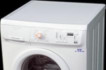
Someone had such an interesting film on TV late in the evening, and the wife constantly pressures that make the TV quieter, the child is asleep ?? What to do? Headphones with wires are not convenient, wireless is expensive to buy. But there is a way out.
I present to you wireless headphones on IR rays. More precisely a transmitter and receiver for headphones. The principle of operation is very simple, the transmitter is connected to an audio output on a TV or any other equipment. In the transmitter, the IR diodes are installed, the same as in the TV remotes, the transmitter converts the sound from the TV into IR signals that are received by the receiver.
You don't need to flash anything in the circuit, just assemble the circuit and enjoy.
Here is the transmitter circuit itself:

It consists of a small number of parts, it will not be difficult to assemble it. You can even not etch the board, but do everything with a hinged installation. The transmitter is powered by 12V, if it is less than, for example, 9V, everything will work, but there will be a little phoning in the headphones. The transmitter does not need to be configured, the main thing is to connect everything as in the diagram.
The transmitter board itself, after assembly.

The diagram shows 4 IR diodes for transmission, but I used only 3, there were simply no more. You can put one, but the more there are, the easier it is to catch the transmission signal. Connecting IR diodes and Photo diodes below in the photo:

The receiver It also consists of a minimum of parts, even less than the transmitter.
Receiver circuit:

The heart of the receiver is the TDA 2822 microcircuit. In stores it costs a penny.


The receiver is powered by 3-4.5V, from any power source.
The receiver board is quite compact.

And so, a suitable housing for the receiver was found.

All the filling fits there very well, there is a lot of space left.

It became a matter of nutrition. I thought for a long time what to adapt there and opted for batteries from a children's toy. As a result, it will be possible to simply charge the batteries, and not change the batteries.

I packed everything in the case, there was just enough space.

In the end, everything looks great.

Now it is the turn of the transmitter housing. I put the case as I had at that time. After all, the power will be external, from the power supply.


9V power supply.
All is ready. To check the performance of the receiver, turn it on, connect the headphones, point a simple TV remote control at it and press any button, clicks should be heard in the headphones, if they are, then the receiver is working.
Among the devices designed for remote control and control, devices using infrared (IR) radiation occupy a long and honorable place.
For example, the first infrared remote controls appeared in 1974 thanks to the firms Grundig and Magnavox, who released the first television equipped with such a control. Infrared sensors are widely used in automation.
The main advantage of infrared control devices is their low sensitivity to electromagnetic interference and the fact that these devices do not themselves interfere with other electronic devices. Typically, infrared remote control is limited to residential or industrial premises, and the emitter and receiver of infrared radiation must be in line of sight and directed towards each other.
These properties determine the main scope of application of the devices under consideration - remote control of household appliances and automation devices on short distances, as well as where contactless detection of the intersection of the line of rectilinear propagation of radiation is required.
Even at the dawn of their emergence, infrared devices were very simple to develop and use, but at the present time, when using a modern electronic base, such devices have become even simpler and more reliable. As you can easily see, even mobile phones and smartphones are equipped with an infrared port for communication and control household appliances by infrared channel, despite the widespread use wireless technologies such as Bluetooth and Wi-Fi.
Master Kit offers several infrared modules for DIY projects.
Consider three devices of varying degrees of complexity and purpose. For convenience, the main characteristics of all devices are summarized in the table at the end of the review.
- The infrared barrier is intended for use as a sensor for security systems, for sports competitions as a photo finish, as well as for remote control of automation devices at a distance of up to 50 meters.
The device consists of two modules - a transmitter and a receiver. The transmitter is assembled on a double integral timer NE556 and generates rectangular pulses with a filling frequency of 36 kHz. The timer has a sufficiently powerful current output in order to directly control the infrared LEDs connected to it.
A single analogue of NE556 is the famous integral timer NE555, which has been serving a whole army of radio amateurs for the development of electronic devices for many decades. Explore timer with 20 examples electronic circuits developed on the basis of this timer, you can use the kit-constructor "Classics of circuitry" of their series ABC of electronics. When assembling circuits, you don't even need a soldering iron; they are all assembled on a solderless breadboard.
The emitted signal is received by a receiver based on a specialized microcircuit, detected by a peak detector and fed to a transistor current amplifier, to which a relay is connected, which allows switching current up to 10A.
The infrared barrier, in spite of its simplicity, is a rather sensitive device, and allows it to work both for "transmission" and for "reflection" and requires the manufacture of hoods for the transmitter and receiver, eliminating the influence of reflected signals.
An example of the use of an infrared barrier in conjunction with the "Digital Laboratory" set from the already mentioned ABC series can be viewed.
- Is a light switch controlled by any infrared remote control.
The module allows you to control lighting or other electrical appliances using any button on the remote control.

As a rule, each remote control has rarely used or not used buttons at all. Using this switch, you can turn on and off the chandelier, fan, etc. with the same remote control from which you control the TV or music center.
When power is applied, the module "waits" for 10 seconds to receive a signal corresponding to the selected button on the remote control, and after this time expires, "remembers" the pressed button. After that, to activate the module relay, it is enough to press this button once; when pressed again, the relay will turn off. Thus, the "trigger" type control mode is realized. The module remains programmed even if its power is turned off.
It should be noted that the module "remembers" its last state when the power is turned off.
The device has a mode automatic shutdown load approximately 12 hours after it is turned on, in case the load is forgotten to be turned off.
The module relay can switch power up to 1500 W.
- The IR wireless control kit has its own remote control with 4 buttons and 4 control channels, 2000 W each.

Each of the 4 remote control channels operates in the "button" mode, i.e. the channel relay is closed while the corresponding button on the remote control is pressed.
With the help of the module, it is possible to organize reverse control of two collector motors, since each relay has one normally closed (NC) and one normally open (NO) contact with a common wire.
For ease of use, each channel is equipped with an LED that indicates relay activation.
The control panel of the kit is powered by the CR2032 element.

Load control with higher power for all considered devices can be carried out using expansion modules:
Up to 4000 W: Expansion module will do;
Up to 8000 W: Expansion module will do.
Infrared control modules
vendor code | Name | Supply voltage | Number of control channels | Maximum load power of one channel, W | Application examples |
Infrared barrier | 12V DC | Security devices; sport competitions; robotics; automation devices |
|||
Light switch | 12V DC; 220V variable | Lighting, ventilation, heating control |
|||
Wireless control kit | 12V DC | Reversible control of collector motors; 4-channel control of household appliances |
The remote control of the VCR, TV, music center or satellite receiver can be used to turn off and on various household electrical appliances, including lighting.
Do-it-yourself remote control will help us with this, the diagram of which is given in this article.
Description of the operation of the IR remote control system
The following mechanism is used for remote control of devices. Press and hold an arbitrary button on the remote control for 1 second. The system does not respond to a short press (for example, when operating the music center).
In order to exclude the response of the TV to the control of devices, it is necessary to select unused buttons on the remote control or use the remote control from the device turned off at this time.
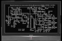
The schematic diagram of the remote control is shown in Figure 1. A special DA1 microcircuit amplifies and forms the electrical signal of the BL1 photodiode into electrical impulses. A comparator is built on radioelements DD1.1 and DD1.2, and a pulse generator is built on radioelements DD1.3, DD1.4.
The state of the control system (on or off the load) is controlled by the DD2.1 trigger. If the direct output of this trigger is log 1, the generator will operate at a frequency of approximately 1 kHz. Pulses will appear on the emitters of transistors VT1 and VT2, which, through the capacitance C10, will go to the controlling output of the triac VS1. It will be unlocked at the beginning of every half cycle of the mains voltage.
In the initial position, on pin 7 of the DA1 microcircuit, there is a log 1, the capacitance C5 is charged through the resistances R1, R2 and at the input C of the DD2.1 trigger, log 0. If the IR signals from the remote control go to the BL1 photodiode, on the contact 7 of the DA1 microcircuit there will be signals, and the capacitance C5 will be discharged through the diode VD1 and the resistance R2.
When the potential at C5 drops to the lower level of the comparator (after 1 second or more), the comparator will switch and a signal will be sent to the DD2.1 trigger input. The trigger state of DD2.1 will change. This is how the devices switch from one state to another.

Chips DD1 and DD2 can be used similar to the series K564, K176. VD2 is a zener diode for a voltage of 8-9 volts and a current of more than 35 mA. Diodes VD3 and VD4 - KD102B or similar. Oxide tanks - K50-35; C2, C4, C6, C7 - K10-17; C9, C10 - K73-16 or K73-17.
Setting up the IR remote control system
It consists in the selection of the resistance R2 of such a value that the switching takes place after 1 ... 2 s. If an increase in the value of this resistance leads to the fact that the capacitance C5 will not be discharged to the threshold voltage, it is necessary to double the capacitance C5 and re-adjust.
Capacitance C6 should be set in the event that the duration of the front of the pulse coming from the comparator to the trigger is excessively long and it will switch unstably.
If the used remote control does not allow you to control the device without interfering with the TV, it is possible to assemble a homemade remote control, which is a generator of rectangular signals with a repetition rate of 20 ... 40 kHz, operating on an emitting IR diode. Options for a similar remote control on the KR1006VI1 timer (
Having assembled the JDM programmer, we start looking for some simple scheme to repeat. Quite often these are trivial blinkers on an LED or a clock on LED indicators, but the first option practical application almost does not, and the second is often not suitable, not because it is undesirable, but because a radio amateur, especially a beginner or living in the outback, does not always have the necessary components (for example, a quartz resonator or LED indicators).
In the scheme proposed below, taken from the Iron-off site (http://aes.at.ua/publ/31-1-0-61), more accessible elements are used.
Photo sensor TSOP1738 was replaced by me with TSOP1736, but you can experiment with similar parts removed from faulty hardware.
The microcontrollers indicated in the diagram are flashed with different firmware - both firmware versions can be downloaded from the above site.
Any relay can be used for a winding voltage of 12 volts.
A little about the rest of the details, since the denominations of some of them are not read very well on the diagram:
C1 - 220 μF 25 V;
C2 - 220 μF, at least 10 V;
C3 - 0.1 μF (here a misprint crept into the author's circuit - the next capacitor, electrolytic, should have serial number 4);
C4 - 4.7 μF 10 V;
R1 - 330 Ohm;
R2 - 1K;
R3 4.7K;
T1 - BC547, KT315 or other similar transistors of the N-P-N structure;
LED - LED of any type and color you like;
D1 - 1N4148, 1N4007 or analogs;
Button - no fixation.
Stabilizer - any 5 volts.
A single-channel receiver module with a relay, for operation from any standard infrared remote control, provides remote control of any load via an invisible IR channel. The project is based on the PIC12F683 microcontroller and the TSOP1738 is used as an infrared receiver. The microcontroller decodes the RC5 serial data project coming from the TSOP1738 and controls the output if the data is valid. The output can be set to various required states using a jumper on the board (J1). There are 3 LEDs on the PCB: power indicator, transmission presence and relay actuation. This circuit works with any RC5 remote control from a TV, center, and so on.

Features of the scheme
- Receiver power supply 7-12V DC
- Receiver current consumption up to 30 mA
- Radius of action up to 10 meters
- RC5 signal protocol
- Board dimensions 60 x 30 mm

Although in recent times it has become fashionable to use a radio channel, including Bluetooth, it is not at all easy to make such equipment on your own. In addition, radio waves are subject to interference, and it is elementary to intercept them. Therefore, an IR signal will be preferable in some cases. Firmware, drawings printed circuit boards and Full description in English -