Main technical characteristics
Accepted TV systems: PAL / SECAM / NTSC, B / G, D / K, I, M.
Received frequency range: 45-169 MHz; 175-870 MHz.
Power supply: alternating voltage 100 ... 270 V, 50/60 Hz.
Tuning: 100 programs, automatic or manual search.
OSD menu: multilingual, including Russian.
Sound: MONO, stereo (from LF input), stereo from the air (A2 NICAM).
Rated output sound power 2 × 8 W.
External connectors:
- front: RCA-IN, headphone output;
- rear: - RCA- IN / OUT, SCART.
Additional features: the presence of sleep and on / off timers, there are child lock and "Eye" modes (dynamic change of image parameters depending on ambient light conditions). The installation of the "teletext" card is provided.
Power consumption from the network:
- 14 "picture tube - 80 W;
- 20 "picture tube - 90 W;
- 21 "picture tube - 95 watts.
Basic electrical diagram
The basis of the TV design is the chassis on which the TV components are located. The chassis is a horizontally located board with elements of a power supply, sweep, RF and sound paths. Teletext and stereo sound modules (NICAM standard) can be installed on the chassis as options.
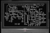
Consider the principle of operation of the TV according to the circuit diagram shown in Fig. 3.1-3.3.
Video signal processing path
The broadcast TV signal is fed to the antenna input of the TU101 tuner (see Fig. 3.1).
The tuner used in the above types of TVs is digital. It includes: a digital control circuit, a frequency synthesizer, analog circuits (radio frequency amplifiers, mixers, UHF). The tuner is controlled by the IC01 microcontroller via the I2C digital bus.
Rice. 3.1. Schematic diagram of the MC-84A chassis
The analog and digital parts of the tuner are powered by +5 V (pin 6, 7 TV101). The +33 V voltage required to form the tuning voltage is supplied to the pin. 9 tuner. This voltage is formed from the pin. 7 line transformer T701 and then goes through a rectifier (D743, C748) and a stabilizer (ZD102) to the tuner.
On the I2C bus, it is possible to select a sub-band, tune to television stations, and also provide APCG functions. The AGC voltage shaping circuit is part of the IC501 microcircuit. The AGC voltage level, which is generated by the circuit as part of IC501, comes from the pin. 54 microcircuits per pin. 1 tuner and is determined by the amplitude of the IF signal coming from the tuner.
The IF signal generated by the tuner is fed to the preliminary IF amplifier (Q120) and then through the band pass filter Z101, the already in-phase IF signal is fed to the pin. 48, 49 IC501. This multifunctional microcircuit performs the functions of UPCHI, UPCHZ, synchroprocessor, multisystem color signal decoder and video processor.
LG CF21D70... When you turn on the TV, after 2-3 seconds it goes into standby mode. The reason is the breakdown of the 2N4148 (150V) diode according to the D408 circuit. Already 3 cases in 3 months.
GOLDSTAR CKT-4905 The TV does not turn on. At the output, instead of 115 volts 40. Moreover, the voltage on the diode is normal, and after relay 40 The power supply works without additional overload sounds. The 115-volt diode gets very hot. When checking the secondary circuits, no suspicious parts are found. The capacitor C8075 160V \ 33Mkf turned out to be faulty. Checking the capacitance on the device showed that instead of 33 Mkf, only 0.23 Mkf, the leakage was 50 ohms. The defect is very common. I replaced the broken TDKS in TV LG: 154-375F, after which I observe a strange effect: service information (program number, menu lines) twitch vertically 2-3 cm, the main image is normal, if you reduce the SCREEN voltage on TDKS twitch stops, the brightness of the plot also affects. It turned out that the secondary voltage from the TDKS to the personnel supply was overstated - 29v instead of 24v. I put 3 diodes in series in this circuit and that's it.
TV LG CF-20D30 when turned on, the network button blinks with the LED on the front panel once and nothing more - the power supply unit did not start, there are no secondary output voltages. The culprit was the electrolyte in the STRS5707 strapping (it stands between the radiator plates of the STRS-ki, C = 4.7 microfarad * 50V), which lost its capacity to 1 microfarad.
Gold Star (LG) 21D16... The guys are overly clever in this model with stereo sound on an additional board and TDA2009A. In a number of boxes, after six months or a year of work, a problem appears in the form of a hoarse (farting) and weak sound. The most optimal solution to the problem, without replacing the microcircuit, turned out to be a hinge of 2 - 3 MΩ resistors between the input of the first and second TDA channels and + 12V.

Goldstar CB-28C22X... Narrow horizontal stripe. Penetrated 2-zener diode 24v, charred R304. After replacing the zener diodes, the strip remains, R304 heats up. Replaced out. to. frame. development, TDA8350Q- the resistor has stopped heating up, but the strip is still. (The desired scheme is at hand, as always). After analyzing the circuit, I found that 2 power supplies come to the cadre ms: for 4 and 8 legs. On pin 4, D702 is broken, FR702 is open. After the replacement, the TV worked. (On the Internet, the dock on the TDA8350Q can be found on the prodelectronics website.)
TV Goldstar CF-21E60B... An external symptom of a malfunction - a few minutes after switching on - there is no image (dark screen) and sound in the presence of a raster, there is no response to commands from the remote control (controlled from the TV panel), and later - video synchronization failure and spontaneous entry into the duty officer mode, and after a while the functions are restored, and everything is repeated. Fault - in the LG8534-13A processor, part of its circuit is analog adjustments, switching on - off, the decoder of remote control commands fail during warming up. Treatment - secretly ¦125, without soldering, applying a layer of CBT and applying a copper plate to the size of the case on top, fried with a 65 W soldering iron until the solder on the plate stopped hardening (8-15 sec). Second successful recovery.
LG CF-21K49 based on MC994A chassis. The symptom does not turn on or has a narrow vertical stripe on the screen. The capacitor C411 334 / 200V is most likely to be replaced.
LG CF-20D30 (Chassis: MC64B)... No reception on the upper meter sub-band. The malfunction came to light quite unexpectedly. The main one (on which there was a call) was: the network power button (white, dear 150 rubles) deteriorated. After replacing the switch, it turned out that there was no voltage to turn on the HB sub-range (instead of 12V, only about 5V). Switching voltages are supplied through transistors, a cursory check of which showed that everything is OK. Everything was rounded off, as it were, on a tuner (ordinary eight-legged). But I have never met such a defect. The doubts turned out to be correct. After soldering the little things around the output of the NV tuner, it turned out that the Q181 2SA1266 (p-n-p 50V 0.15A) transistor on ohms rings as normal, and on kOhms it has R (b-e) arr. = 150 kOhm. He then put 12V on the output of the tuner.
LG-CF21D79 TV, oversaturated color image b / w no, as if there is no luminance signal. Replacing the TB1238BN video processor did nothing. The SECAM TA1275AZ microcircuit turned out to be faulty.
TV LG20 on MS-84A chassis... The defect may not be widespread (met once), but it seemed interesting to me. Slowly responds to commands, poorly configurable and does not remember settings. The service turned out to have all the settings at zero, but after entering the proper initialization modes and exiting the service, everything repeated itself. Replacing the memory gave nothing. It turned out that two out of eight resistances in the ceramic assembly showed ~ 2.4 kOhm instead of 4.7 kOhm.
Problem with LG chassis MC-019A. The TV does not come out of standby mode if you measure the line power - about 70 volts. First of all, see C820 220 MF 160 B, most often one of the capacitance leads is cut off, the leads are molded at a very sharp angle.
LG CF-21D70 (Chassis: MC-64A)... When turned on, it goes into standby mode, and then completely goes out. The analysis showed that when the mains voltage is applied, the output voltage + V gradually rises to more than +160 V (the norm is + 125V), and then the internal protection is triggered and the power supply is disrupted. Analyzing, I identified a defective electrolyte C824 4.7μF 50V (leakage, drying out or an increase in internal resistance to high frequency), installed between 4 pin. optocouplers IC801 and 7 pin. STRS5707. What pleases me is the timely internal protection, which did not allow the murderous + B = 160-180V to roam.
TV Gold Star CF21E20 chassis MC-41A The sound is missing. I quickly found that the volume control signal is almost zero, you solder the control output of the GS8434-16 control processor (3pin) - it yells at full speed, there is no sound in AV mode either, it would seem that everything is clear, you need to change the percentages - it's not such a rarity. .. But after the replacement, the situation did not change, flashing the USB flash drive to a known good one did not bring any result either. I had to start thinking .... I take out the antenna, after 10 minutes the TV turns off, well, that's how it should be. I leave it with a signal from the air - after the same 10 minutes it turns off - it is clear that there is no SOS signal (here it is designated as ID-17pin of the processor) - a constantly high level. Unfortunately, the stereotype of thinking worked here - I apply a low to this input, but the situation does not change, and in the mode from the video input there is also no sound ... if the station signal is lost, the level changes sharply. Here, the signal is pulse - SSC pulses are used. Transistor Q06 - shaper of the signal ID "drip" transition K-B, there were no pulses at the ID input. In SAMSUNG TVs, when the "sweet couple" failed and the R2M protection was broken, TDKS- was punched in the upper part, next to the high-voltage wire outlet, a mother-in-law formed about 5 mm and a spark was emitted from it into the core. Here the advice on the restoration of TDKS helped a lot - I drill a couple of mm deep into the crack with a large drill and fill it with white auto-sealant, after 3 hours I can turn it on. Thus, 2 transformers per week.
On tv LG-21D70X when you turn on, switch programs, information about the settings is not saved. After pressing the network button, the TV turns on to LINESVC mode, from which it switches to normal mode after pressing the TV / AV remote control button. After replacing the 24С02 memory and turning on the TV again switched to the LINESVC mode, then after pressing the TV / AV button on the remote control, the TV switched to normal mode with the restoration of the settings saving functions. No additional steps were required to "flash" the memory chip.
GoldStar and LG TVs before 2000... Tuner problems, does not remember settings, etc. It looks like the tuner is out of order. Solder ground contacts in the tuner.
Tv Goldstar CF20A80Y... When turned on, the sweep is heard, but there is no sound or raster. The fault lies in the m / s D402 (7809) made by KIA. It stands together with D401 (7812) on the same heat sink, not far from TDKS.
Gold Star CF-29C44 When turned on, the TV goes into protection. Replace the position number IC7P on the PIP board KREN 78L08. Almost all malfunctions in these models are associated with this KPENka.
GoldStar CF-21D60B. No sound. I got the 2nd TV with such damage. The output for adjusting the sound on the 3rd leg of the LG8434-03C processor is faulty. Our processor costs ~ 800r. If the client is satisfied with the sound, you can start to adjust the contrast of this processor. Set the contrast to the optimal one at your discretion. The only inconvenience is the volume control via the menu.
LG CF-20D60... Does not turn on, when measured in the power supply, it starts up. Replacement of the 4.7mFx50V tank is required (located in the alignment of the 5707 radiator).
LG CF-21D70 Spontaneous transition to standby mode. On different channels in different ways, on some after 5 minutes on others after 10 minutes. Try to replace the electrolyte of position C408 with a nominal value of 160V1mF, it shrunk down to 0, and there was also a leak in the additives.
LG CT-29K37E. When you turn on the relaxation of the power supply, it enters the operating mode after 5-6 on-off attempts. It is necessary to replace the C808 (100.0x35V) in the power supply, which is assembled on the STR-F6656 microcircuit.
LG CF21D33 - does not turn on... + 185v = short-circuit to the ground - change TDA6107Q (by the way, there was a recently defective batch of these ics in Promelectronica with the number 3 in the lower right corner)
The broken D5072 quietly picks. change and get a heartbreaking whistle !!! (What were they fighting for?) It turned out that the Korean saboteurs had smeared the OS with a new "super-closure glue" from inside the OS. But nothing, we are not proud people - we remove the OS, wash the place of the short circuit. with the purest Russian alcohol, we move apart the turns, put electrical tape - and everything is in place.
GoldStar SF-14A90B a few seconds after switching on, the screen turned bright white. The KIA7805 stabilizer (5 V), which is on the processor's power supply, turned out to be faulty; during these few seconds it raised the voltage at its output to 7 volts.
Supra CTV1485 MC-41A chassis, aka Goldstar GF-14/20 / 21A80 MC-41A / B. In SEKAME there is no blue color, in PAL everything is OK. In SECAME, the blue B-Y core circuit L504 does not react to rotation. Do not rush to change the TA8750AN microcircuit, swap the L504 and L502 circuits connected through capacitors to pins 35 and 29 of the TA8750AN. In my case, after rearranging the contours in places, everything worked, obviously, the soldering of the legs (inside) of the contour affected, after which a small adjustment of the contours is required.
LG CF-21F89 MC994A chassis Symptom - turns on for a few seconds then goes to st-by. During the turn-on time, the line transistor manages to heat up. Shorted the line coil in the OS.
LG CF20F30... The fuse is lit. Broken diode bridge and IC802 STR5707 microcircuit. The bridge was soldered from the KD105's, I bit off 1 and 3 pins in the microcircuit, turned it on, there are start pulses on the 4 leg. I suspended the KT872A transistor (k-1n, b-3n, e-2n) on the wires, turned it on, it works. I put the tr-r on a suitable radiator.
LG CF-21D70 chassis MC64A... Spontaneously chaotically goes to the "duty room". Regardless of the operating time, heating or cooling. Replacing the processors and memory did not give any results. As a result of a long search, the defect was nevertheless identified - C408 1mkfX160v shrunk in the Q401 circuit (the pre-end of the line). B.P. does not start on these TVs. - drying out of C824 4.7mkfX50v in the optocoupler circuit.
GOLDSTAR is built on TDA3562A - Dark screen. Reason C -10mF / 250V, filter + 180V
GOLDSTAR CKT9905 - Faint image, + 112V is normal, and the supply voltage of + 180V video amplifiers is overestimated to + 270V - Defective C806 (47mF / 160V)
GOLDSTAR CKT9582 - White raster with reverse beam path - leakage of the Q906 transistor (BF421).
LG CF-20K51KE Breakdown of the Q402 D5702 line transistor on the case, with burnout. After the replacement, a new one flew out in a second. Replaced Q402 with BU2520DX, they are more reliable. A thorough check of the strapping did not bring any result. Disconnected one output of the lowercase coils of the OS and briefly turned on the TV. The screen lit up with a strip. I switched it on for a short time with the OS. The screen lit up with a compressed screen. The transistor remains intact. Replaced the OS. The result is positive. I did not find any defects in the broken OS.
GOLDSTAR 21E60. Does not turn on. Broken line transistor, TDKS and turn-to-turn circuit in the deflecting system.
LG CF-14G20R. Weak sensitivity. There is interference and noise in the image. The IF filter of the K6265K radio channel was to blame for this disgrace.
GOLDSTAR 21Е40. No high voltage. The power supply unit is working, there is sound. The amplitude of the horizontal scan trigger pulses on the basis of the SR pre-output transistor is small. At the 37th leg of the video processor, the voltage is 0.4 V. Reduced resistor R524 from 3.9 kOhm to 2.4 kOhm. The voltage increased to 0.57 V and its amplitude became enough to turn on the transistor.
ELEKTA CTR-1495EMK, GOLDSTAR CKT-4442B, CKT-9322B. Chassis PC-05X2... (There is no image (it can flicker vaguely), the screen is gray! There is sound. One of the reasons for this defect is the failure of the video signal switch, the microcircuit (GL3820, aka TEA2014A) is located on the video input board.
ELEKTA CTR-1495EMK, GOLDSTAR CKT-4442B, CKT-9322B. Chassis PC-05X2. Defect - there is no color image in the SECAM system. A fairly common reason is the SVC1 trimmer capacitor (next to the quartz resonator) in the SECAM-PAL transcoder circuit.
ELEKTA CTR-1495EMK, GOLDSTAR CKT-4442B, CKT-9322B. Chassis PC-05X2. The TV cannot be tuned or the setting is lost. Perhaps it is enough just to solder and unsolder the tuner. At least there was a defect.
ELEKTA CTR-1495EMK, GOLDSTAR CKT-4442B, CKT-9322B. Chassis PC-05X2. The TV does not turn on, there is no indication. The standby power supply transformer often fails. TP-8-3 is quite suitable, or similar for power supply of a 12 volt source. However, there was a case when the standby power was on, it turned out - a ring break KRENKI IC2 (7805) :)
ELEKTA CTR-1495EMK, GOLDSTAR CKT-4442B, CKT-9322B. Chassis PC-05X2. There is no image, the screen is dark green, "Lokhi" are visible, there is sound. The reason is the drying of the air conditioner in the power supply circuit of the video amplifiers (the voltage dropped right down to ... 119V, instead of 180-190 set! The screen may be completely dark (the power supply of the video amplifiers in that case was about 160! Volts).
ELEKTA CTR-1495EMK, GOLDSTAR CKT-4442B, CKT-9322B. Chassis PC-05X2. The screen is brightly white (or gray), brightness, etc. is practically impossible to adjust, the image only skips when you turn on the TV. Most likely this defect is a feature of color blocks with the ABB scheme. The cause of the malfunction is most often the video processor or transistor A1015 on the CRT board.
GOLDSTAR CF-20E20B When the TV is turned on, there is no raster and sound, there is high voltage. Fault: stabilizer IC402 (KIA7809)
LG CF-20F30 chassis MS-64A switches itself off to standby mode from 10 minutes to an hour. The entire board was literally "plowed up on elephants and camels", only the percentage of management was not affected due to its high cost. The reason for the shutdown of the LG8634-16C processor at pin 20, through the ABNORMAL protection bus, is the loss of capacitance of the capacitor C408 1μF * 160v in the primary power supply circuit of the TMC.
Goldstar LG CF-14/20 / 21A80V Does not leave standby mode. When the command to turn on is given, the voltage tries to rise and immediately drops to the value of the standby mode. Replace SE120N. Sometimes the power supply unit does not start. Solder the starting circuits.
LG CF-21F3. Immediately after switching on, it goes into standby mode. No Vsync on processor. Fault-break R15 4.7k
LG, CF-21F39, 2 years old. When transferring from standby to working, a burning smell appears and the TV goes back to standby. Open the lid and turn it on. There is smoke on the left side of the OS. On the inside, a breakdown is detected between adjacent windings. At the junction of the OS case separated by a plastic rib. The insulation is burnt on 3-4 wires on each side. It is necessary to carefully dissolve, remove the "coals", lay the wires in the cambric and fill with sealant. Interestingly, after 1.5 months the client complains that it is the same again. The smell appeared and turned off by itself. I remove the OS and find the same breakdown only now on the right. But this is already a topic for thought. As it is written on the TV cover: made in Ukraine from LG components. On the deflector we read: Planzhuan OPC 29-90-54. Made in China. But there is one more thing. Rubber wedges, which are placed under the OS, (which are usually 3 pieces and stand at an angle of 120 degrees) there are 4 pieces. Two vertically and two horizontally - exactly under the breakout point. It seems that rubber is not conductive either, but it may be bad heat dissipation, etc. Or the Chinese are driving marriage. Life will show.
LG CF-21D33E, the MC-84A chassis is similar to the breakdown of the deflection system Pianzhuan QPC 29-90-54. Assembled in Russia. When trying to replace the OS, large dilutions from the top and from the bottom. Breakdown occurs in two places where the turns from the two coils are closest, located along the horizontal axis. At these points, the turns are additionally fixed with a brown compound. It is through it that the closure beats. After removing the "coals" and the compound from the opposite side, routing the turns, and pouring hot melt glue, the OS started working. The mixing has improved in the best possible way.
I confirm this defect. Two TVs in a week. Wasp Pianzhuan QPC 29-90-54. The TV set is assembled in Russia. We couldn't find another OS. Correction is not output. Restored old OSKs!
GoldStar CF-14A74Y chassis МС41А after a thunderstorm, STR-S6707 and an optocoupler TPL721 flew out. After replacement and when checking b / p. to an external load of 60W, it worked fine. When the TV is turned on, the 112V channel is set to 85 and 90V, i.e. voltage jumps from 85 to 90 and vice versa occur with a frequency of approximately 3-6 seconds. At 85V, the screen is horizontally compressed and the white screen, and at 90V, the TV is normal, but the buzzing changes in the speakers and the line transistor heats up. Defective, the SE110 microcircuit turned out to be (it turned out that the reason was in it after connecting an external load of 150W to the power supply unit).
GoldStar CF-21E60B Image distortion, lack of luminance signal, color irregularity. Replacing the TA8750 and the TA8690 video processor, soldering the tuner did nothing. Voltage 12V and 9V are normal. Faulty IC201 LA7222 - video input switch
LG (I don't remember the model) with a 24С02 memory chip. If, after switching on, the volume is adjusted with the buttons on the front panel, then it is adjusted as follows: 0-50-100-mute, if you turn it off into standby mode and turn it on, it fills with white, the protection is triggered. Replacing the memory chip eliminated all faults.
Defect - no frame scan in devices: LG CF-20E60K chassis MS-64A. Breakage of the resistor R311 2.2 ohms.
Goldstar CF-21D10B There is no picture or sound, no noise, the screen is dark. Almost like in secrets No. 487 and No. 949, but - service info is displayed (menu, regulators, channel number, etc.) Fault: in this case IC401 (KIA 7812) Located on the same heat sink with D402 (7809), not far from line transformer.
LG CF-20K50E chassis MC-84A. Stands in the duty room and does not turn on either from the remote control or from the TV panel. It turned out to be one 4.7k resistance in the ceramic assembly near the control processor in an open circuit. I hung a similar resistor on the other side of the board: the box worked, but the raster was compressed vertically and shifted to the left. I didn't go into the service, changed the memory, the raster became normal.
GoldStar CF-21D60. The raster glows weakly, there is no image, there is sound. The amplitude of the V-Syng pulse at pin 2 of the processor is small ~ 1V. The reason is the punched zener diode ZD01 (5V1).
Goldstar CK-20A80. No picture, sound, OSD, video amplifiers are locked. Sometimes he doesn't even want to turn on from the duty room. Defective m / s EPROM (** 24С04). We solder clean and that's it.
LG CF-20F60. Received from another workshop with a diagnosis - defective processor. The device behaved in a rather original way: at first it started to work, after about five minutes it hung up and did not want to work any more during the day. Having rested for about twelve hours, I began to work again, hung up, and everything was repeated anew. Three resistors in the AR02 assembly turned out to be faulty, two of them were connected to the I2C bus pins of the processor, and the resistor values changed not upwards, as is most often the case, but downwards. Instead of the prescribed 4.7 kOhm, it became 2: 3 kOhm. For reliability, it was necessary to replace the entire assembly with ordinary resistors.
GOLDSTAR CF-25C36X. Defect - there is no picture and sound, there is weak noise on the screen. Suspicion first fell on the TDA9808 (radio channel), but the reason was IC182 KIA7805 (5-volt power supply TDA9808) - instead of 5 volts it gave out 3.
GOLD STAR CF-29C32J Does not turn on (after a thunderstorm). Break through tr-r Q301 2SB988Y replacement with 2SB1294. TV did not turn on, there is no starting of the primary circuit. R811 470k break after replacement started working.
LG, MS-64A chassis, power supply unit based on STR-S5707 assembly. PSU does not start. Leakage in the C820 220 uF, which is on the 9th leg of the assembly. The capacity showed normal and did not reveal itself when dialing a digital tester. The voltage on this leg was 7.2 V (instead of, as it turned out, 7.9 V).
LG modelCF-21K50E. Defect - there is sound, there is no picture, the screen is dark. At the autopsy, it turned out that there was heat, the voltage on the cathodes too. With an increase in the accelerating voltage, a bright narrow horizontal stripe appeared. The faulty LA7830 personnel microcircuit and a 1Ω resistor for the power supply of this microcircuit. The microcircuit flew out due to an increased voltage from the power supply (145 volts). The reason is that the electrolytes in the strapping of the power supply microcircuit (STR-S5707) have dried up. After replacing the electrolytes, the power supply unit began to produce 115 volts.
Goldstar CF-20A80V. The power supply does not start. Before the breakdown, the TV did not start well and turned off on its own. Soldering of the annular crack of the TPI outlet did not help anymore. At 9k STRS6707, supply voltage = 0. (start circuit). The 9th input of the microcircuit turned out to be in the leak.
GOLD STAR CF-20D60B. There is no color in PAL, although the screen displays the inscription: AUTOSYSTEM PAL. At the output 40 ms. IC501 TA8690 instead of 4 volts only 2.6. Reason: broken pin 33 (SECAM-ID) ms. IC01 GS8334-16A. There was no need to change the percentage - it was enough to disconnect the defective output from the circuit.
GOLD STAR CF-20D60B. There is no color in PAL and on the screen there is an inscription: AUTOSYSTEM SECAM. At the output 40 ms. IC501 TA8690 to PAL voltage 0.78 V. Faulty TA8690.
GOLD STAR CF-20E20B. Another addition to secret 509. Red predominates in SECAM. Faulty capacitor built into the circuit L502 E16A (R - Y). The defective one had to be broken out and replaced with an external one by 100 pF with a slight adjustment of the contour.
GoldStar CF-21D70R spontaneously goes into standby mode at different intervals, protection is triggered along the "ABNORMAL" circuit. Defect detected - capacitor C408 1.0 x 160 V.
LG-CF-20D70K Returning to the secret 415. Degradation of the C824 capacitor in the power supply unit (4.7 * 50 V) initially leads to difficulties with turning on the TV, but our people are stubborn. Multiple on-off TV turn on. And in the end it will all end with a breakdown of the power MCX STR-S-5707. This malfunction becomes typical for LG, along with the operation of the protection due to a malfunction of the capacitor 1.0 * 160v in the preliminary cascade of lines.
GoldStar CUT9322 chassis PC-05X2 (with a "flat picture tube" in the form of a removable glass). Fills with milk, the image is not visible. Replacement of TDA3562A. All the same, the effect remained, although a faint image in the negative began to break through. When the probe touches the 8 pin TDA3562A, a normal image appears. Conclusion - knocks down a constant through the capacity C514 0.22mF x 50v. The replacement helped, but not for long. The next time it was turned on, the effect was repeated. Enumeration of containers of different quality gave nothing. A new conclusion - for the TDA3562A microcircuits of the last years of release, the input impedance at the Y input (8 pin) has been changed. I put this input with a 1.5 mOhm resistor. Everything works fine. An additional check of the previously soldered TDA3562A confirmed that it was killed just at the Y input. A rare coincidence of 2 simple defects leading to pathological consequences, which some masters call a "drum".
GOLD STAR (LG) CF-14E20B chassis MC-41B. Lights up red (indicator DR), does not respond to buttons, + B = 43V. The reason is X01 (for some reason, it stood at 3.6MHz). According to the 4 MHz scheme, since failed - put 4.43.
GOLDSTAR (PC04A) 1). The replacement of C807 does not turn on in the operating mode 2). MC41V chassis is not adjustable, the sound is not configurable, programs are replaced by ROM. 3). No sound replacement Q06 adjustment L508. 4). No setting of the first range setting L508, 507.5). Frequency is leaving the replacement of the m-controller. 6). No Y-signal replacement LA7222. 7). Understated voltage replacing ZD811 with 7.5V.
GOLDSTAR CF-21E20B and other MC-41B. With warming up, it turns itself off, the DR indicator may blink. You can turn it on only after a while. If at first you do not discharge the filter and touch the 5th leg of the T802 (there is an annular crack), then you can burn STRS6707. One device "tore" just when removing the board - while putting it on the table (before that the TV worked - but waited for self-shutdown ...). It is possible to start up after replacing the STRS6707 only through a lamp of at least 300W (weaker ones flash due to the rapidly growing consumption current after a few seconds).
GOLDSTAR CF-21C22X MC-46A. Burnt out when switched on. The DR indicator is shining, when it is switched on to the working one, it goes out. For a moment, high and all other stresses appear (without reaching the norm), and then they fall. When TESTING the horizontal output stage with lowered + B = + 15V - impulses without distortion, may be slightly underestimated, the current is normal. BP without suspicion. I would have suffered for a long time. But I hung up another OS and the Miracle TV turned on with a narrow chaotic raster. Then the smell of burning was heard. Only a long thorough examination of almost ALL parts of the SR helped. The culprit was C401 434n \ 200V. It broke through under voltage and lost some of the capacity. It was cracked, but it was not noticeable in the board. I think testing would not help understated + B = + 15V, but a gradual increase in + B to the nominal. But there was no source and it would be necessary to take measures to limit the current - so as not to burn the test generator itself.
Goldstar does not tune channels on the TA8690 video processor. For those who were tuned, the tuning went. The AFT circuit did not work on the TA8690 processor after replacing the processor, it returned to normal
GOLDSTAR CKT9905 Fault: after turning on, after 5-10 minutes, the TV turns off, while the indicator panel went out. After analysis, suspicion fell on the relay on - off the power supply of the output stage. When a jumper closes the working contacts of the relay, the TV worked normally. After replacing the relay, the TV worked again.
LG CF-20F89. Chassis MC994A. Fault: does not turn on. Power supply for STRF-6707A (not to be confused with STRS-6707). Basically, no<подводных камней>... The chip itself is to blame. But a careful dialing of its conclusions with an ohmmeter did not reveal any differences from a serviceable one. The board has been removed from the TV. After replacing the microcircuit, the power supply unit started up, but after switching from standby to operating mode after five seconds. went back to standby. Not right away, but I guessed to connect the deflector. It turned out that without her TV does not come out of<дежурки>... This is still nothing. On some copies of Funai without a connected deflector, a line transistor knocked out.
LG CF-21S10E There is no frame splitting, we change the TDA8351 personnel microcircuit. We get the image compressed from the bottom to half of the screen, we change the TDA 8842 video processor, the image is normal, but there is no need to rejoice, everything can be repeated, but the TDKS 6174Z-8005A is to blame for this disgrace. At times it breaks through.
LG CF14E40 no setting replace -TDA8362-5
Goldstar on TDA4601 When you turn on the TV, the Q801 BU508D immediately fails. On TV, there is no start-up on the bulbs, but you can hear the generation in the TPI. The power supply for 9 n TDA4601 is understated, on the basis of BU 508 there are pulsations of an irregular shape with interruptions (i.e. Rectangular pulses of normal shape ot.) Replace C 801 10X16V. In case of failure of the Out TR, check MANDATORY R 270 Kom (with the number of TR through the TPI winding on 4-leg 4601). There is no start, but sometimes it can turn on, check 12V (power supply 4601, 9-leg - must be 12V to start)
Goldstar on TDA4601 comes out periodically with a horizontal transistor (42-cm kinescope), the B + power supply is 140v and is regulated upward. Check by desoldering the resistance R805 coming from the 3-pin TDA4601 on the B + regulator (should be from 6k2 to 12k) in this unit has increased to 16k.
Goldstar CBS-6081 Very bright glow of the raster, it is not possible to reduce the brightness control and Screen on the TDKS, by replacing it, check the BF421 on the kinescope board.
Goldstar CF-20D60B, chassis MC-41B When turned on<цыкает>PSU on STR-S6707 and does not start. Synchronously with<цыканием>PSU flashing LED on the front panel of the TV. Defective zener diode ZD811 6.8v in the KTD2092 base.
LG - CF-20D73 (MC-84A chassis). Apparatus after a thunderstorm. When the TV was brought to me, the processor reset chip (KA7542), the 7805 stabilizer was soldered there, the SE115 was soldered in the power supply unit, the jumper for the video amplifier power supply (TDA6107Q) was soldered, the line transistor (D5702) was soldered. I loaded the power supply with a light bulb - it works (put 115 at the output). By the way, when you turn on another light bulb instead of the fuse, it starts, then the lamp, which instead of the fuse, gradually heats up and the power supply unit is cut off. And without her, everything is OK. I sealed the power jumper to the video amplifier, put the KREN-ku, a horizontal transistor for testing (BU208), cut the horizontal scan through the lamp - it lit up - the shortcut in the lowercase. Disconnected the video amplifier - no short circuit. It turned out to be a breakdown in the power supply of the m / s video amplifier (6 ohms). The processor (LG-8838-07D CXP86441) also turned out to be dead (breakdown on the Reset 18 Ohm leg). The LED and diode, which is in series with the LED, also burned out. The LED was supplied with a suitable size, the diode was KD521. Replaced the processor, video amplifier, put the D5702 line transistor, reset chip. The TV started up, but instead of an image - a white (with a pinkish tint) screen with reverse lines. The indication on the screen is present. Replaced the video processor (TDA8842). An image appeared, but filled with white, and with LOCH-s. Reduced accelerating - the image is normal (low frequency). Does not remember settings - memory is not defective (24C04). No channel reception - the tuner is faulty (TV8PSB02D 911A290E). Inside the tuner, I found two burnt tracks. Soldered jumpers. Bad reception appeared only on the 1st band. Replaced the tuner with 6700VPF016A. Remote control does not work - IR receiver is faulty. I put the IR receiver and the reset chip from the VCR - they work fine. I removed a small pink spot on a blue background in the center of the screen by twisting the magnets on the neck of the picture tube. And the lightning hit the antenna - the mass track from the tuner to the arrester with the power wires burned out, and another track near the tuner. In the service, I adjusted the AGC, geometry, did not touch the white balance. Entering the service - press the OK buttons simultaneously on the TV and on the remote control. To switch the menu in the service, you must press the yellow button on the remote control. Since there was no such in my native remote control, I used the Chinese universal remote control.
LG CF-21D70 (Chassis MS-64A) - in dezh. the mode turns on. When switched to operating mode, there is a very loud and spectacular "shooting" in the TDKS. Sparks fly in all directions. The TDKS type 6174Z-8004B is faulty. Its cost is $ 18-22. On the schematic diagram of the MS-64A chassis, the type TDKS 154-375F is indicated for the 21 "diagonal, the cost of which is $ 8.5. I installed the 154-375F without any structural and fundamental alterations. The TV is working. Geometry is normal. Configured SCREEN and FOCUS But there is a drawback - the screen is rather blue with blue reverse lines.As a result of the shots of the line transformer, Q514, Q513 and Q512 (2SA1266Y) in the video amplifier failed. -375E. Sellers also offer as analogues 154-194D ($ 10) and HR7906.)
LG CF-21D70 (Chassis MC-64A) - When you press the "Network" button, the indicator of the bowl. mode lights up for 2-3 seconds and goes out. The voltages from the power supply unit, when the "Network" button is pressed, have nominal values for 1 second, then they smoothly decrease to 0V for 1-2 seconds. "Network" should turn on in standby mode). The "Network" button is faulty, which supplies power to the TV only while you press it with your hand. The owner of the TV said that the TV was almost always in the bowl. mode, i.e. the network button was rarely used.
GOLDSTAR CF-21E20B chassis МС-41. Malfunction titles, which usually run at the bottom of the frame, are doubled so that it is impossible to read them, the picture itself is of normal quality. I connect the test signal generator, turn on the grid on the video input, everything is fine, and on the HF through the antenna socket, a strong repetition of vertical lines is clearly visible, it is clear that the malfunction lies in the radio channel. In the end, the malfunction was localized in the K2559 SAW filter, replaced by K2550.
Goldstar CF-20F60. The TV immediately turns on in operating mode, bypassing the standby mode. The voltage from the power supply unit is too high. The optocoupler IC801 is faulty.
Goldstar CF-21C22X chassis MC46A The power supply is assembled on STRS6707. In operating mode, the TV works without remarks, but when the TV is switched to St-by mode, clicks are heard from the speakers, the frequency and volume of the clicks can change, then after some time the TDKS starts to squirm in time with the sound, that is, it tries to start. The LED lights up normally .. I measured the voltage in the power supply unit along the line in the St-by, it gave out all 80 volts, but should give out about 40 volts, that's why extraneous sounds appeared in the St-by. The capacitor in the power supply unit is faulty, 10 μF per 100 volts in the secondary circuit, for the optocoupler control.
LG KF-21P10 When you turn on the white screen across the entire screen, the reverse path of the beam, the TDA6108 and the Zener diode on the 5th leg (IK) 7V5 are faulty.
LG CF-21F30K chassis MC 019A The power supply does not start: replacing the TT2140 line transistor with 2SD2499 and TDKS 6174Z-6040C (there is a marriage of TDKS made on 09-10.2003).
Goldstar CF-14/20 / 21A80Y. Fault: the buttons on the TV panel do not work properly. The volume is adjusted in jumps. After replacing the memory chip with a clean one, it worked fine. The programmer reads the memory normally, but gives an error when trying to write. When installing a new memory microcircuit with firmware from a faulty microcircuit, the panel buttons again stop working. But the old firmware is not required.
Goldstar CF-14/20 / 21A80Y. Fault: in SECAM - the predominance of red, in PAL the norm. Break off the capacitor built into the L502 circuit, hang in 100 pF. In my case, it didn't even need to adjust the contour
GOLDSTAR CF-20E20B (MC-41B chassis). Fault: 30 minutes after turning on the TV, the sound disappears. With the back cover removed, the TV can work normally indefinitely. The GS8434-16A processor recognizes whether there is a telecentre signal by the sync pulses arriving at pin 17 (ID) from pin 21 of the TA8690AN microcircuit. In the absence of this signal, the sound is muted, the sound control output of the processor is set to a level corresponding to the minimum volume. The Q06 transistor (type KT315, it was this transistor that was installed during the previous repair) in the sync pulse data circuit was faulty. Who repaired Soviet TVs in large quantities knows this feature of KT315.
LG-CF 20F39 Fault: vertical line. Breakage of capacitance 0.364 microfarads at 400v in a line. Capacitor manufacturer - WOO YANG
LG-CF14 / 20 / 21G20 / D70 / E60 on MC-64A chassis. Fault: the power supply is turned off. At first glance, all the details are intact, replacing the ic802 microcircuit and the Q810 C3198Y power stabilizer transistor with a zener diode in the base did nothing. A careful analysis revealed a capacitor with an underestimated capacity C824 4.7x50v. After replacing the capacitor, the unit starts up. By the way, in earlier releases of these models there was a 220.0x5v capacitor, there were no problems.
LG CT-20T30KE Problem: After a while, it starts to lose 1 channel or all at once. The vertical size may jerk. Can switch off to the duty room. Can cease to be controlled. The sound disappears. Line scan disappears for a short time, etc. Replacing the memory (you can put a clean one) and quartz, - did not work. Replacing the TDA9381PS \ N2 \ 3/0701 processor. When installing processors with other firmware, the TV does not leave standby mode, while changing the firmware in the memory chip as it pleases.
LG CT-20T30KE Problem: No PAL color. Replacement of quartz 12.000 MHz. Quartz crystals, even new ones, may not meet tolerances.
Goldstar CF-14/20/21 / E20B (MC-41B). Fault: in SECAM it turns red, sometimes it works fine. Condenser on the pin. 26 transcoder AN5633 check replacement.
LG CT-20T30KE. Replacing the TDA9381PS / N2 / 3/0701 (OICTMPH007B) processor with the TDA9381PS / N2 / 3I0792 (OICTMPH010A). Everything is okay. Only the raster is slightly shifted vertically downward. I had to look for an entrance to the service. 2 OK buttons on the remote control and the TV pressed for 10 seconds. led not to the entrance to the service, but to the inclusion of the self-test mode, after which the TV went out, but did not enter the standby mode
LG, chassis MC-41B. The MV works fine, the UHF is setting up. Configuring the APCG circuit gave nothing. During measurements, it was noticed that the TU on the tuner on the UHF range does not change smoothly when tuning, but "jumps". The defect is in the tuner.
GoldStar (LG) 21D16CF, 20A80Y low saturation PAL, Secam norm, replacement of the GS8334-09C microcontroller
Goldstar GF20D60B PSU (STRS 6707) does not start, the LED lights up for a second and goes out, MS-1B chassis breakdown of the ZD811 zener diode
LG CT-21Q42KEX chassis MC-019A The power supply does not start, the F801 fuse burns out, upon examination, it found a burnt out diode bridge DB801 D2SB and a C801 1000p 1kV capacitor after replacing the defective parts, the TV started working.
GoldStar CF-21A80Y and other similar models. ATTENTION. When working with a power supply unit on the STR-S6707 microcircuit, be sure to discharge the storage capacity 220x400V.
Fault: when the network is turned on, the standby indicator starts blinking frequently. The capacity of the C826 220.0x35v in the Q805 KTD2092 circuit is faulty.
Fault: low brightness. When you add brightness accelerating with TDKS, the frame stops working: a narrow band. The 9v stabilizer turned out to be faulty: power supply for 1 leg of the personnel microcircuit.
Fault: the TV may or may not turn on. But if it turned on, when the TV was switched to standby mode, the standby indicator went out, and the voltage at the outputs of the secondary rectifiers increased 2-2.5 times. A similar malfunction must be sought in the stabilization device. In this case, the faulty resistor R814 (12kΩ) in the LED circuit of the IC801 optocoupler.
GoldStar 9322B (chassis PC-05X2) when turned on, it floods with milk, the brightness and contrast adjustments do not affect, I suspended the 8th leg of the TDA3562A video processor (analogue of KR1024XA4) through 1 Megohm to +, the image became slightly visible. Replacing the microcircuit did not give anything. The transistors on the CRT board rang - everything is ok! I decided to replace the Q907 2SA1015 transistor, the tester rings normally. After the replacement, the TV worked.
LG CF-20F39. Fault: no picture. There is a vertical bar on the screen. The capacitor in the chain of line coils is faulty (it seems C412) with a nominal value of 0.36 μFx400 V - open circuit. You will never think about the appearance.
LG CF21D30 chassis MC-64B after replacing TDKS, burnt out R424 10kom, punctured by D401. Fault: the TV starts up and after a few seconds goes into standby mode. Each subsequent switching on from the remote control reduces the operating time. As a result, there was a broken Q302 transistor, which gives an ABNORMAL impulse to the 20th leg of the processor.
LG-СF21F60K, TDA processor 9381 PS / №2 / 3/0533 Fault: white inclined stripes on a dark screen, light snow appears when the antenna is turned off. According to the hostess, the image disappeared when the video camera was connected to N.Ch.'s low-frequency input. Connecting 42 legs of the processor (external video input) through a resistance of 1 ohm to ground - restored the operation of TV on V.Ch. and according to N.Ch.
GoldStar CF-14A80Y, CF-20A80Y, CF-21A80Y Chassis MC-41A. Central processor IC01 GS8334-09A (GS8334-09C) Fault: There is no sound in TV mode, there is in AV mode. During tuning to channels, it does not stop (skips stations). The leak is Q06 2SC3198.
GOLDSTAR CF20E20B Fault: there is no picture and sound. On examination, I found out that there is no power supply to the TA8690 video processor. The reason - the stabilizer IC402 (KIA7809) is out of order. After replacing the microcircuit, the TV worked.
GOLDSTAR CF20A80 Fault: it turns on on any random program, when you press the program switch button, a menu pops up, etc. Replace 24CO2 memory.
LG CT-15Q91KE Fault: no raster. According to the client: Clicked and went out. There is sound, it is regulated. The channels are switched. When accelerating voltage was added, a gray raster with OX lines appeared. There is no video signal and OSD. When switching channels - a slight dimming of the raster. The OX lines are stationary - they do not react to the presence or absence of a signal at the antenna input. Assembled on IC TDA9381PS / N2 / 3I0792. All supply voltages are normal. FB, SSC and others. impulses are normal. The strapping is checked inside and out, including on the picture tube board. The signal from the RGB outputs to the cathodes reaches normally. At the RGB IC outputs (pin 51, 52, 53) absolute zero. At pin 50 IC (BLKIN - black current input) + 7v. I did not find the circuit, the normal voltage is unknown. I tried to ground it. Result: an image appeared, but with OX lines. There are flags on red, but the brightness is normal. The voltage across the cathodes is the same - about 150V. I alternately short-circuit the RGB outputs to ground. After closing R, an image appears without red color. By selecting the resistance of the resistor between the IK output (IC TDA6107Q) and the mass, I achieved the appearance of an image without OX lines. Denomination - 10 com. The image is bright except for the flags in red. Conclusion: Loss of emission from the red cathode of the kinescope due to high-voltage discharge inside the tube. As a result, the cathodes of the IC of the microtext processor are locked. So, don't forget to check the emission currents of the cathodes.
LG CF-21F30 Fault: no startup. The power supply is assembled on STRS5707. Dried С824 4.7х50в
LG-21D33 (MS-84A chassis) Fault: after 1-1.5 hours of operation, the TV periodically turns off into standby mode for several minutes. Then it goes into standby mode and does not react to anything. To turn it on again, you need to disconnect it from the mains for ~ 0.5h. Reset circuit IC03 KA7542 turned out to be faulty.
GOLDSTAR CK21A90 Fault: does not turn on (shortly before the breakdown it turned on once). The power supply is cut off (1.5 mOhm is ringing) R802 680 com.
LG CT-25Q20RQ Problem: does not turn on, the standby indicator is off. At the break of R830 (like a resistor-fuse, a 0.47 ohm resistor is installed instead of it), it is in the secondary, +12 volts are supplied through it.
Gold Star CF-29C44 MS-51A chassis. Fault: When turned on, after 2 seconds it returns to standby mode, high appears. The device came after an unsuccessful repair. We changed the processor, memory, and plowed everything up. And all because they did not read<Секреты ремонта>... The repair took 15 minutes. Of these, 10 minutes I searched for the position number IC7P (very inconspicuous) on the PIP board - KRENK 78L08. When measuring at the moment of switching on, 4v appeared at its output instead of 8v. After replacing it, everything worked.
LG CF-21J50K, CT-21Q41KE chassis MC 019A Fault: the power supply unit does not start (pokes). Replacing the TT2140 line transistor with a 2SD2499 and TDKS 6174Z-6040C analogue of HR8656 (if there is a short circuit across all the terminals of the line transistor, you probably have to change TDKS, there is a marriage of TDKS made on 09-11.2003) in my practice there are three LG TVs of Russian assembly of different brands , but with the same chassis and all multipliers "died", and the windings are intact. And the TVs are still under warranty.
LG CT-29K30VE chassis MC 022A Malfunction: there is no image and raster (black screen), there is sound, when the accelerating voltage increases, the screen is greenish with reverse lines, when switching channels, the image appears for a second, but without a blue tint and disappears again. Replacing the TDA6107JF video amplifier did not change anything, only after a detailed check of the strapping, the D903 diode on the picture tube board turned out to be blue in color, after replacing it with ours from the MC-2 (there was no native one) the image appeared.
LG RT-21FA32X Fault: the TV does not turn on from standby mode. It turned out to be faulty C820 200.0x160.
GoldStar CF-20E20 (power supply is assembled on STR-S5707). Fault: to turn on the TV from a cold start, it was necessary to press the network button 10-15 times. To eliminate the malfunction, it is necessary to replace two containers: C820 and C825, both 220.0x35v.
Goldstar CKT-9902. Fault: When turned on, a black arrow 5-10 cm wide is visible from the top of the screen, the direction of the arrow is from left to right. A beautiful, well-defined arrow with a crescent-shaped head at the end. The arrow disappears 5 minutes after switching on. The reason is that the voltage boost capacitor in the vertical scan is 100μF, installed near the personnel microcircuit.
LG CF-21D30 Fault: at different intervals goes into standby mode. Replace C408 and preferably change C311 and C824.
GoldStar CF20A80Y Fault: on the front panel I press the program switch button, anything is displayed, only the channels are not switched. It is necessary to reflash the 24C02 memory chip on the programmer.
LG CF-21D31KE. Chassis MC-019. The sound is accompanied by unpleasant overtones, it seems that either the loudspeakers or the ULF are defective. But the check showed that they are normal. The cause of the malfunction was the TDA9859 audio processor chip.
LG RT-21FB30M. Fault: no image, black screen, OSD available. The IF signal does not pass, there is no video signal on pin 40 IC01 (CVBSINT) - transistor Q551 (2SA1980) is broken
Goldstar CF-21A80Y. Fault: APCG does not work, there is no signal identification. Defective processor GS8334-09C. Replaced by GS8434-03B. For compatibility with the native remote control, replace the 4.0 MHz quartz with 3.6 MHz.
Gold Star (MC64A chassis) Fault: after switching on, + B jumps to 160V and the internal protection in STR-S5707 is triggered. The reason is C824.
GoldStar CF21A80Y Fault: blurred image (no focusing). I checked the voltage with the TDKS-norm, I thought the tube was faulty, just in case I disassembled the kinescope block, the focusing spark gap was oxidized (all blue-green) copper remained, I cleaned the oxide with a brush, the TV worked fine.
LG CF-20J50K (Chassis MC-019B) - Fault: the image is shifted to the right by 10 cm, color and synchronization are present. Open circuit C505 (222J) of the filter of the 2nd circuit of the APCiF.
LG CF21F60K chassis 019A Fault: a dark screen, when you add an accelerating weak picture with a reverse beam, there is sound, graphics are there. Defective R456 open circuit ABL, after replacement the TV works.
LG CF21F60K chassis 019А TDA9381PS \ N2 \ 3 changes to TDA9361PS \ N2 \ 4I0793 (from LG CT-21Q42KEX).
LG RT-29FA55RB MC049A Fault: the TV does not come out of standby mode, the protection is triggered, you need to replace the TDA6109J. I tried to replace it with TDA6108J: the TV turned on but after 15 minutes it goes into standby mode, it is necessary to replace it with TDA6109J.
GOLD STAR CF-29C36X. Chassis MC-51B. Fault: the TV does not turn on from standby mode, when turned on, the DR indication LED lights up green, after a second red and so it repeats. If you uninstall Q803 (C3228), the TV turns on, the line starts, but the screen is dark. The IC351 TDA8350Q is defective. After replacement - a "fold" in the image vertically due to an increase in the resistance of the breaking resistor FR359 (10 Ohm - 0.5 W) on the +45 V supply. Replaced, as well as FR351 (2.2 Ohm) on the +20 V supply.
LG CF-21D30 chassis MC-64B. (The power supply is assembled on STR-S5707) Fault: when turned on, the red LED on the front panel starts blinking constantly at a frequency of about 2 Hz, the clicks of the relay are heard in time with the blinking. The TV does not respond to either the remote control or the front panel control buttons. Left it on in this state. After about 10 minutes, a plume of smoke appeared. The fault was found by itself. Smoked a small capacitor C813 470pFx1000 V in the secondary circuit of the power supply (bypasses the rectifier diode + B). After replacing with a capacitor close in parameters, the operation of the device was restored.
LG-CF20F39 (chassis-MC994A) Fault: no power supply start, broken line transistor 2SD2449. In the harness I noticed "familiar" capacitors from WOOYANG. One of them is 0.334x400 in the cliff. Although with such a malfunction, the TVs have a vertical thread, but the transistor does not knock out, so I also replaced the 1600 volt capacitor (it is also from WOO YANG).
GOLDSTAR CF-20D70B Fault: there is no color in the SECAM system. As a result of the search, the faulty Q512 2SC3198Y was found. I put the voltage on the 13th pin of the processor up to 2 volts.
Goldstar CKT-9742. SAA1293-02 processor. Fault: all symptoms of MDA2062 memory failure, (incorrect operation of buttons on the front panel, etc.). Entering the service using the PC-4 remote control, going through the optional bytes with the SERV button, saving the changes occurs automatically. The optional bytes were set in the same way as SAA1293-03 (as in 4USTST).
GoldStar CKT9745 (PC-91A) Fault: does not turn on, the relay clicks. Defective R805 -820k in the power supply unit.
GOLDSTAR MS-41A chassis. Replace the LG8634-02A microprocessor with the GS8334-03B. The only difference is in the RGB binding for signaling to the video processor.
GoldStar chassis MC-51A. Fault: a second after switching on, it turns off in STBY. The famous crank 1C7P (7808) has nothing to do with it, like the PIP board itself. After several unsuccessful hours to revive the TV, the IC806 (KIA7809) was found next to the power supply unit, which gave out 4 volts at the output. After replacing it with KREN8A, everything worked.
Goldstar CKT-4822. Fault: no picture. Is there sound. The screen lights up only if you add an accelerator. It seems like everything comes to the TDA3561A video processor (it was changed before me, but the result was not achieved). The problem turned out to be in his diet. The device showed the put 12V on the first hoof. It is necessary to replace the electrolytic capacitor 330.0x25V, which stands in front of the KRENKA at 12V after the diode (power comes from a lowercase trance). It should be noted that after the above replacement, the TV worked, but badly. I had to replace a few more electrolytes for the nutrition of different cascades.
LG CF 20S10E. Fault: the TV does not turn on in operating mode. Composition: ICO LG 20S10E IC 501, TDA 8842 S1. The problem is in the resistor assembly AR02 4.7k 9n in an open circuit: 0 ohm. Replacing the AR02 4.7k assembly restored the TV's work. Also 1204 1184. To the above, we can add: the TV failure to turn on in the operating mode occurs when the AR02 fails, as well as when AR01. But if AR01 fails, the memory is always intact! And when AR02 exits, a memory failure is possible, even the entry of a line scan transistor.
GoldStar CF-20D60B, Fault: the mains fuse is on, the STRS6707 in the power supply is out of order. Be sure to check and, if necessary, replace C825, C826. Otherwise, the STRS6707 may fail again.
LG-21Q42KEX chassis MC-019. Fault: no horizontal and vertical synchronization, there is sound. Replaced processor TDA9361PS / N2 / 4I0793 (OICTMH006C).
GOLD STAR CF-14A80B chassis MC-41B. Fault: a decrease in the number of channels received by the TV. The VH range (+ 12V) on the tuner is constantly on due to leakage of the Zener diode Z003 (7V5) in the control circuit of the Q11 DTA114 key.
LG CF20E20 Fault: Unpredictably turns off in standby mode (after ~ 3 ... 30 min.). Reason: loss of capacitance C408 1,0mkF 160V in the filter of the pre-output stage of the horizontal scan. On a faulty conduit, the cartoon showed 42V, after replacing it with 33V. Oddly enough, the temperature of the output transistor was normal.
LG CF-21D30. Fault: the TV does not respond to the channel switching buttons, confuses commands with the remote control, periodically goes into standby mode. Defective m / s EPROM 24C04. Replace with a new one, you can not stitch it.
LG PT-53A82T Fault: the mixing "scattered", specifically - the red ray on the cross in the menu option does not reduce. The STK392-120 datasheet is faulty, there are two of them - for a blue and a red projector. After replacement, everything is fine. Attention - a real STK costs about $ 35.
GOLDSTAR CKT-2190, SHIVAKI STV-206M4, assembled on the PC-04A chassis Fault: when turned on, there is no sound and color in the image, it skips programs in automatic setup, the defect may disappear with warming up. After diagnostics, it turned out: electrolyte C409 0.22mk dried up on the 5th leg TDA1940 according to the scheme.
Goldstar SKT-2190. Fault: increased brightness, dimming on the left side of the screen with a change in brightness. Replace С431 2.2x250v (power supply of video amplifiers).
LG CF-20F39 chassis MC994A. Fault: entered for repair with a broken TDKS, the resistor in the ABL circuit also burned out. TDKS once already someone changed. After replacing TDKS and R 33k, the TV started up. When measuring the supply voltage. lines, its smooth increase to 150-160V was found, the protection did not work. The search for a malfunction along the stabilization circuit in the power supply unit revealed a dead optocoupler IC801. Replaced with PC120, everything went as it should. A lowercase tr-r in this chassis without a radiator, I think this is LG's flaw - eliminate it! I will not repeat myself about WOOYANG capacitors.
Goldstar CFZ-9822. Fault: TDKS 154-177E is out of order. This TDKS has a Booster pin. Such a TDKS is a deficit. It is possible to change it to the common 154-177J. Minimum alteration: Wind 5 turns of insulated mounting wire onto the TDKS core, solder one end to terminal 3 of the TDKS (92 V from the power supply unit), the other end to + C705 100 x 63 V (booster). Determine the winding direction experimentally, if you mix it up, nothing catastrophic will happen, just all secondary voltages of the TDKS will be underestimated. Cut the tracks from pins 5 and 6 of the TDKS and swap them (these are voltages of 12 and 24 V.) You can not cut the tracks, but raise the resistors connected to them and solder them crosswise. Cut the track from the 4th TDKS pin and connect it to the ground. Cut off the track from the 7th output of the TDKS (do not connect it anywhere, since this output in 154-177J is 40 volts). All other conclusions are the same. The number of turns of the wound additional winding changes all secondary TDKS voltages in direct proportion. (more turns - more voltage.) If in your case the voltages are overestimated (or underestimated), adjust the number of turns to suit your option. I selected the number of turns and monitored the output voltages for the power supply of the video amplifiers (180 V), and only then I checked the rest.
LG CF-20D70 chassis MC-64A Fault: no line scan start. D408 1N4148 turned out to be faulty, although it does not show leaks when checking, even with a digital device.
GoldStar SF-21E20B. Fault: 30-40 minutes after switching on, it goes into standby mode, which is accompanied by a blinking LED on the front panel. Subsequent inclusion in the operating mode was possible only after "cooling", and for a period of no more than 30 - 40 minutes. The reason is poor soldering of the terminals of the pulse transformer of the power supply. After soldering all the pins, the TV returned to normal operation. The defect was discovered only after careful examination of the PCB through a magnifying glass.
Goldstar CF-20D70B. Chassis MC-41B. Fault: after several minutes of work, a group of knocked-out lines appeared in the upper part of the raster, and when working from the video input, such a defect was not observed. The reason turned out to be in the IC201 (LA7222) switch microcircuit - it was "squandering" the video signal.
Goldstar CKT-9902. Chassis PC-04A. Fault: when switching from standby mode to working, the indicator LED goes out, but the device does not turn on. The reason turned out to be a break in the diode D401. Stands in the power supply circuit of the pre-output line scan stage. Replaced with D226D diode.
GoldStar CF-21A80Y, aka CF-20E20B chassis MC-41A. CPU GC8334-09B memory 24C02. Fault: when turned on with the network button, it spontaneously switched to operating mode on 89 or 91 channels. The buttons on the front of the TV turned on anything but what they were supposed to display. After replacing it with a clean memory and tuning to channels, everything was restored.
LG chassis MC-64A. Fault: after switching on, after a while, a popping sound appears and, in time with this sound, a raster begins to appear, which gradually expands horizontally to full size. Diode D408 (1N4148) flows. It stands next to the famous capacitor C408 along the ABNORMAL circuit.
GOLDSTAR-CF20A80 (MC-41 chassis). Fault: quiet distorted sound. Conversion of sound from multistandard to IF = 6 MHz is applied. The 6.0 MHz SFE filter to 49 leg TA8690AN is out of order.
LG CF-20F30 Problem: does not start. We turn off the lowercase scan and connect the control light. The power supply unit started up, the control light came on, all voltages appeared. However, it was not possible to identify the malfunction in the scan. I had to go back to the power supply. It turned out that the C824 4.7x50V capacity lost up to 2.8 microfarads
LG Model CF-20F80 Chassis MS-84A Malfunction: received for repair with a malfunction no image sound is normal, although service information is displayed normally. At high magnification on the SCREEN line, a very faint inverse image appeared on the screen along with backward lines. The cause of this malfunction was the ZD741 8.2V zener diode on the ABL line. After replacing it, the picture appeared, the TV worked fine.
LG RT-21FA72X chassis MC-019. Apparatus after a thunderstorm. Fault: when turned on, an image appears for a second and immediately turns off into standby mode. The processor TDA9381PS / N2 / 4/0703 (OICTMPH006B) is to blame. Successfully replaced by TDA9381PS / N2 / 4I0793 (OICTMPH006C).
LG CF-20K50E chassis MC-019. Fault: does not turn on from standby mode. On 4 leg IC803 (STRF6654) 13 volts instead of 18.9 volts. Defective C801 (100.0x35V).
Goldstar CF-21E60X chassis MC-64A. Fault: turns off into standby mode at different intervals. Reason: breakdown of D401 (1N4148) and leakage of transistor Q302 (2SC3198). After the replacement, the TV stopped turning off.
LG RT-21FB30M chassis МС-019А. Fault: TV after a thunderstorm. When enabled, a raster appears, but there is no image and sound. The menu turns on, all control buttons work. The setting turns on but finds nothing. The IC01 TDA9381PS / N2 / 3I0792 (OICTMPH010A) processor was to blame. After the replacement, everything worked.
Goldstar CF-21C22X MS-46A chassis. The TV does not turn on. When you try to turn it on, the indicator goes out, but there is no voltage at the output of the power supply. A punctured transistor Q812 (KTC1026) was found in the power supply. No changes after replacement. Next, we found transistor Q2 (KRC102M) in the leak (replaced by DTC114ES) and IC807 (KIA7812P) in the open circuit. After that, the TV began to turn on, but when turned off, the raster and sound disappeared, and the sweeps continued to work. Found transistor Q105 (KRC102M) in leakage (replaced by DTC114ES). The device worked fine.
GoldStar CF-20A80Y chassis MC-41A Fault: during a cold start, the TV does not turn on well (from the 10th time), the hum of a pulse transformer is heard, as well as an unpleasant hum in the dynamics, the output voltage is too low. There were dried capacitors in the power supply C815, C820 10.0x100V, C826 220.0x35V
Goldstar CF-20A80Y chassis MC-41A Fault: when the TV was turned off from the socket or the power button, the settings were reset to the factory settings (brightness, contrast, turning on and off the TV) IC02 24c02P turned out to be faulty
LG RE-29FA33X Fault: the image periodically disappears and after 5 seconds. goes to the defense. Installed disappearance of personnel. The reason is the cold soldering of the TDKS legs - all, except those installed on rivets. The legs of the TDKS are covered with a plastic frame for a monoplate.
LG CF-20E20 Fault: the TV does not turn on, the LED does not light up. Discovered K.Z. power transistor in STR S 5707, 120 ohm leakage in 4N35GV optocoupler between 4 and 5 legs. S820 220mkf 35v and S825 220mkf na35v- changed their capacities. I replaced everything, the TV does not turn on, the LED does not light up. I measured C - with a C824 meter 4.7mcf at 50v - the norm, but ESR is more than 30th, I replaced the C824 and the TV began to work.
LG CF-21J50K chassis MS-019A Fault: the TV is on, there is no reception on any channel, there is no sound. The TV is working at a low frequency. In the service mode of the TV, as for the selector and the inverter, it corresponds to the tabular data. I checked the data bus and the synchronization bus with an oscilloscope, rectangular pulses filled with a higher frequency are available. Channel selector voltage matches. Disconnected the IF - selector, fed the IF from another TV, the image appeared. With the help of Laspi-TT-03, it is impossible to check the inverter, the signal level is low. I replaced the selector and the TV began to work.
LG CF20E20 Fault: the TV works, but on different bands with a different time interval, goes into standby mode. By pressing the program switch button on the remote, the TV works again for 20 sometimes 30 minutes. On the IC01 processor on the 20 AVNORMAL leg, the voltage changed and put the power supply into standby mode. C408 1.0x160 volts, in my case: the s-meter showed normal capacity, and the ESR meter was more than 30 ohms.
LG 20E20 Chassis MC-64A. Fault: the power supply unit on STR-S5707 does not turn on. The reason is the loss of the capacitance of the C824 capacitor, which is on the 7th leg of the microcircuit. Apparently this defect is caused by the not entirely successful place of its installation - between the radiator fins.
Hello everyone!
This time we will repair tv Lg on chassis MC-059C.
So, I entered repair tv Lg with such a problem: the device turns on in standby mode, the standby indicator, of course, glows red, when switching to operating mode (i.e. when turned on from the remote control), the TV turns on for a few seconds, a line scan starts (a characteristic crackle is heard ) and …. again goes into standby mode. When you turn it on again, everything is repeated.
Well, we will produce TV repair lg do it yourself .
Lg tv circuit , on the MS-059S chassis, you can find and download in the "" of this site.
The first thing that was done after disassembling the device was to discharge the power capacitor (bank) in order to avoid unexpected electric shocks and all kinds of short circuits.
After that, a visual inspection was made for "swollen" capacitors, burnt components and various mechanical damage, which gave nothing. At first glance, everything was fine.
Further, using a multimeter, the secondary power supply circuits were checked: diodes, zener diodes, stabilizers. Was also tested line scan - transistor and elements in its strapping.
Then the output circuits of the line transformer were checked, which also did not lead to anything.
Since the device was switched on for a short time, it was possible to check the output voltages, which was done. The secondary power supply circuits turned out to be quite functional, but in the output circuits of the line transformer, a certain certainty appeared in the search for a malfunction of this TV.
When measuring the supply voltage frame scan it turned out that the voltage was greatly overestimated - more than 35 V, although it should be in the range of 25 ... 27V. The radioelements of this circuit were tested: a diode, a limiting resistor. Since the capacitor in this circuit did not visually arouse suspicion, it was decided to drop it out of the board and check for a loss of capacity and a large equivalent resistance (ESR). An ESR meter was used for this. The rating of the tested capacitor was 470μF 35V.

After measuring the parameters of this component, it was found that the capacitance was reduced to 150 ... 200 microfarads, and the ESR was more than 2 ohms. These parameters were the reason for the overestimated voltage.
Since the supply voltage of the personnel microcircuit was greatly overestimated, it was logical to assume that it also failed, which was later confirmed. The STV9326 personnel microcircuit was replaced with a new one, as well as the 470μF 35V capacitor.

After all the above actions, a test switch on the TV was made, which turned out to be successful - the TV turned on and continued its work. Without turning off the device, a control measurement of the voltage on the power supply of the personnel microcircuit was made. This measurement showed that this voltage is in the range of 26 ... 27V, i.e. as it should be.
So, the reason for the malfunction of the TV was the loss of capacity on the electrolyte and, as a result, it was out of order. personnel microcircuit .

Then the TV set was put on "run-through", which ended safely after a day of successful operation of the apparatus. Now all that remains is to assemble our television receiver and give it to the happy owner.
20.) Secret. Imported TVs, manufacturer and model are not important. I used to suffer with the acquisition of line transistors, a wide variety. I live far from big cities, so I had to find a universal analogue. It turned out to be BU508DF. It differs from most transistors used in horizontal sweeps by the absence of a resistor between the base and the emitter. Although transistors are also used in which it is not. If necessary, you can hang a 33-56 Ohm resistor on the board. In general, you must first look at the board - whether there is a resistor on it from the base to the case. If there is, you do not need to put it additionally. So I repaired a bunch of TVs from Funai to Sony, not fancy models.
I do not know what about BU508, I tried all 2SD2333, 2SD1555, BU508 with different letters, to date I stopped at 2SD1878, no problems arose.
32.) Split transformers often break through. Due to the fact that this is an expensive part, we have adapted to repair them. The place of the breakdown (if possible) is drilled out. We fill it with pure rosin, and on top of this we smear an auto-sealant. (White) Sealant is a great insulator, just wait for it to dry well.
33.) B / W TVs 3UST-50-30 / 31. After replacing TDKS, failure of m / cx-m174UN7 in personnel, sound ... etc. CAUSE failure of the KU112 theristor in the power supply unit (checked only by replacement)
40.) Why is the Conder flying. Regarding the failure of the electrolyte in the base circuit of the key transistor of the PSU or PWM controller. (Type TV Akai, Recor, amcol, Samsung vip Shivaki, GoldStar, Samsung) The thing is that the condender flies in most cases not because it is exposed overheating from the side of the TPI or the Key due to the fact that a harmful (for him) high-frequency reactive current flows through it. If there was a tantalum air conditioner, then everything would be OKA so in ordinary condensers, the contact of the output with the foil disappears and it starts full ... well, you know yourself. The way out of this problem is very simple. It is necessary to put in parallel to the conductor one more simple (not electrolyte.) Capacity 0.33 - 0.68 microfarads. Now the condenser is really only afraid of overheating ...
42.) In the TV, the periodically accelerating voltage on the TDKS (imp) disappears due to the periodic breakage of the resist. inside TDKS. I solder directly to the socket of the picture tube 2 zener diodes in series R2KY (170V) between acceleration and ground. Then I add the accelerator to the end. The defect was no longer repeated.
RS R2KY is not a zener diode, but an avalanche (emergency) diode.
If the TDKS accelerating voltage regulator is held in the upper positions, then I put the NR-68MoM kinescope from 3USCT into the TDKS gap and adjust the necessary voltage by adjusting the NR. And one more defect similar to TDKS. the brightness changes sporadically due to the jumping of U on the accelerating electrode. On the CRT board there is a capacitor from the accelerating electrode to the ground. It looks sturdy, but the voltage jumped due to its leakage. Earlier in another TV, this capacitor specifically set the accelerating U.
43.) Regarding oxide capacitors. During an external examination of the device, a specialist will always determine whether it is correctly assembled. It's about bad layout when O.K. installed in a zone of increased heating. And not only "cheap" firms are guilty of this. (In the country of Japan, where it is considered indecent to drive a two-year-old car, (according to Tsvetov), it is probably also indecent to have a one-year-old TV.) Hence the tight installation and lightweight radiators - why spend a lot of good if in two or three years in the trash! Therefore, my advice is not to waste time checking O.K. - CHANGE! Change if the device is more than a year old, if it is in the bowl all the time. mode, if under O.K. instead of green or St. brown tab black. This is especially true for imp. sources of video recorders that are packed in water, light, bullet, dust-proof construction, and the owners like "watches", "lights" - they only watch them, and after a year they will dry out. B.P. will not be controllable and .... Devices (video) ORSON SUPRA and now LG (of the same design - I don't remember the model) is still a gift. All three motor drivers are payback for the bowl. mode! For fun, open such a capacitor and you will understand the problem. And in the "recor", the "opening" shows another defect: the condenser is wet but completely black! When domestic devices with Armenian K 50s stopped coming in for repair, I thought - hurray! But no, life goes on!
50.) DETECTION OF FAILURE SOLDERING IN DIGITAL CIRCUITS. Poor soldering is the cause of 50% of avionics defects. Loss of contact with poor soldering is detected by tapping. In analog circuits, this leads to the appearance of pulses on the TV screen. In digital circuits with ADCs (for example, AIWA, S ONY, TOSHIBA), breaking the contact when tapped causes a pulse to appear, which transfers the circuit to the next stable state. Further tapping does not cause any effect on the circuit. This is a feature of digital circuits and makes it much more difficult to find a defect. Poor soldering is most common in double-sided jumper mounting. Therefore, it is suggested to carefully lift them up with a narrow screwdriver for checking. This can lead, with poor soldering, to a complete loss of contact, which is already easy to determine.
55.) TVT 2044.2144. The TV does not turn on. MP typically burned down. We change BU508AF (1500V, 8A, 34W NPN) TDA4601 and breaking 2.7 Ohm. Everything works, but don't flatter yourself! It will burn again in a day. True, most likely now you will also see that the 5600 pF capacitance in the BU508A collector (1500V, 8A, 34W NPN) has charred. We change everything again and the capacity (usually I put 4700 + 1000 at 1600V). But it's better to do it once to preserve your reputation. The defect is typical.
61.) The multifunctional video processor TA8659AN can be replaced with the TA8759AN by replacing only the 3.58 and 4.43 MHz quartz crystals.
77.) In TVs and monitors, when replacing the output line transistor, be sure to pay attention to the following. These transistors very rarely burn out "just like that", but often this is due to an electrolytic capacitor shunting the power supply of the pre-output stage of the CP, either a transitional one (if any) or a current-limiting one in the base circuit. With defects in these parts, the transistor does not have enough swing, and it overheats. The device can work normally for minutes or even days, and the transistor will be cold, but then it will burn out again. It is usually useless to check these capacitors with a "test" by the throw of the arrow. Only a good C-meter, or measuring the ripple with an oscilloscope, helps. The deviation from the nominal value should not be more than minus 5%, and the ripple should not be more than a fraction of a volt. When working at home, I propose to use an arrow "shop" (digital did not try), connected in the "alternating voltage" mode, through a capacitor of ~ 0.068 μF to a shunt capacitor. On a serviceable capacity, the ripple is tens of mV, on a bad one - units V.
86.) Power supplies on the STR50103 microcircuit. For synchronization, reverse pulses are applied to it. When the container through which these pulses are supplied dries up, the output voltages of the power supply in standby mode are normal, and when switching to the operating mode, they are underestimated. The smaller the capacitance becomes, the lower the output voltages. With a completely dry capacity, or with a break in the synchronization circuit, the TV does not come out of standby mode. All the best.
91.) At one time, a batch of TOSHI TVs (TDA 8362) arrived at our store. They began to come to the workshop with no sound. According to customers, after a static discharge, the sound disappeared, after which the TV began to turn off after 30 minutes (defined as the absence of a station). I never figured out the statics, although there were no TV returns. Now about the main thing, about the microcircuit. When replacing it, the horizontal pulse duration turned out to be 40 μs, I tried 5 more microcircuits, but the effect is the same. The most interesting thing is that the duration is normal with the native microcircuit. Analyzing the switching circuit, I found that this model does not have an NTSC system (there is no quartz). Instead, there was a resistance of 4.7 kOhm, although in other similar circuits it is an order of magnitude higher. I installed 47kΩ and all the microcircuits worked. Although I heard from e-mail sellers. components that many "masters" are looking for these microcircuits to the last digit. Funny.
if you try to put instead of TDA8362V with the number 5 TDA8362V with the number 3, the lowercase will work, and the personnel will not start. Instead of TDA8362A, none of its series launches line scan.
94.) HCM Royal 5106, when the TV is turned on, there is no picture, the brightness and saturation are reset to zero by the MN1220 memory, the TV is not controlled either from the remote control or from the panel. After 15-20 minutes, it gradually becomes possible to increase the brightness, saturation. Picture appears on some channels. During this period, the MN15245 processor arbitrarily changes the switching voltages of the U, H, L ranges .. replacing the processor and memory did not give any results. After a long search, it's a shame to say how many days were spent, a complete lack of CAPACITY was found in the capacitor C901 330 microfarads 50 volts in the -30 volt power circuit of the MN1220 memory microcircuit
P / S This defect is very common in TVs where the fifth generation processor is used to display a graphic image on the screen. I am very often asked questions related to this defect, so I will try to explain it in more detail.
Defect manifestation: During automatic tuning to channels, the TV does not slow down the tuning or slow down, but does not stop tuning. There is no sound in TV mode, in AV mode there is sound. The TV turns off after an equal period of time (5 minutes) as if there is no signal.
Indeed, the reason for these malfunctions is the absence or low level of the SOS signal (synchronization recognition signal). This signal is generated in the phase detector assembly (18) see Fig. microcircuit TDA8305 pin 28. The voltage on the leg with a properly working TV is from 2.8 to 4.5 volts (depending on the level of the SOS signal). In the absence of voltage, the TDA8305 microcircuit must be replaced. The defect of the microcircuit is quite rare, but still I met it once. Further, the signal is fed through the resistance of a very large terminal from 10 Kohm to 3Mohm (depending on the circuit solutions) (the most common defect is the breakage of these resistances) to a potentiometer with a nominal value of up to 500Kohm. With the help of this resistance, with the antenna turned off, it is necessary to set the DC signal level equal to 2.5 volts (+ - 0.05 volts). The potentiometer relative to the chassis (case) of the TV sets the initial level of the APCG device on the processor chip. In РСА84С640Р / 019В this is conclusion 9. Not infrequently, this defect is introduced by the owner of the TV himself, who has decided to repair his device on his own. By twisting the adjustment resistance with a screwdriver. But you yourself understand that without a device, it is almost impossible to set a level equal to 2.5 volts by eye.
97.) BEKO. Some of the buttons in the control panel do not work. It is necessary to reduce the resistors going from five volts to the processor and to the buttons by 2-3 times.
113.) ROYAL 5104 Whistling in the power supply unit, the output voltages are too low. Replace D605, D606 in PSU (diode leakage).
130.) TV DISTAR, the limiting resistor in the 103 volt circuit burned out, when it was replaced it was very hot and the horizontal size became smaller, I found a loss of capacitance C423-47 / 50, when it was replaced, the resistor began to heat up even more, I found a small reverse resistance of the diode of about 1 ohm D409 in series with a limiting resistor.
136.) Confirmation to message 125.
I tried the method of Alexander from St. Petersburg for roasting R-214, it works great on many. (we have about a hundred of them) - what an economic loss for Toshib! In the same way, we managed to restore the very scarce SDA 5255-A15, Sony 25R1 - it was inactive for about a year! I consider his ratsuha hit number one! We will now adhere to the rule: "Before you throw it away - fry" !!!
This technique made it possible to restore almost all TMP47C434N R-214 microprocessors. I confirm the fact of a successful recovery. This is a kind of blow to the firms involved in the manufacture of this microcircuit. Now their demand will noticeably decrease. Most likely, the solder that is used inside the microcircuits themselves, melting, restores the contact broken during production or during operation.
137.) TV sets WALTHAM (SAA1293- ..). The standard TDKS easily (observing the pin assignment) changes to any 154-177 series. It is important that the latter have a separate output for Screen & Focus. If they are connected to ABL, then this pin is ground.
SPLIT interchangeability table.
144.) Checking the fuel assembly for inter-turn and breakage without a generator.
If there is a suspicion of a fuel assembly and there is an oscilloscope, then:
1) cut off the fuel assembly leg from the power supply (+ 115V, + 160V, etc.)
2) the collector of the Transistor FA is closed with a jumper to ground (0V)
3) load the power supply unit to power the fuel assemblies (+ 115V, + 160V) with a 15-40W, 220V light bulb (if necessary)
4) we find a 10-30 volt output on the secondary power supplies and connect it through R ~ 10 Ohm to the cut off output of the fuel assembly.
5) admire the pictures:
a) by R ~ 10 Ohm. If the turn-to-turn circuit is a dirty-fluffy "rectangle", almost all the voltage sits on it, if there is no turn-to-turn circuit, then a fraction of a volt.
b) on the secondary windings - if not somewhere, then there is an open circuit.
c) we remove R ~ 10 Ohm, we hang the load (0.2-1.0 kOhm) on each secondary winding of the fuel assembly, if the picture at the output with the load practically repeats the input - the fuel assembly is alive and well.
6) we return everything to its place.
154.) Here, for you, a little secret, but maybe it will be useful to someone: a hoarse sound or its absence in the ULF on the TDA2009 microcircuit is successfully treated by shunting the capacitance on leg 3 with a resistance of 1-2 kOhm.
158.) To eliminate short-circuits and restore emission in picture tubes, a stun gun gives a stunning effect.
P / S I know mechanics who used high to restore emissions in pipes. The suction cup removed from the second anode was rotated at a distance of 5 cm from the CRT board. This method is only applicable to lamp apparatus. And only if the PPVK is not able to bring the kinescope back to life.
170.) Typical faults WALTHAM TS 4351
1. External manifestation: the horizontal size changes (the image twitches), sometimes accompanied by the smell of ozone or burnt plastic. Reason: the soldering of the CL48 capacitor (0.012 mkF) is broken. Elimination of the malfunction: it is good to clean the capacitor leads, solder, sometimes it is necessary to remove the burnt pieces of the board under its leads, the capacitor, as a rule, remains intact.
2. External manifestation: the horizontal scanning transistor often fails. Cause: capacitor CL26 (2.2 mkF) in the horizontal pre-output stage (loss of capacitance)
3. External manifestation: the TV turns on once, difficulties with starting the UPS. Cause: capacitor CP42 (470 mkF) in the UPS (capacity loss)
Disease of the TV - violation of contacts on the legs of the writer
201.) Amstrad CTV140T The device does not turn on, a high voltage surge is present. The LED is on continuously.
MP: resistor R529 has a burnt contact.
202.) Condor CA107 In operation or under mechanical stress, the image darkens a few seconds before the screen goes dark. A high-frequency squeak is heard.
MP: leg # 1 of the T551 transformer has poor contact.
203.) Continental Edison CE2825 Continental CT1411 No color.
MP: ХТ800 defective 17.734475 Hz It is revealed by heating and cooling of this quartz.
204.) Continental CT1412 The image has a predominance of green. When adjusting the geometry, the indicator is “G2” and the “red square” does not disappear from the screen.
MP: IC800 defective TYB44007P Leg # 20 shows a short to ground.
205.) Continental CT / ET2015 Standby mode works, but the instrument does not turn on. Almost all tensions are there. The LED is on without blinking.
MP: IC650 defective CF70200NW
206.) Continental CT / ET2015 Signal changeover from "AV1" to "AV2" is not possible.
AV board: IC4 defective MC14053BCP.
207.) Continental CT2115 Instrument does not turn on. Standby mode works.
MP: IC500 defective ST6375B1 / BNS
208.) Continental CT2115 There is no image on the screen with a signal from the tuner.
Board "AV" IC4 defective HCF4053BE
209.) Continental CT2115 No teletext.
MP: IC650 defective CF70200NW
Continental CT2115 No teletext.
MP: XT650 defective at 13.875-20Hz.
210.) Edison Minerva EM2825 Setting through the menu by pressing two buttons "-" and "+" programs and simultaneously turning on the power button, you can enter the menu. After all the settings, write to memory with the "update" button. If a complete "reset" is made, then System"BG" This will make it possible to hear the sound.
211.) Edison Minerva EM2825 The device does not work. R145 is on when switched on
MP: R145 defective 2 Ohm, D125 defective MCR 22-6, IC104 defective TCDT 1101G
212.) Edison Minerva EM3711 The geometry and color matching of the picture does not match.
MP: IC500 defective ST6365B1 / BNR.
213.) Edison Minerva EM3712 Channels are not configurable, the image is barely visible. Big interference.
MP: L401 defective (oxidized)
214.) Edison Minerva EM3712 It is difficult to control the device, the control buttons of the panel and remote control do not work. When the buttons on the remote control are activated, the LED flashes.
MP: IC650ALT defective CF70095ANF
215.) Edison Minerva EM3712 High brightness of the image with the presence of return lines of the beam.
PC: R918 defective 68 ohm.
216.) Edison Minerva EM5112 When the device is operating (signal from AV), the brightness is not fixed in the processor memory. Brightness is constantly at maximum.
MP: IC500 defective ST6365B1 / BNR
218.) Magnum TV7050VT If the access key is activated to use the device.
On the remote control, press the buttons:
2) "up"
3) "left"
4) "right"
5) the "OK" or "M" button
Service code "089"
219.) Magnum TV7050VT Retrofit details:
1. SMT capacitor C14 must always be evaporated
2. SMT resistor RP36 with a resistance of 22 kOhm (designation "223"), should be replaced with a resistor with a resistance of 4.7 kOhm
220.) Magnum TV7050VT After replacing ICM2 (Eprom), it is possible that when tuning channels, tuning will not occur (no channels will be found or the tuning quality will be very poor)
In this case, go to the settings menu, item "Tunerparameter" and set the value "AGC-Adjust"
For example, the value is 12 units. In this case, the value of "AGC-Voltage" changes in parallel. For example, in this case, it will be 131 units.
221.) Magnum TV7050VT When troubleshooting by opening the jumper W216, you can create an arbitrary turn on of the device after the supply voltage is applied. This method of artificially turning on the device is applicable in many cases if the power supply unit does not turn on by itself. (after switching on, a horizontal stroke on the screen)
222.) Magnum TV7050VT There are several motherboards:
1.Under Videocolor kinescope
2.for Panasonic CRT
If a Panasonic board is installed on the Videocolor kinescope, a malfunction may occur when pincushion distortions cannot be leveled. TE The pillow has a slightly pronounced concave shape. The adjustment limit in the settings menu stops at "0" The reason is the difference in the value of the resistor RD37
1.on the Videocolor board it has a value of 2.5 ohms
2. on a Panasonic board, its value is 1.5 ohms.
Attention: despite the small difference in resistance values, nevertheless, this greatly affects the geometry of the picture.
223.) Magnum TV7050VT When turned on, a blue menu field appears immediately on the screen.
MP: ICM2 defective 24C081
224.) Magnum TV7050VT Geometric distortion of the picture. The image is shifted to the left.
MP: DD3 defective
CD7 should be replaced with 4.7 MF / 160V
225.) Magnum TV7050VT After 10 minutes of device operation, the vertical stripes become wavy.
MP: X3 defective 503F 12 Revealed by thermal effect.
226.) Magnum TV7050VT Pincushion distortion. Setting is not possible.
MP: QD4 defective BDX53C.
227.) Megas M9814 No picture. The sound and glow of the picture tube is present. As the "G" value increases, a raster with backward lines becomes visible.
MP: IM1 defective ST6387B1 / FHK
228.) Megas M9814 There is practically no sound, only the background is audible. When a signal is fed through AV, the sound is heard for a short time (2 sec.)
229.) Megas M9820 When you activate the buttons for switching programs, white chaotic horizontal stripes appear on the screen. The rest of the time the screen remains dark.
MP: ICM1 defective ST6387B1 / FBY.
230.) Megas M9820TST The device does not turn off after being turned on. There is a high one.
PC: IC1 is defective. TEA5101B (video amplifier) It is easy to find, by measuring with respect to weight, the brown wire "M" of the JV2 plug of the kinescope.
231.) Megas M9821STXT The picture is shaking.
MP: C50 soldered in reverse (factory fault!) 2.2 mF / 100V
232.) Minerva MT3712 Strongly increased image color. But if you reduce the color almost to the end, then the image is quite normal.
MP: R812 defective 220 Ohm. The reverse side of the board, a small SMD resistor from leg "6" of the SN800 plug.
233.) Minerva MT5515 There is no sound when a signal is sent from AV1. On AV2, however, hiss is heard.
Module: IC1 defective MSP3400C-PP-C6
234.) Minerva MT5511 (H) The device works by receiving a signal from AV. But when you switch to one of the programs, the image is reduced in half. If the device is left to work in this mode, then ТН302 is on
MP: IC500 defective ST6365BB1 / BIP.
235.) Radiotone TV376L The image has an increased brightness with the lines of the return path of the beam.
PC: RV23 is defective. 1 ohm
236.) Radiotone TV377 Features: If you remove the protective shield of the processor, you may encounter an artificial malfunction: the remote control function does not work.
237.) Radiotone TV377AV To configure the channels, press the “rhombuses” buttons on the remote control simultaneously. After pressing, the channel number decreases and starts blinking.
By clicking the search button ">> |" you can activate the channel search function. When the channel is found, by pressing the "diamonds" buttons again, the found channel can be memorized.
238.) Radiotone TV377AV Gray picture with dark snow. Is there sound.
MP: 7015 chip is defective. TDA8361E is replaceable with TDA8361. By heating the microcircuit, you can notice a change in the picture for the better. After cooling, the screen turns gray.
239.) Radiotone TV2050VT If the access code of the device is activated, then you can remove the code as follows:
There are five types of remote controls for this device. Each type of remote control can have different microcircuits. By creating a jumper, the code is deactivated.
1.with a microcircuit M3004LAB1 pin 2-18
2.with SAA3004P chip pin 2-18
3.with K51900 chip - 43 pin 18 and anod of D6
4.with OHS2015DN chip pin 18 and anod of D6
5.with a microcircuit GMS30150 pin 4-17
240.) Radiotone TV2051VT High image brightness. Not adjustable with "G2" regulator.
PC: R219 has the wrong resistance value
It is 47 ohms, and should be 10 ohms. (production error)
241.) Radiotone TV2054VT To enter the device menu table you need:
1. Press the "M" button on the remote control.
2. go to the "install" menu
3. enter the code: "4725"
4. make the necessary settings.
242.) Radiotone TV7050VT Sometimes channels disappear. Only the VHF-1 band channel remains unchanged.
MP: CP34 defective 1nF / 50V Reverse side of SMT board capacitor.
243.) Radiotone TV7100VT CRT board: resistor R984 often burns out. It is noticeable that this is a production shortfall. The power of this resistor is low. It is advisable to change it to a two-watt 2.2 ohm resistor.
244.) Serino STV2820 If lock mode is entered via code:
By long-term pressing of the button (1.5 minutes) "-" sound, this blocking can be removed.
245.) Smaragd MT3712VT When the device is turned on (signal supply via AV), everything works. When switching to one of the tuner programs, suddenly the picture is narrowed in half horizontally.
MP: IC500 defective ST6365BB1 / BIP
248.) TV Starfurt diagram coming from Syesta. The power supply gives out about 80 V instead of 110 in the operating mode for a long time I could not find the reason I tried to disconnect the damping capacitor in the collector, knocked out the key transistor bp. VT 004 BU508 u VT002 planar., Delivered KT 814 bp. earned. I worked for 1.5 months. When repaired again, I found a bad fuse soldering, soldered it. For some reason, there was an overload on the secondary circuits of the power supply unit. After disconnecting the diode
251.) TV Mitsubisi 72 diagonal. The standby light is on, but the TV does not turn on. Two buttons "MUTE" and "8" (child protection) were pressed accidentally. Pressing it again releases the switch-on lock.
252.) It is known that a picture tube, like any other part in a TV, is subject to aging. And since this is also the most expensive part, it makes sense to try to extend its life. Aging does not occur due to a decrease in the thickness of the cathodes, as some believe, but because, due to the low chemical purity of the metal used for the manufacture of the cathode, the metal itself is knocked out with the flow of electrons, passing to the anode and the kinescope mask, and the slags remain on the cathode. It is almost impossible to remove them on imported CRTs using standard spark methods. I applied a design that allows you to do this using a cathode-modulator plasma discharge. To do this, it is necessary to apply negative pulses to the cathode of the tube relative to the modulator (frequency 2 KHz, amplitude 300V, burst duration no more than 3 s, pulse duty cycle - meander). It should be remembered that the modulator-cathode current can be about 2 A and, accordingly, choose the circuitry. The voltage on the tube glow during recovery is first about 8V (about 5 pulse packs), then - 6.3V (about 5-6 pulse packs for 3 seconds.) The process can be observed through the tube neck (a red-yellow glow is formed in the cathode-modulator zone recoverable gun). This method has been tested by me in practice and proved to be effective in 100% of cases.
Schematic diagram.
255.) Secret 112. A similar malfunction occurred 5 times. An open R833 is a consequence, and the reason is a decrease in the stabilization voltage of the D830 (MA4020). Replacing R833 with a more powerful resistor will soon lead to more serious consequences (when operating in standby mode) - Q802, Q803, D812 will fail. But these are flowers, and a berry - a breakdown of the POWER ON / OFF key in the control processor (pin 29 MN152810TZN) is possible and, as a result, there is no standby mode. Therefore, along with replacing D830 and R833, it is desirable to organize (just in case) protection for pin 29 - instead of jumper JS3, set R = 1KΩ, and between pin 29 and "ground" set a 5.1V zener diode with an anode to "ground".
259.) Any imported TVs. The line transistor burned out. after replacement, it works for 1min-1week and burns out again. Pay attention to the soldering of the transformer in the base circuit of the line transistor, as well as to the strapping. he himself stepped on this rake more than once. after removing all non-faults, there were no repetitions.
266.) I want to make some generalizations of the experience of repairing many TVs: SAMSUNG, FUNAI, AKAI, SHARP, SHIVAKI, ORION and other firms on the defect of the tuning frequency drift, reduction (distortion) of sound and loss (blinking) of color in SECAM. This refers to the case when the tuner and processor are in order, which is most often the case. So all these defects are caused by low-quality circuits: on the 1st IF in the "AFT" adjustment circuit, the reference IF circuit of the sound and the SECAM identification circuit, respectively. (See also secretary nos. 6, 65, 102, 122).
I distinguish 3 stages of malfunction.
1 - Initial. All of the above defects are easily eliminated by a small (+ - 1 turn) adjustment of the corresponding contours (the contours are found by the inscriptions on the board either by analyzing the TV circuit, or, in extreme cases, by the test method).
2 - Increasing. The actions are the same, but the settings are not so unambiguous, very critical and over time (weeks, months) require repeated manipulations.
3 - Chronic. By adjusting the cores of the circuits, it is not possible to achieve any acceptable quality and reception stability. So, most likely, in all cases, the ceramic capacitor built into the circuit is to blame (the occurrence of conductivity and a change in the electric permeability of the dielectric and, as a result, a change in the capacitance, and the coil core [secret No. 122] probably has nothing to do with it).
Recommendations. At the 1st stage, you can limit yourself to adjusting the loop core. At the 2nd stage - adjustment with subsequent observation, or replacement of the contour. At the 3rd stage - replacement (repair) of the circuit. I am repairing the circuit for a sec. No. 102. I solder the circuit, break out a capacitor in its lower part (cylindrical on ceramics without a protective coating). I install the circuit in its original place and solder a mounted capacitor (KM, KT) 43 - 56 pF from the side of the tracks (I had no problems with the selection, usually 47 or 51 pF [for f = 38 MHz] go immediately). Next, it remains to adjust the core according to the image or sound (so far I have only managed to adjust the native contour with color) and check the operation of AFT on different channels. This defect appears in TV, according to my observations, somewhere after 3-5 years of operation, and probably in more than 50% of devices of this class.
269.) The personnel TDA8356 flew out (as well as the Fuse resistors R409 and R302 at 16.5V and 45V, respectively). After the replacement, the raster is there, but it is strongly compressed vertically in the center. TDA8356 is a bridge with a differential input and therefore works in tandem with the corresponding mikruha, here, in particular, with the TDA8842. In reference books on Philips "ovsky microcircuits, antiphase saws are drawn on the differential inputs. In fact, the saw should be only at one input (pin 1) of the TDA8356 (1.2V swing on a 1.6V stand), and on the second (pin 2) practically constant voltage 2.4V. In this case, there was a shelf in the central part of the saw. It is unlikely that the personnel strapping could create such nonlinearity. And the TDA8842 was really to blame (these are 8362, 8395 and 4665 in one bottle). probably, the output cascade in this MS suffered when the TDA8356 failed. More about bridge cadres. GNOH for the TDA8356 is powered by a TDKS rectifier (actually 54V). The TDA8350Q variant is used with 29 "pipes (" Samsung CK-6271WP "," Nokia FX 74F2 "- in both, it gets very hot, so first the frame is compressed from above, and then the microcircuit is bent).
270.) Several TVs with very similar malfunctions got into repair, although all TVs are completely different in element base, but the approach to troubleshooting was completely the same for everyone, so a kind of methodology was formed. The symptom for all is the same - the lack of a vertical scan - it can manifest itself in different ways, depending on how the scheme is implemented: TV GRUNDIG GR1450 (Chinese fake, something like RECOR) - on TDA3653B and TDA8362 - the horizontal "thread" is weakly lit, TV TOSHIBA 218D7S (TA8403, TA8659) -dark screen, when you turn off you can see the same "thread". There was another old one, I don't remember the name - on TA7698 - also a dark screen, the lack of personnel is noticeable when the screen is enlarged on TDKS. Despite the seeming simplicity of the situation, the repair at first took a lot of time (due to the fact that someone had already "gotten" these TVs well, but the reason was not found and was abandoned) Naturally, the personnel and synchroprocessors were changed. So I was left with a tedious check of the strapping .... The following pattern appeared: the synchroprocessors participate in the frame scan with 3 legs (I don't count the power) - the output of the "saw" master oscillator, the output of the trigger pulses to the frame one, and the feedback signal from the frame to the synchroprocessor ... There was a saw at all, there were no triggering pulses, the feedback voltage was underestimated. I unsolder this output from the circuit, the sweep does not appear, but if you touch the sealed output with a multimeter probe, or just with tweezers, the "thread" briefly expands by 3-5 cm, and triggering pulses appear. In all cases, the feedbacks from the output stage to the synchroprocessor (cracked resistors or tracks) were interrupted, which required scrupulous crawling along the board, ringing out the wiring and resistances. By the way, when working with the TDA8362, I used articles in the Radio magazine with a detailed description of this microcircuit, and so the implementation of the circuit in GRUNDIG does not coincide with the conclusions of the magazine, there was no native TV circuit, I lost a lot of time on this. The log shows the correspondence of the conclusions: 44-start KR, 43- saw generator, 42- feedback, but in fact on TV: 43,42,41, respectively.
276.) KONIG ELEKTRONIC presents its help for telemasters on the website "TELEMASTER"
1. The book "LINEAR TRANSFORMERS" -500 types. Format.pdf, size 1.6 megabytes. (appearance, internal circuit, voltage on the legs, where installed, pin assignment) information 2001. DOWNLOAD
2. The book "VOLTAGE MULTIPLIERS" - 70 types. Format.pdf, size 260 kilobytes. (exterior, internal diagram, pin assignment, where installed) 2001 information. DOWNLOAD
3. The book "NETWORK BUTTONS" for TVs - 72 types. Format.pdf, size 600 kilobytes. (appearance, dimensions, internal diagram, where installed) 2001 information. DOWNLOAD
4. The book "TUNER". Pdf format. , size 240 kilobytes. (appearance, dimensions, pin assignment, where installed) Information 2001. DOWNLOAD.
278.) TV Siemens FS948 large size correction raster resistors are not regulated - breaks for open circuit C516, C5170,33mkf * 250v installed on the TDKS power supply change 0.68 * 400v and everything is ok
284.) The functional composition of TVs download.
287.) A few tips about CRTs.
1.) On the TV, Sharp shorted the kinescope (green with glow). It manifests itself in a standard way - a few seconds after turning on the screen turns green brighter and brighter, reverse lines appear, then the power supply unit shuts down abnormally (this malfunction may be caused by a voltage leak in the video amplifier transistor - it is checked by replacement).
The issue was corrected by changing the heating circuit. On the kinescope board, cut the routes leading to the glow, wind 1-3 turns of the mounting wire in fluoroplastic on the TDKS core. The number of turns must be selected, starting from the 1st (usually two turns), controlling the glow by eye (it is impossible to miss - after all, there is an integer number of turns in the TDKS itself). In the circuit, in series with the resulting winding, include a resistor of the same rating that was on the limitation of the filament current (usually 0.5 - 3 ohms) and solder the entire structure to the filament terminals of the kinescope. The method is applicable to any picture tubes and has been repeatedly tested, incl. on Soviet TV sets (the number of turns in this case must be selected). There were no repetitions, the operation is done at home in half an hour. The idea was taken from "Radio", but there it was proposed to include a pulse transformer in the heating gap (also tested, also effective).
2.) A wild way to remove the short circuit in the CRT. Let's ONLY apply to tube TV (color and b / w, which have scanned lamps), of which there are still a lot in our region). So, if a short circuit is diagnosed, no difference between which electrodes, we do this. We disconnect the kinescope board from the BC (or solder the cathode from the UPCHI board), remove the suction cup from the anode, take it with something well insulated (God forbid dropping it!) And turn on the TV. After the scan warms up (the suction cup starts to hiss), we bring the suction cup to the CRT board and start having fun. Sparks start flying at a distance of 2-3 cm between the PC and the suction cup - don't be scared! We drive the suction cup ABOUT the board, making sure that a spark hits all the electrodes. (On the kinescope, in this case, there must be a glow and ground on the board itself). We turn off the TV, connect the PC and make sure that everything is normal.
This is not a joke, the method was proposed by a master (in my opinion, Alexander Lopatkin is his name, he worked in Peterhof) from St. Petersburg and has been tried many times - nothing bad has ever happened to the rest of the circuit elements, and the short circuit knocks out at once. CRTs after such an operation also live well. Let me remind you of safety precautions - SOMEONE MUST BE NEXT, BUT IT IS NECESSARY TO HOLD THE SUCKER IN ANYTHING ELECTRICALLY RELIABLE (I clamp it between two long planks).
3.) If you are hooked (especially on the Soviet ones), and the owners have no money for a new one, do not put pressure on it - in many cases it is enough to add voltage from the MP. 3usts and the like normally hold 145-150V, the kinescope then lasts for another 1.5-2 years.
4.) Many methods have been proposed in the literature to protect CRTs based on a delay in the supply of high voltage. If the TV has one power source, which does not change the output voltages too much when it goes into standby mode, I recommend simply starting the kinescope glow from the power supply through a six-volt KREN, screwing it to a suitable piece of iron in the TV for heat dissipation. At the KREN output, a Zener diode KS168 is required to protect the kinescope in the event of a chip breakdown. The activation procedure becomes a little more complicated - first we turn on the TV into standby mode, wait 1-2 minutes, then turn on the TV. Switching off - in reverse order. The beauty of this method is that the image appears immediately, without cloudy warming up. There is one thing, but it is not recommended to drive the turned on glow for days - a side tube, but the magnets on the neck can begin to lose their properties in 1-2 years.
An important addition.
There was a case of shorting in Sharp 21 of a red cathode with a glow with the same classic manifestation. However, when installing its own heating coil, as described by Konstantin Kiyashko, the TV began to go into defense immediately. He behaved in the same way with the disconnected outputs of the tube glow. When examining the heating circuit, it turned out: one terminal is grounded, the second goes to the TDKS winding and from there an inconspicuous semiconductor leaves and goes into the depths of the circuit (voltage control?). It turned out 2 options: 1) its own winding for heating and a 10 Ohm 5 W resistor to the TDKS winding as a load for deception. Tested (short-term) - works. 2) Isolation transformer. Coiled on what was at hand - the core of the TVS of a portable TV. Coiled with a wire in PVC insulation, obm. I - 10 ... 20 turns, II - acc. 11 ... 21 turns (uncritical. The turns of the winding II should be selected according to the equality of voltages on the windings when the kinescope is connected with measurement with a voltmeter in both directions). Wind the windings only on top of each other! The assembled core is fixed on the CRT board.
Comment. With an isolated heating circuit, even with prolonged operation, the breakdown of the kinescope does not occur - it was measured with a voltmeter and an ohmmeter. So there is no deterioration in clarity.
289.) At one time, imported TVs were transported in packs that were not adapted to our standards. There were secrets about the SECAM-PAL transcoder, I will suggest one of the ways to modify the sound.
A simple and very effective way to modify the sound is to install a domestic SMRK parallel to the existing radio channel. In this case, its four legs are used - ground, + 12V, IF input (soldered to the IF tuner output) and sound output. Some problems may arise when searching for the sound input in the TV before the volume control, but usually this problem is solved even without a circuit (the sound that was in the TV must be turned off - cut the track). In extreme cases, you can start the sound control in the SMRK - from the processor through a transistor, as in old remote control systems. Several dozen such devices have been operating for many years, no one has complained.
291.) TVs "Mega Vision DMQ - 1442". After warming up, it turns off or relaxes between the on and off state, and + B can float at several tens of volts. Explicit non-contact. However, not on the board. Inside STR 50103. Corresponds to Vidak's hypothesis (see No. 136). Therefore, we apply the hit method No. 125 (thanks again to the author of the method) - igniting with a lighter. And everything is OK. calling STR 54041 from Sony 2100-2155 is the same (if not shorty, of course).
297.) Sunsui SV-M1410R. When turned on, the power supply goes into protection. The power supply circuit turned out to be similar to the AKAI CT1407 TV power supply. The malfunction consisted in the fact that the output voltages of the power supply were overestimated and therefore the protection system was triggered. The reason for the overestimation of the output voltages was the loss of capacitance by the C909 capacitors; S911. After replacing the capacitors, the TV's performance was restored.
298.) TV HUANHE China No sound and turns off after about 10 minutes. The reason is that the processor does not understand the sync pulse and thinks that there is no TV broadcast. There is an unused connector on the processor board, there are two pins. We close them and the processor, without showing off, turns on the sound and does not turn off. One minus - in the absence of a signal, you can hear the hiss of an empty channel.
306.) MITSUBISHI CT21M5E. When turned on, the screen is brightly illuminated with reverse lines. After a couple of seconds, the TV goes into standby mode. If you reduce the accelerating voltage (screen) to a minimum, the TV stops turning off. Sometimes the image and technical information (channel numbers, adjustments) can be seen through the veil. On the cathodes of the kinescope 25-50V. We tried to change the TEA5101B video amplifier microcircuit, but it did not help. Such a malfunction came across two times. For the first time, we thought that the MC44031B video processor was out of order, which is not present anywhere. Yes, he, in principle, is not needed. The breakdown, as usual, turned out to be simple: the Q6E7 (JC501-R) transistor on the CRT board. We installed KT315 and that's it!
307.) VIDEOCON. Does not remember program settings. The RC 603 (2.2 μF) power supply of the memory microcircuit (-30V) turned out to be faulty.
313.) To message 288 in "secrets ... 3". Such a situation, when it is not clear from what B.P. in "FUNAI" was also with me. It turned out that this was due to the optocoupler. In the operating mode, all voltages are normal, and when switching to standby mode, the voltage + 112V decreased not to 40V, but to 80V-90V. Moreover, this manifested itself only if no load was connected to + 112V (and usually, when checking, we hook there light bulb!). As a result, in standby mode, the resistance of the divider and, as a result, the output transistor burned out from heating. It is better to install the optocoupler PC120. I never had such problems with her.
314.) TV "YARINWEST". Tuning randomly switches to the 6th channel of the meter range. The defect is a microcrack in the conductor from the + 33V zener diode to the LA7910 microcircuit. Crack near the PCB mounting bolt.
The defect is caused by technological flaws. A slight misalignment of the board together with the tightening of the bolt causes a crack on the board.
315.) All TVs assembled on TDA8362, TDA8395 microcircuits. The b / w image is clean, smooth, but the color "snows". The defect resembles a weak color signal. Defective capacitor on the 7th leg 8395.
322.) When entering the Schneider TV4 TV8 TV service, an insurmountable obstacle often arises - the lack of a native RC204 remote control. But as often happens, everything is solved very simply: - with any remote control of the RC-5 "PHILIPS" standard, send the command "TV", it is similar to the command from the native remote control when you press the red and blue buttons.
340.) In TV NOKIA SELEKO SALORA UNIVERSUM, etc. with the SPL-02-R05 processor, etc. with the TDA8366 video processor, there are problems with enabling the SEKAM color, after installing the TDA8395 chip. Entering the service mode (i-M-P for 0.5 seconds from the control panel) does not bring the desired result. But as often happens, everything is solved very simply: -Add a 3K3 resistor between the 27n processor and + 5v. A new line will appear in the setup menu - "color standard".
348.) When repairing KARAT TVs. The most common defects are: color disappears or not; OSD disappears or not; periodic clicks and wheezing in the sound; signal reception is lost or weak; "fills" with any color - and, probably, that's not all. There is only one reason - Chinese ceramic capacitors. Only in 5-6 cases out of 25-30 ms LA76810 failed, but the defect looked something like this: color balance changed; with a decrease in saturation, the balance was restored. In 4 TVs, there was a half-break / decrease / capacity to 2 nF between the collector and the emitter of the output line transistor - the consequences are different - from a simple reduction in the size of the image to the burnout of the TDKS, the kinescope board, the video processor and various small things.
357.) TVT 2044. Sometimes it turns on only after a few attempts, sometimes it turns off by itself, for several days / hours it can work normally. In this case, the LED is off, i.e. the control processor is in operating mode. The soldering is normal. Defective LM317T. It produces voltages arbitrarily varying from 10.4 to 11.5V instead of the prescribed 11.5 ... 12, and does not react to heating-cooling. The synchroprocessor stops issuing start pulses when the voltage is below 10.5V. Replaced by KR142EN12A.
358.) TV Veras 23/24/31 / WT-410eid. There is a scarce composite transistor with a damper diode in a horizontal scan. It changes well on KT829 and a diode is placed on the board, there is a place for it.
365.) Amkol S2101 does not exit the AV mode, although the indication shows that the TV mode is on. The team goes to 23 feet TDA2549 dropping 6v to 3v. The sonic TDA2460 turned out to be faulty, which supplied the TDA2549 with its voltage of 23 feet.
368.) TV 3USTST scan module MR403, constant breaks in frame synchronization, it is not possible to stop frames, although the sync pulses are normal. The master generator checked by element-by-element replacement - all to no avail - just some kind of poltergeist! A small noise in the image was suggested - dark horizontal strokes with white dots. Such an effect is produced by a breakdown in the high-voltage part. It turned out that the focus pin was not soldered to the multiplier, but simply draped over and pressed down with a cambric. The sparking in this place caused a breakdown of the frame synchronization.
369.) TABLE OF DISTINCTIVE FEATURES OF RECORD TV, XANTRAX.
In addition to the list of warranty models of "XANTRAX" TVs in the last month, the following appeared below:
1.XANTRAX TC-2076S,
2. XANTRAX TC-2176S.
The previously produced TD-18 (model "XANTRAX TC-2172S"), but slightly different from it in the printed wiring, which we conventionally call TD-19, is used as the base chassis.
371.) During the operation of three copies of Seleco TVs with a 28-inch pipe, I encountered a malfunction, which eventually manifested itself in the failure of the output transistor of the line stage (in parallel, the key transistor in the power supply unit may also burn out), but before that, controllability from the remote control may disappear DU. The secret is simple. When designing a printed circuit board, the gap between the plate of the common heat sink and the line transformer was from 1 to 3 cm, which is clearly not enough if once a year (to someone more often) you do not wipe the transformer itself with high voltage wires and print with all the details around the perimeter of the line at a distance of up to 3-5 cm from dust accumulating there. There may be no dust layer "by eye", but if the transistors are burnt out, the repair should be started with a can of alcohol and a brush.
375.) Spontaneous shutdown of Panasonic MX-5. The time has come for drying containers and Panas; for this defect, it is necessary to watch the 36th leg of the video processor -X-RAY - there must be a clear 0! When the outages begin on this leg, the voltage floats 1-2 volts, look through the entire circuit along this leg - and there were capacities and zener diodes.
383.) SHNEIDER chassis DTV-2 After 20-30 minutes, a line transistor flies out. It turned out that the frame start pulses are missing. After replacing the DPU2553, everything became normal. With such a malfunction, 3 devices were repaired. In TVs on the DTV-2 chassis, pulses from a horizontal transformer are fed to the frame coils, which are interrupted by a key on a transistor with a frame rate and therefore, when the vertical scan control disappears, the lower case for some reason is peddled. By the way, the transistor in the personnel one (it is there alone) is not replaced by anything else.
390.) SCHNEIDER DTV-1, DTV-2. The TV works fine, but the MEMO button does not work. The capacitor C16 in the reamer is dry. The device showed 3 microfarads. instead of 10 microfarads.
Supplement to Secret # 403 (Akira, Horizont, Sanyo on Vestel)
You can reflash, but it is easier in the service to set bit 3 in Option 07 or the same bit in the EEPROM at 00D8.
405.) Dear colleagues!
To eliminate the loss of color ("flapping color") when receiving a PAL signal (TV mode AUTO or PAL is selected in the menu) in all TVs of the "XANTRAX TC-2172S" model that come for repair, carry out the following revision:
1.Remove the R260 33 kΩ resistor (connected to pin 19 of the TA1275Z / N251 /)
2.Remove a 2.2 MΩ resistor R257 (connected to pin 7 of the TA1275Z microcircuit / according to N251 /)
3. Install an electrolytic capacitor 1mkF 16V in position C249 (connected to pin 12 of the TA1275Z microcircuit / according to the N251 / scheme) instead of an electrolytic capacitor with a nominal value of 10mkF 16V.
In the released batches, starting from the third decade of March this year, this revision is already being applied.
406.) Information for warranty workshops.
Dear Colleagues!
Until 2000, the following coding existed: the first two digits of the number indicated the month of release of the TV (01 - January, 02 - February, 03 - March, etc.), the third digit - the year of release (7 - 1997, 8 - 1998, 9 - 1999).
Since 2000 and until now, a different coding has been in effect: the first two digits began to indicate the year of the TV's release (for example, 00 - 2000, 01 - 2001), and the third and fourth digits began to indicate the month of release.
407.) Dear colleagues!
To eliminate the effect of frame twitching from above (sometimes it can appear as a twist), most noticeable in the VIDEO mode, in all "XANTRAX TC-2172S" TVs that are sent for repair, carry out the following revision:
1. remove the capacitor C264 (22 nF) from the circuit. Replace it with a 4700pF capacitor.
2. Remove the resistor R263 (5.6 kOhm) from their circuit. Install a 10K resistor in its place.
To eliminate failures of electrolytic capacitors in the power supply (usually in standby mode) in all "XANTRAX TC-2172S" TVs that are sent for repair, carry out the following revision:
1. Unsolder one of the leads of the VD514 diode (1N4148) and lift it above the board.
2. Install, and then solder into the resulting break in the electrical circuit (in series with the VD514 diode), a resistor (R additional) with a nominal value of 56 ... 68 Ohm 1W. This alteration is shown schematically in the figure below (the resistor and diode elements are soldered "house").
423.) STRAIT. This is a bw with a diagonal of 8-9 inches. There are also other names.
1) Poor sensitivity. The reason - Q201, is located between the channel selector and the projection of the tube throat.
2) Does not turn on, the powerful tr-r of the internal stabilizer is closed. The reason is the breakdown of a non-polar electrolytic capacitor in the lowercase OS circuit. It is located not far from the lowercase output tr-ra.
430.) KARAT 33/50/5399 SW-91ST chassis typical defect - absent or poorly detected by SEKAM, do not rush to change the SEKAMIC 202 LA7642N decoder, the problem is low CUBS amplitude - remove the R240 560 om resistor.
431.) Black and white TV Sapphire (Halo), with normal voltage, the image is normal. Slightly below 220V, an AC background appears, the image is distorted. After checking in the KT835 power supply, pay attention to the diode bridge. Usually one of the diodes dies and so the tester rings normally but does not work. It is checked quickly and easily. We take a working diode and substitute it for each of the diodes when the TV is on. As the image was restored, it means that the faulty one was found. In TVs where diodes are screwed in power supplies, pay attention to whether they are screwed on well.
434.) Birch 37TC-601D. The TV set is assembled on the basis of PCA84C640P, TDA8362 microcircuits, the power supply is based on discrete elements. The standby indicator is on, but when you try to turn on the device using the remote control or from the front panel, the indicator goes out, but the device does not turn on. When you disconnect the 125V output of the power supply from the TV circuit, the power supply gives out all the required voltages, but if you load it at least a little (on a resistor), then the voltages decrease sharply. The reason turned out to be quite unexpected - there was a 220μF * 350V mains rectifier filter capacitor in the open circuit, type UK 50-03.
448.) On the TV Yunost 31TB303, the image and sound periodically disappeared - white milk on the screen. I pull the SCM-24 out of the connector - the image appears for several hours, then everything is repeated. Replacing the SCM did nothing. The AGC building resistor R73 turned out to be faulty - the sliding contact was oxidized.
451.) Mega VisionDCS-2034VR breakdown of the TDKS case near the focus regulator. After installing the new DCF-2077A, the TV worked normally for two minutes. When you try to increase the accelerating voltage, discharges appear in the CRT panel. I found the swollen capacity of the output video amplifier 10mkf160v, replaced it with 10mkf350v. When the video amplifier was turned on, the supply voltage of the video amplifier rose to 600 volts, the personnel supply to 45. Having made a mistake on the new TDKS, I pasted the old one and installed it in the TV, everything is the same. The reason for this malfunction was the second 10mkf160v capacitor connected to pin 4 of BOOSTER on the TDKS. Externally punched TDKS can be easily restored with hot melt glue for a pistol, sold in black bendable rods. Easily applied to the prepared area with a conventional soldering iron.
453.) Electron 51ТЦ-4303Д. A curious manifestation of the malfunction - vertical lines (clearly visible when the Laspi teletest is connected) look like damped sinusoids with a maximum amplitude of about 20 mm at the top of the screen and damp down exponentially. The reason turned out to be in the sweep synchronization unit (USR) - the electrolytic capacitor C11, 5μF / 25V in the K174XA11 strapping has lost its capacity.
456.) AMTEL 20 "aka ROZEK the power supply does not start, the standby indicator goes out and the power supply does not start - the break of the R108 270 kΩ resistor in the power supply is in the area of the optocoupler, there have already been 2 TVs with such a malfunction.
479.) MECHEL 219D7SM. In the upper part of the image, the lines of the return path of the beam are visible. After a few minutes, the lines disappear. The defective capacitor was C325 (100.0x35v).
485.) Malfunctions of oxide capacitors account for a large percentage of TV set failures. I carry out a preliminary check of these capacitors without a tap as follows. I touch the oscilloscope probe alternately to both terminals of the capacitor. Oscillograms should not differ significantly. The blocking capacitors and the power supply filters must be clean. If a breakdown is suspected, the DC voltages across the plates should be checked and compared. If they are the same, the probability of breakdown is high.
486.) Using a light bulb instead of a fuse when checking the power supply unit, turn off the demagnetization system, otherwise the light will burn brightly even with the power supply unit working properly. (the light bulb, taking the voltage on itself, does not allow the thermistor to heat up, and when cold, it is almost a short circuit).
509.) To summarize: tuning frequency drift, sound distortion, color distortion
TVs are different, mostly inexpensive, not the most famous companies. Summarizing the previous material and the accumulated experience, I can give specific repair recommendations for some models.
As mentioned in the previous notes, these malfunctions mainly appear due to defects in the tuning circuits, inside which frameless ceramic capacitors are installed. These capacitors age over time (3-7 years) and they develop conductivity (you can see a dielectric of the same quality as in the former edematous cond.), Which appears faster at elevated temperatures - if the devices are near batteries, etc. manifestations of a malfunction (drift of the tuning frequency) may also occur due to other factors (in my opinion, no more than 5-7%): a defect in the tuner, processor, etc. Therefore, first you need to check these places (supply voltages and their stability) at least ... So:
AMKOL C-2102 Tuning frequency drift, IF on TDA2549. The capacitance of the L107 circuit is to blame, the capacitance for replacing is 68pF from the mounting side.
521.) This information has been rewritten and supplemented from the TV repair conference. Defects of the line scan unit Why does the line transistor fly?
The line transistor knocks out for 2 reasons
1 - thermal breakdown
The main reason is the change in the shape of the trigger pulses.
Short in line transformer (FBT).
2 - voltage breakdown. Mainly because of the power supply and microcracks. Then there is a complete short circuit.
The output tr-r burned out again in line scan:
Here are some reasons
Nutrition.
Condensers on the tr-ra collector.
Cold soldering in the CP block (solder the master-buffer trans., Preferably the entire CP).
Capacitor for power supply of the driving transformer (TMS).
So that there are no "bald" capacitors in the PSU and SR.
OS connector pins.
Can a line transformer shoot?
Diodes, resistors in the SR to check?
The leads of quartz 500 kHz are unsoldered (or faulty).
If it is burning from overheating, then you need to become an oscilloscope at the base of the output line transistor and see the swing of the negative closing surge. If it is less than -5V, then you need to dig the buffer stage. Maybe the condender on the buffer power filter is dripping, maybe the buffer transistor is covered (loss of gain). Check electrolytes in B.P.-dry may be some sort.
4. PALLADIUM chassis 991, manufactured by IMPERIAL. after 5-10 minutes, the transistor and diode boil. Nutrition is normal. The pre-output stage is made on TDA 8143. Size and geometry are in order. -change: e-lit from the 1st leg to the base of the line transistor, check or replace 10n x 1600, 2 x 2.2x160, BU2525af, DMV32a, 330.0x10 (near FBT), FBT, C2500 if the problem is still not solved - try to substitute the line.
of course, he will make sure that the 1500 volt conder connected to the collector of the output tran-tor of the line is in good working order.
8. NORDMENDE SPEKTRA C55
Left HOT (out trans SR)
TMS, pre-cascade.
Asking of course
Check the power supply loaded with a light bulb 220v 60-100w
523.) Adaptation of German TV - "TELETECH CT 360" - B / G, PAL to Russian conditions:
Sound: D / K Replaced filters: UPCHI, band pass, notch. Adjusted the VIF contour (APCG)
Color: SECAM Replaced STV2116A with STV2118A. Installed two diodes cathodes to ground with 11 and 12 pins ST6387B1 / F1A
527.) BEKO 14 "TV 84J I came with a faulty power supply, the fuse burned out after the diode bridge and R117 4R7 in the TDA4605-2 power supply circuit with TPI. The reason was found in TPI, the magnetizing winding broke off and the input output shorted to the stabilization winding. TPI 002220113 termal installed TPI 656-5 from HORIZONT. Everything worked fine.
557.) Was admitted with a diagnosis - does not turn on, while the red "Power" LED blinks constantly. The IRF620 field-effect transistor, position number 7476, turned out to be faulty. It, in turn, failed due to a leakage of a 220pf by 2kV capacitance located next to the line transistor.
562.) DTH4000-DTH4200. When a DVD player connected to the TV through the SACRT connector is in standby mode, when receiving terrestrial TV channels, the TV gives only sound, there is no picture.
Replace SCR71 from 680 ohms to 910 ohms PART N ° 90255800
564.) About 10 years ago, a large number of Changhong TVs hit our "urban" market. The years of operation have shown the high quality of the installed picture tubes and, in general, the high reliability of the device as a whole, which cannot be said about its consumer characteristics. So from experience I can say that only two defects actually bring these devices to the workshops - the failure of the output transistors in a personnel scan (they can be safely changed to KT816, KT817) and, the most unpleasant thing, the drying of the capacitor C814 220.0 * 160V ... Outwardly it looks like K.Z. in the TDKS windings, a breakdown of the output transistor of a horizontal scan or an increased load in the secondary circuits (a characteristic whistle of the power supply is heard). Due to the fact that the power supply and the line scan have a "close" common connection - before throwing away the sources of secondary voltages in turn, substitute the capacitor C814. The probability that the reason is almost 100%.
581.) DAEYONG DCT-1460S came with a burnt-out TDKS FC1426, installed DCF-2217J instead. Everything works.
582.) As a rule (from my experience), if the tuner is faulty in 90%, you can try to repair it. Mostly field-effect transistors fail. If you ring any two legs and find a resistance of less than 560 ohms, then you can assert that the transistor is faulty and safely change it. In this way, I have been repairing the tuner for more than 2 years, there were no repetitions or complaints, and I have a 6 month warranty.
598.) Tatung GN2C50. I came to the repair with a defect: the TV is not controlled, sometimes an unsynchronized image will flash. The TV uses the MN15151 processor. The TV came to life after replacing the firmware of the memory chip ..
600.) Advice regarding all equipment on the TDA4605 + BUZ ... Before turning on the device after replacing the key transistor and microcircuit, check the resistor connecting the 2 leg of the microcircuit with the + capacitor of the mains rectifier (this is the generator circuit) for an open, otherwise re-exit from building kit is guaranteed to you.
602.) Amkol model 2159. Does not turn on. In the power supply unit, MC44604R, K2750 (replacement with K2056 is possible), R817 2.2 ohm and a fuse are out of order. Replacement and that's it. There were no other consequences.
603.) RFT STASSFURT TV 63 - 1000. The device is 5 years old. Purchased in Germany, in a store. Comes with a diagram. There is sound, the screen does not light up. There were two pops during operation and the screen went out. A burning smell appeared. In a line scan, electrolytes (4.7 microfarads 63v) C6918 and C6919 exploded. Included in series. Replaced with one - 2.2 mkf 250 V. C6907 (0.12 microfarads and C6908 (0.15 microfarads) were swollen. Included in parallel. After replacement I switched it on. An image appeared. But there are distortions. The raster is stretched horizontally, on the sides it is concave in the middle. Then I found a malfunction VT6812