Positional designations
These are special alphabetic indices of elements, their groups, blocks, devices, identifying them on the diagram. To unambiguously point to specific element these designations are made unique within the schema.
In most cases, these indices have the form, like: R1, DA7, HL5, where the letter (letters) denote the category of the denoted (R - resistor, DA - analog microcircuit, etc.), and the numbers - the number in the circuit in order (for example, R1 , R2, R3 ... are resistors in the diagram).
Hierarchical designations are also widely used, consisting of several groups of letters and numbers, sometimes separated by other characters:
DD2.1 - digital microcircuit number 2, element 1 (according to GOST);
A2C7 - block (for example, a board) number 2, capacitor 7 (also according to GOST);
U2A - microcircuit 2, element A (predominantly American designations).
Positional designations within the framework are regulated by GOST 2.710-81 pdf
In short, the reference designation in the ESKD consists of the following parts:
Device designation (type = NANA);
functional group designations (like #NANA);
constructive designation (type + NANA), the above elements are separated from the following by a dash (-);
the type and number of the element (type AN; A - type, N - number);
functions (type A);
contact designations (type: NANA);
address designation (in brackets).
Of which only the type and number of the element are mandatory.
As designations for the types of elements, letters or sequences of letters are used, in which the first (or only) letter is the class of the device, and the rest specify the functional or constructive group. Clarifying letters can be omitted (for example, digital microcircuits can be designated as Dn, instead of DAn).
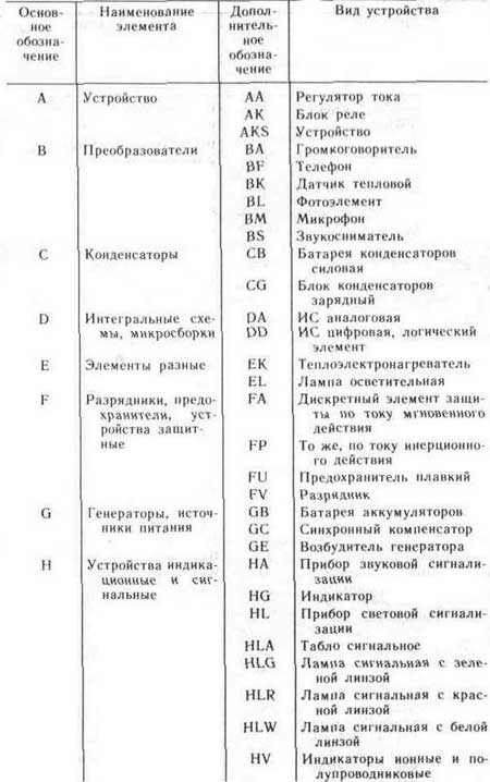
A Device (general designation)
AA Current Regulator
AK relay box
B Converters of non-electrical quantities to electrical (eg generators and power supplies) or vice versa, analog or multi-digit converters and sensors for indicating and measuring
BA Loudspeaker
BB Magnetostrictive element
BD Ionizing radiation detector
BE Selsin Receiver
BF Telephone (capsule)
BC Selsyn Sensor
BK Thermal sensor
BL Photocell
BM Microphone
BP Pressure sensor
BQ Piezoelectric
BR Speed sensor (tachogenerator)
BS Pickup
BV Speed sensor
C Capacitors
CB Power capacitor bank
CG Capacitor bank
D Integrated circuits, microassemblies
DA Analog integrated circuit
DD Digital integrated circuit
DS Storage Devices
DT Delay device
E Items are different
EK Heating element
EL Lighting lamp
ET Igniter
F Arresters, fuses, protective devices
FA Discrete instantaneous current protection element
FP Discrete inertial current protection element
FU Fuse fuse
FV Discrete voltage protection element, arrester
G Generators, power supplies
GB Battery
GC Synchronous compensator
GE Exciter Generator
H Indicating and signaling devices
HA Appliance sound signal izatsii
HG Character indicator
HL Light signaling indicator
HLA Signal board
HLG Signal lamp green
HLR Signal lamp red
HLW White signal lamp
HV Ionic and semiconductor indicators
K Relays, contactors, starters
KA Current relay
KCC Close command relay
KCT Trip command relay
KH Indicator relay
KK Electric thermal relay
KL Relay, intermediate
KM Contactor, magnetic starter
KT Time relay
KV Voltage relay
L Inductors, chokes
LL Choke for electroluminescent lighting
LM Motor field winding
M Engines
MA Electric motors
P Instruments, measuring equipment
PA Ammeter
PC Pulse counter
PE Not allowed
PF Frequency Counter
PI Active energy meter
PK Reactive energy meter
PR Ohmmeter
PS Recorder
PT Clock, action time meter
PV Voltmeter
PW Wattmeter
Q Switches and disconnectors in power circuits
QF Automatic circuit breaker
QK Short-circuiter
QS Disconnector
R Resistors
RK Thermistor
RP Potentiometer
RR Rheostat
RS Measuring shunt
RU Varistor
S Switching devices in control, signaling and measuring circuits
SA Switch or switch
SB Push button switch
SF Push-button switch (for devices without power circuit contacts)
SL Level tripped switch
SP - from pressure
SQ - from position (track)
SR - from the speed
SK - from temperature
T Transformers, autotransformers
TA Current transformer
TS Electromagnetic stabilizer
TV Voltage transformer
U Communication devices, converters of electrical quantities into electrical
UB Modulator
UF Frequency converter
UG Power supply
UI Discriminator
UR Demodulator
UZ Frequency converter, inverter, frequency generator, rectifier
V Electrovacuum and semiconductor devices
VD Diode, Zener diode
VL Electrovacuum device
VT Transistor
VS Thyristor
W Microwave lines and elements, antennas
WA Antenna
WE Coupler
WK Short-circuiter
WS Valve
WT Transformer, discontinuity, phase shifter
WU Attenuator
X Pin connections
XA Collector trolley, sliding contact
XP Pin
XS Socket
XT Dismountable connection
XW High frequency connector
Y Mechanical devices with electromagnetic drive
YA Electromagnet
YAB Electromagnetic lock
YB Electromagnetic brake
YC Electromagnetic Clutch
YH Electromagnet chuck or plate
Z Terminals, limiters, filters
ZL Limiter
ZQ Quartz filter
Foreign designations (Reference designators)
Unlike domestic ones, foreign designations have many letter designations of types differ.
Here is a list of common foreign designations.
AE Antenna
AT Attenuator
BR Bridge Rectifier
B, BT Battery
C Capacitor
CN Capacitor assembly
CRT Picture tube
D, CR Diode (Including Zener diodes, thyristors and LEDs)
DL Delay Line
DS Display
DSP Digital Signal Processor
F Fuse
FB or FEB Ferrite bead (for RFI filtering)
FD Fiducial
FET Field Effect Transistor
GDT Gas Discharge Lamp
IC Chip (also U)
J Socket
J, JP Jumper (jumper)
JFET Single Junction Field Effect Transistor
K Relay
L Inductance
LCD LCD
LDR Photoresistor
LED LED
LS Loudspeaker, sound emitters (tweeters)
M Electric motor
MCB Breaker
MK, Mic Microphone
MOSFET MOSFET
MP Mechanical parts (fasteners, etc.)
Ne Neon lamp
OP Operational Amplifier
P Plug
PCB Printed circuit board
PS Power supply
PU Pickup
Q Transistor (all kinds, also Tr)
R Resistor
RLA, RY Relay (also K)
RN Resistor network
RT Thermistor (also TH)
RV Varistor
S Switching devices
SCR Thyristor
SW Switch
T Transformer
TC Thermocouple
TUN Tuner
TFT TFT display
TH Thermistor (also RT)
TP Test point
Tr Transistor (all kinds, also Q)
U Microcircuit (also IC)
V Radio tube
VC Variable capacitor
VFD Gas Discharge Display
VLSI very large scale integration
VR Variable resistor
X Converters not elsewhere classified
X Quartz, ceramic resonator (also Y)
XMER Transformer
XTAL Crystal Resonator
Y Quartz, ceramic resonator (also X)
Z, ZD Zener diode
Historical
Before the introduction of GOST in the USSR, notation using the Cyrillic alphabet was also used (with the exception of R, C, L).
A antenna
B galvanic cell, accumulator, battery
Vk switch
Generator
Gr loudspeaker
D semiconductor diode
Dr throttle
Sound pickup
L radio tube
M microphone
Nl neon lamp
Switch
R relay
T transistor
Tl head phone
Tr transformer
TC thermistor
PV photocell
R resistor
C capacitor
L inductance
- electronic components assembled into analog and digital devices: televisions, measuring instruments, smartphones, computers, laptops, tablets. If earlier the details were depicted close to their natural appearance, today the conventional graphic designations of radio components on the diagram, developed and approved by the International Electrotechnical Commission, are used.
Types of electronic circuits
In electronics, several types of circuits are distinguished: schematic, wiring, block diagrams, voltage and resistance maps.Schematic diagrams
Such a wiring diagram gives a complete picture of all the functional nodes of the circuit, the types of connections between them, the principle of operation of electrical equipment. Schematic diagrams are commonly used in distribution networks... They are divided into two types:- Single line. In such a drawing, only power circuits are depicted.
- Full. If the electrical installation is simple, then all its elements can be displayed on one sheet. To describe the equipment, which includes how many circuits (power, measuring, control), drawings are made for each node and placed on different sheets.
Block diagrams
An independent part of an electronic device is called a block in electronics. A block is a general concept; it can include both a small and a significant number of parts. The block diagram (or block diagram) gives only a general idea of the structure of an electronic device. It does not display: the exact composition of the blocks, the number of ranges of their functioning, the schemes by which they are assembled. On the block diagram, blocks are indicated by squares or circles, and the connections between them are indicated by one or two lines. Signal directions are indicated by arrows. Block names in full or abbreviated form can be applied directly to the diagram. The second option is block numbering and decoding of these numbers in the table located in the margins of the drawing. On the graphic images of the blocks, the main details can be displayed or graphs of their work can be applied.Mounting
Wiring diagrams are convenient for self-drawing up an electrical circuit. They indicate the location of each element of the circuit, communication methods, laying of connecting wires. The designation of radioelements in such diagrams usually approaches their natural appearance.Voltage and resistance maps
A stress map (diagram) is a drawing, in which, next to individual parts and their terminals, the values of stresses characteristic of normal work device. The voltages are set in the gaps of the arrows showing where the measurements are to be made. On the resistance map, resistance values are indicated that are characteristic of a working device and circuits.How are the various radio components indicated on the diagrams
As it was said earlier, there is a certain graphic symbol to designate radio components of each type.Resistors
These parts are designed to regulate the current in the circuit. Fixed resistors have a certain and constant resistance value. For variables, the resistance is in the range from zero to the specified maximum value. The names and symbols of these radio components on the diagram are regulated by GOST 2.728-74 ESKD. In the general case, in the drawing, they represent a rectangle with two leads. American manufacturers designate resistors in the circuits with a zigzag line. the image of resistors on the diagrams the image of resistors on schematic diagrams
 Fixed resistors
They are characterized by resistance and power. They are indicated by a rectangle with lines indicating a specific power value. Exceeding the specified value will lead to the failure of the part. The diagram also indicates: the letter R (resistor), a number indicating the serial number of the part in the circuit, the value of resistance. These radio parts are designated by numbers and letters - "K" and "M". The letter "K" means kOhm, "M" - mOhm.Variable resistors
 the image of variable resistors on the diagrams Their design includes a movable contact, which changes the resistance value. The part is used as a regulating element in audio and other similar techniques. On the diagram, it is indicated by a rectangle indicating fixed and movable contacts. The drawing shows a constant nominal resistance. There are several options for connecting resistors:
  resistor connection options
 - Consistent. The end pin of one part is connected to the start pin of the other. A common current flows through all elements of the circuit. Connecting each subsequent resistor increases the resistance.
- Parallel. The initial conclusions of all resistances are connected at one point, the final ones - at another. Current flows through each resistor. The total resistance in such a circuit is always less than the resistance of an individual resistor.
- Mixed. This is the most popular type of connection of parts, combining the two described above.
Capacitors
 graphic representation of capacitors on the diagrams A capacitor is a radio component consisting of two plates separated by a dielectric layer. It is applied to the circuit in the form of two lines (or rectangles - for electrolytic capacitors), denoting the plates. The gap between them is a dielectric layer. Capacitors are second only to resistors in terms of popularity in circuits. Capable of accumulating electric charge with the subsequent return.
 - Fixed capacitors. The letter "C" is placed near the icon, the serial number of the part, the value of the nominal capacity.
- With variable capacity. The values of the minimum and maximum capacity are stamped next to the graphic icon.
Diodes and Zener Diodes
 graphic representation of diodes and zener diodes on circuits A diode is a semiconductor device designed to pass an electric current in one direction and create obstacles to its flow in the opposite direction. This radioelement is designated in the form of a triangle (anode), the top of which is directed towards the current flow. A line (cathode) is placed in front of the apex of the triangle. Zener diode is a kind of semiconductor diode. Stabilizes reverse polarity voltage applied to the terminals. A stabilizer is a diode, to the terminals of which a voltage of direct polarity is applied.
 Transistors
Transistors are semiconductor devices used to generate, amplify, and convert electrical oscillations. With their help, they control and regulate the voltage in the circuit. They differ in a variety of designs, frequency ranges, shapes and sizes. The most popular are bipolar transistors, denoted by the letters VT in the diagrams. They are characterized by the same electrical conductivity of the collector and emitter. graphic representation of transistors on the diagrams
 Microcircuits
Microcircuits are electronic components that are complex in composition. They are a semiconductor substrate in which resistors, capacitors, diodes and other radio components are integrated. They are used to convert electrical impulses into digital, analog, analog-digital signals. Manufactured with or without housing. The rules for the conventional graphic designation (UGO) of digital and microprocessor microcircuits are regulated by GOST 2.743-91 ESKD. According to them, the UGO has the shape of a rectangle. The diagram shows the supply lines to it. The rectangle consists only of the main field or the main field and two additional ones. In the main field, it is mandatory to indicate the functions performed by the element. The additional fields usually decipher the pin assignments. The main and additional fields may or may not be separated by a solid line. graphic representation of microcircuits
 Buttons, relays, switches
 graphic representation of buttons and switches on the diagram
 the image of the relay on the diagrams
 Letter designation of radio components in the diagram
Letter codes of radioelements on schematic diagrams
| Devices and elements | Letter code |
| Devices: amplifiers, telecontrol devices, lasers, masers; general designation | A |
| Converters of non-electrical quantities to electrical (except for generators and power supplies) or vice versa, analog or multi-digit converters, sensors for indicating or measuring; general designation | V |
| Speaker | VA |
| Magnetostrictive element | BB |
| Ionizing radiation detector | BD |
| Selsin sensor | Sun |
| Selsin-receiver | BE |
| Telephone (capsule) | Bf |
| Thermal sensor | VC |
| Photocell | BL |
| Microphone | VM |
| Pressure sensor | BP |
| Piezoelectric element | IN |
| RPM sensor, tachogenerator | BR |
| Pickup | BS |
| Speed sensor | BѴ |
| Capacitors | WITH |
| Integrated microcircuits, microassemblies: general designation | D |
| Integrated analog microcircuit | DA |
| Integrated digital microcircuit, logic element | DD |
| Information storage device (memory) | DS |
| Delay device | DT |
| Elements are different: general designation | E |
| Lighting lamp | EL |
| A heating element | EC |
| Arresters, fuses, protection devices: general designation | F |
| Fuse fuse | FU |
| Generators, power supplies, quartz generators: general designation | G |
| Battery of galvanic cells, accumulators | GB |
| Indicating and signaling devices; general designation | H |
| Sound alarm device | ON |
| Character indicator | HG |
| Light signaling device | HL |
| Relays, contactors, starters; general designation | TO |
| Electric thermal relayѳ | kk |
| Time relay | CT scan |
| Contactor, magnetic starter | km |
| Inductors, chokes; general designation | L |
| Motors, general designation | M |
| Measuring devices; general designation | R |
| Ammeter (milliammeter, microammeter) | RA |
| Pulse counter | PC |
| Frequency counter | PF |
| Ohmmeter | PR |
| Recording device | PS |
| Action time meter, clock | RT |
| Voltmeter | PV |
| Wattmeter | PW |
| Constant and variable resistors; general designation | R |
| Thermistor | RK |
| Measuring shunt | Rs |
| Varistor | RU |
| Switches, disconnectors, short-circuits in power circuits (in equipment power circuits); general designation | Q |
| Switching devices in control, signaling and measuring circuits; general designation | S |
| Switch or switch | SA |
| Push-button switch | SB |
| Automatic switch | SF |
| Transformers, autotransformers; general designation | T |
| Electromagnetic stabilizer | TS |
| Converters of electrical quantities into electrical, communication devices; general designation | and |
| Modulator | iv |
| Demodulator | UR |
| Discriminator | Ul |
| Frequency converter, inverter, frequency generator, rectifier | UZ |
| Semiconductor and vacuum devices; general designation | V |
| Diode, Zener diode | VD |
| Transistor | VT |
| Thyristor | VS |
| Electrovacuum device | VL |
| Microwave lines and elements; general designation | W |
| Coupler | WE |
| Koro tkoea we cat tel | Wk |
| Valve | WS |
| Transformer, phase shifter, discontinuity | WT |
| Attenuator | WU |
| Antenna | WA |
| Contact connections; general designation | X |
| Pin (plug) | XP |
| Socket (socket) | XS |
| Collapsible connection | XT |
| High frequency connector | XW |
| Mechanical devices with an electromagnetic drive; general designation | Y |
| Electromagnet | YA |
| Electromagnetic brake | YB |
| Electromagnetic clutch | YC |
| Terminal devices, filters; general designation | Z |
| Limiter | ZL |
| Quartz filter | ZQ |
Letter codes for the functional purpose of a radio-electronic device or element
| Functional purpose of the device, element | Letter code |
| Auxiliary | A |
| Counting | WITH |
| Differentiating | D |
| Protective | F |
| Test | G |
| Signal | H |
| Integrating | 1 |
| Hpavny | M |
| Measuring | N |
| Proportional | R |
| State (start, stop, limit) | Q |
| Return, reset | R |
| Memorizing, recording | S |
| Synchronizing, delaying | T |
| Speed (acceleration, deceleration) | V |
| Summing | W |
| Multiplication | X |
| Analog | Y |
| Digital | Z |
Letter abbreviations for electronics
| Letter abbreviation | Explanation of abbreviation |
| AM | amplitude modulation |
| AFC | automatic frequency control |
| APCHG | automatic local oscillator frequency adjustment |
| APCHF | automatic frequency and phase adjustment |
| AGC | automatic gain control |
| ARYA | automatic brightness control |
| AS | acoustic system |
| AFU | antenna feeder |
| ADC | analog-to-digital converter |
| Frequency response | frequency response |
| BGIMS | large hybrid integrated circuit |
| NOS | wireless remote control |
| BIS | large integrated circuit |
| Biofeedback | signal processing unit |
| BP | power unit |
| BR | scanner |
| DBK | radio channel unit |
| BS | information block |
| BTK | blocking transformer personnel |
| BTS | blocking transformer lowercase |
| BOO | Control block |
| BC | color block |
| BCI | integrated chromaticity unit (using microcircuits) |
| VD | video detector |
| VIM | pulse time modulation |
| WU | video amplifier; input (output) device |
| HF | high frequency |
| G | heterodyne |
| GW | reproducing head |
| MHF | high frequency generator |
| MHF | hyperhigh frequency |
| GZ | start generator; recording head |
| GIR | heterodyne resonance indicator |
| GIS | hybrid integrated circuit |
| GKR | frame generator |
| GKCH | sweeping frequency generator |
| GMV | meter wave generator |
| GPA | smooth range generator |
| GO | envelope generator |
| HS | signal generator |
| GSR | line scan generator |
| gss | standard signal generator |
| yy | clock generator |
| GU | universal head |
| GUN | voltage controlled generator |
| D | detector |
| dv | long waves |
| dd | fractional detector |
| day | voltage divider |
| dm | power divider |
| dmv | decimeter waves |
| DU | remote control |
| DShPF | dynamic noise reduction filter |
| EASC | unified automated communication network |
| ESKD | unified system of design documentation |
| hr | sound frequency generator; master oscillator |
| ss | decelerating system; sound signal; pickup |
| ZCH | sound frequency |
| AND | integrator |
| iqm | pulse code modulation |
| IKU | quasi-peak level meter |
| ims | integrated circuit |
| ini | linear distortion meter |
| inch | infra-low frequency |
| and he | reference voltage source |
| sp | power supply |
| ichh | frequency response meter |
| To | switch |
| KBV | traveling wave ratio |
| Kv | short waves |
| kvh | extremely high frequency |
| kzv | recording-playback channel |
| Kim | pulse code modulation |
| kk | frame reel deflector |
| km | coding matrix |
| csch | extremely low frequency |
| efficiency | efficiency |
| KS | coil deflection line |
| csv | standing wave ratio |
| ksvn | voltage standing wave ratio |
| CT scan | check Point |
| CF | focusing coil |
| TWT | traveling wave lamp |
| lz | delay line |
| fishing | backward wave lamp |
| lpd | avalanche diode |
| lppt | tube semiconductor TV |
| m | modulator |
| MA | magnetic antenna |
| MB | meter waves |
| mdp | metal-dielectric-semiconductor structure |
| MNP | metal-oxide-semiconductor structure |
| ms | chip |
| MU | microphone amplifier |
| nor | nonlinear distortion |
| LF | low frequency |
| ABOUT | common base (switching on the transistor according to the scheme with a common base) |
| sheepskin | very high frequency |
| oi | common source (turning on the transistor * according to the scheme with a common source) |
| OK | common collector (switching on the transistor according to the scheme with a common collector) |
| onch | very low frequency |
| oos | negative feedback |
| OS | deflection system |
| OU | operational amplifier |
| OE | common emitter (switching on the transistor according to the scheme with a common emitter) |
| Surfactant | surface acoustic waves |
| pds | dual-voice prefix |
| Remote control | remote control |
| pkn | code-voltage converter |
| pnc | voltage-to-code converter |
| pnch | converter voltage frequency |
| pos | positive feedback |
| PPU | jamming device |
| pch | intermediate frequency; frequency converter |
| ptk | tv channel switch |
| pts | full tv signal |
| Vocational school | industrial television set |
| PU | preliminary effort |
| PUV | playback preamplifier |
| BLS | recording preamplifier |
| PF | band pass filter; piezofilter |
| nx | transfer characteristic |
| pcts | full color television signal |
| Radar | line linearity regulator; radar station |
| RP | memory register |
| RPCHG | manual adjustment of the local oscillator frequency |
| RRS | row size adjuster |
| PC | shift register; mixing regulator |
| RF | notch or block filter |
| CEA | electronic equipment |
| SBDU | wireless remote control system |
| VLSI | ultra-large-scale integrated circuit |
| SV | medium waves |
| swp | touch program selection |
| Microwave | ultra high frequency |
| cr | signal generator |
| SDV | extra-long waves |
| SDU | dynamic light installation; remote control system |
| SC | channel selector |
| SLE | all-wave channel selector |
| sk-d | decimeter wave channel selector |
| SK-M | meter wave channel selector |
| CM | mixer |
| ench | ultra-low frequency |
| Joint venture | mesh field signal |
| ss | sync signal |
| ssi | horizontal sync pulse |
| SU | selector amplifier |
| mid | average frequency |
| Tv | tropospheric radio waves; TV |
| tvs | output transformer line |
| tvz | audio output channel transformer |
| tvk | output transformer |
| Titus | TV test chart |
| TKE | temperature coefficient of capacitance |
| weaves | temperature coefficient of inductance |
| tkmmp | temperature coefficient of initial permeability |
| tcns | temperature coefficient of stabilization voltage |
| tks | temperature coefficient of resistance |
| mf | network transformer |
| mall | television center |
| ttsp | color stripe table |
| THAT | technical conditions |
| Have | amplifier |
| HC | playback amplifier |
| UVS | video amplifier |
| UVH | fetch-store |
| UHF | high frequency signal amplifier |
| UHF | UHF |
| UZ | recording amplifier |
| UZCH | audio amplifier |
| VHF | ultrashort waves |
| ULPT | unified semiconductor tube TV |
| ULCT | unified tube semiconductor color TV |
| ULT | unified tube TV |
| UMZCH | audio power amplifier |
| CNT | unified tv |
| ULF | low frequency amplifier |
| UNU | voltage controlled amplifier. |
| UTP | constant current amplifier; unified semiconductor TV |
| UCH | intermediate frequency amplifier |
| UPCHZ | intermediate frequency amplifier sound? |
| UPCHI | image intermediate frequency amplifier |
| URCH | radio frequency amplifier |
| US | interface device; comparison device |
| UHCH | microwave amplifier |
| OSS | horizontal sync amplifier |
| USU | universal touch device |
| Uu | control device (node) |
| UE | accelerating (control) electrode |
| UEIT | universal electronic test chart |
| PLL | phase locked loop |
| HPF | high pass filter |
| FD | phase detector; photodiode |
| FIM | phase-pulse modulation |
| FM | phase modulation |
| LPF | low pass filter |
| FPF | intermediate frequency filter |
| FPChZ | audio intermediate frequency filter |
| FPCI | image IF filter |
| FSI | lumped selectivity filter |
| FSS | concentrated selection filter |
| FT | phototransistor |
| PFC | phase-frequency response |
| DAC | digital-to-analog converter |
| Digital computer | digital computer |
| CMU | color music installation |
| CT | central television |
| BH | frequency detector |
| CHIM | pulse frequency modulation |
| chm | frequency modulation |
| shim | pulse width modulation |
| shs | noise signal |
| ev | electron volt (e V) |
| COMPUTER. | electronic computer |
| emf | electromotive force |
| eq | electronic switch |
| CRT | cathode-ray tube |
| AMY | electronic musical instrument |
| emos | electromechanical feedback |
| EMF | electromechanical filter |
| EPU | playing device |
| Electronic computer | electronic digital computer |
Almost all UOS, all electronic and electrical products manufactured by industrial organizations and enterprises, home craftsmen, young technicians and radio amateurs, contain a certain amount of various purchased ERI and elements produced mainly by domestic industry. But for recent times there is a tendency to use ERE and foreign-made components. These include, first of all, PPP, capacitors, resistors, transformers, chokes, electrical connectors, batteries, HIT, switches, installation products and some other types of ERE.
Used purchased components or independently manufactured EREs will necessarily be reflected in the basic and installation electrical diagrams devices, in drawings and other TD, which are carried out in accordance with the requirements of ESKD standards.
Particular attention is paid to circuit diagrams, which determine not only the main electrical parameters, but also all the elements included in the device and the electrical connections between them. To understand and read the circuit diagrams, you must carefully familiarize yourself with the elements and accessories included in them, know exactly the scope and principle of operation of the device in question. As a rule, information about the ERE used is indicated in reference books and specifications - a list of these elements.
The connection of the list of ERE components with their conventional graphic designations is carried out through reference designations.
To construct conventional graphic symbols for ERE, standardized geometric symbols are used, each of which is used separately or in combination with others. In this case, the meaning of each geometric image in the conventional designation in many cases depends on the combination with which other geometric symbol it is used.
The standardized and most commonly used conventional graphic designations of ERE in electrical circuit diagrams are shown in Fig. 1. 1. These designations relate to all component elements of the circuits, including ERE, conductors and connections between them. And here the condition for the correct designation of the same type of ERE components and products is of paramount importance. For this purpose, reference designations are used, a mandatory part of which is the letter designation of the type of element, the type of its design and the digital designation of the ERE number. The diagrams also use the additional part of the designation of the ERE position, indicating the function of the element, in the form of a letter. The main types of letter designations of circuit elements are given in table. 1.1.
The designations in the drawings and diagrams of elements of general use refer to qualification ones that establish the type of current and voltage. type of connection, control methods, pulse shape, type of modulation, electrical connections, direction of transmission of current, signal, energy flow, etc.
Currently, the population and the trade network are in operation a significant number of various electronic devices and devices, radio and television equipment, which are manufactured by foreign firms and various joint-stock companies. In stores you can buy Various types ERI and ERE with foreign designations. Table 1. 2 provides information about the most common ERE of foreign countries with the appropriate designations and their analogues of domestic production.
This information is published for the first time in such a volume.
1- pnp structure transistor in a package, general designation;
2- transistor structures n-p-n in the case, general designation,
3 - field-effect transistor with p-n junction and n channel,
4 - field-effect transistor with p-n junction and p channel,
5 - unijunction transistor with base n type, b1, b2 - base terminals, e - emitter output,
6 - photodiode,
7 - rectifier diode,
8 - one-way zener diode (avalanche rectifier diode),
9 - heat-electric diode,
10 - diode dinistor, lockable in the opposite direction;
11 - zener diode (diode avalanche rectifier) with double-sided conductivity,
12 - triode thyristor;
13 - photoresistor;
14 - variable resistor, rheostat, general designation,
15 - variable resistor,
16 - variable resistor with taps,
17 - trimmer resistor-potentiometer;
18 - thermistor with a positive temperature coefficient of direct heating (heating),
19 - varistor;
20 - constant capacitor, general designation;
21 - polarized fixed capacitor;
22 - polarized electrolytic oxide capacitor, general designation;
23 - constant resistor, general designation;
24 - constant resistor with a rated power of 0.05 W;
25 - constant resistor with a rated power of 0, 125 W,
26 - constant resistor with a rated power of 0.25 W,
27 - constant resistor with a rated power of 0.5 W,
28 - constant resistor with a rated power of 1 W,
29 - constant resistor with a rated power dissipation of 2 W,
30 - constant resistor with a rated power dissipation of 5 W;
31 - constant resistor with one symmetrical additional tap;
32 - constant resistor with one asymmetrical additional tap;
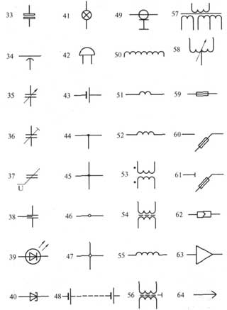
Fig 1.1 Symbols of ERE in electrical, radio engineering and automation circuits
33 - non-polarized oxide capacitor;
34 - pass-through capacitor (arc denotes a housing, an external electrode);
35 - variable capacitor (arrow indicates the rotor);
36 - trimmer capacitor, general designation;
37 - varicond;
38 - noise suppression capacitor;
39 - LED;
40 - tunnel diode;
41 - lighting and signal incandescent lamp;
42 - electric bell;
43 - galvanic or battery cell;
44 - electrical communication line with one branch;
45 - electrical communication line with two branches;
46 - a group of wires connected to one point of electrical connection. Two wires;
47 - four wires connected to one electrical connection point;
48 - a battery of galvanic cells or a rechargeable battery;
49 - coaxial cable. The screen is connected to the body;
50 - winding of a transformer, autotransformer, choke, magnetic amplifier;
51 - working winding of the magnetic amplifier;
52 - control winding of the magnetic amplifier;
53 - transformer without a core (magnetic circuit) with permanent coupling (dots indicate the beginning of the windings);
54 - transformer with a magnetodielectric core;
55 - inductor, choke without magnetic circuit;
56 - single-phase transformer with a ferromagnetic magnetic core and a screen between the windings;
57 - single-phase three-winding transformer with a ferromagnetic magnetic circuit with a tap in the secondary winding;
58 - single-phase autotransformer with voltage regulation;
59 - fuse;
60 - fuse switch;
61 - fuse disconnector;
62 - detachable pin connection;
63 - amplifier (the direction of signal transmission indicates the apex of the triangle at horizontal line communication);
64 - pin of detachable contact connection;

Fig 1.1 Symbols of ERE in electrical radio engineering and automation circuits
65 - socket of a detachable contact connection,
66 - contact of a dismountable connection, for example, using a clip
67 - contact of a non-separable connection, for example, carried out by soldering
68 - push-button single-pole push-button switch with self-resetting closing contact
69 - contact of the switching device opening, general designation
70 - closing contact of a switching device (switch, relay), general designation. The switch is single-pole.
71 - changeover contact of the switching device, general designation. Single pole double throw switch.
72- three-position changeover contact with neutral position
73 - closing contact without self-return
74 - push-button switch with break contact
75 - push-button exhaust switch with NO contact
76 - push-button switch with button return,
77 - push-button exhaust switch with break contact
78 - push-button switch with return by pressing the button a second time,
79 - electrical relay with normally open and changeover contacts,
80 - relay polarized in one direction of current in a winding with a neutral position
81 - relay polarized in both directions of current in the winding with a neutral position
82 - electric thermal relay without self-return, with a return by pressing the button a second time,
83 - detachable single-pole connection
84 - socket of a five-wire pin detachable connection
85 - pin of the pin detachable coaxial connection
86 - socket of contact connection
87 - pin four-wire connection
88 - socket of a four-wire connection
89 - jumper switching opening circuit
Table 1.1. Letter designations of circuit elements
Continuation of table 1.1


In order to correctly read and understand what this or that diagram or drawing related to electricity means, you need to know how the icons and symbols depicted on them are deciphered. A large amount of information contains the letter designations of elements in electrical circuits, determined by various regulatory documents. All of them are displayed in Latin characters in the form of one or two letters.
One-letter symbolism of elements
Letter codes corresponding to individual types of elements most widely used in electrical circuits are combined into groups designated by one symbol. Letter designations correspond to GOST 2.710-81. For example, the letter "A" refers to the "Devices" group, which consists of lasers, amplifiers, telecontrol devices and others.
In the same way, the group denoted by the symbol "B" is deciphered. It consists of devices that convert non-electrical quantities into electrical quantities, which do not include generators and power supplies. This group is complemented by analog or multi-digit converters as well as indicating or measuring sensors. The components themselves included in the group are represented by microphones, loudspeakers, pickups, detectors of ionizing radiation, thermoelectric sensing elements, etc.
All letter designations corresponding to the most common elements are combined in a special table for ease of use:
|
The first alphabetic character required to be reflected in the marking |
Group of basic types of elements and devices |
Elements that make up the group (the most typical examples) |
|
|
Devices |
Lasers, masers, telecontrol devices, amplifiers. |
||
|
Apparatus for converting non-electrical quantities into electrical (without generators and power supplies), analog and multi-charge converters, sensors for indications or measurements |
Microphones, loudspeakers, pickups, ionizing radiation detectors, sensitive thermoelectric elements. |
||
|
Capacitors |
|||
|
Micro assemblies, integrated circuits |
Digital and analog integrated circuits, memory and delay devices, logic elements. |
||
|
Miscellaneous elements |
Various types of lighting devices and heating elements. |
||
|
Fuse designation in the diagram, arresters, protective devices |
Fuses, arresters, discrete current and voltage protection elements. |
||
|
Power supplies, generators, quartz oscillators |
Rechargeable batteries, power supplies on an electrochemical and electrothermal basis. |
||
|
Devices for signals and indications |
Indicators, light and sound signaling devices |
||
|
Contactors, relays, starters |
Voltage and current relays, time relays, electric thermal relays, magnetic starters, contactors. |
||
|
Chokes, inductors |
Chokes in fluorescent lighting. |
||
|
Engines |
DC and AC motors. |
||
|
Measuring instruments and equipment |
Counters, clocks, showing, registering and measuring instruments. |
||
|
Power circuit breakers, short-circuits, disconnectors. |
|||
|
Resistors |
|||
|
Pulse counters |
|||
|
Frequency meters |
|||
|
Active energy meters |
|||
|
Reactive energy meters |
|||
|
Recording devices |
|||
|
Action time meters, hours |
|||
|
Voltmeters |
|||
|
Wattmeters |
|||
|
Switches and disconnectors in power circuits |
Circuit breakers |
||
|
Short-circuits |
|||
|
Disconnectors |
|||
|
Resistors |
Thermistors |
||
|
Potentiometers |
|||
|
Measuring shunts |
|||
|
Varistors |
|||
|
Switching devices in measurement, control and signaling circuits |
Switches and switches |
||
|
Push-button switches |
|||
|
Automatic switches |
|||
|
Switches triggered by various factors: From level |
|||
|
From pressure |
|||
|
From position (travel) |
|||
|
From the speed |
|||
|
From temperature |
|||
|
Transformers, autotransformers |
Current transformers |
||
|
Electromagnetic stabilizers |
|||
|
Voltage transformers |
|||
|
Communication devices, converters of non-electrical quantities into electrical |
Modulators |
||
|
Demodulators |
|||
|
Discriminators |
|||
|
Frequency generators, inverters, frequency converters |
|||
|
Semiconductor and vacuum devices |
Diodes, Zener diodes |
||
|
Electrovacuum devices |
|||
|
Transistors |
|||
|
Thyristors |
|||
|
Antennas, microwave lines and elements |
Taps |
||
|
Short-circuits |
|||
|
Transformers, phase shifters |
|||
|
Attenuators |
|||
|
Contact connections |
Sliding contacts, current collectors |
||
|
Dismountable connections |
|||
|
High frequency connectors |
|||
|
Mechanical devices with electromagnetic drive |
Electromagnets |
||
|
Electromagnetic brakes |
|||
|
Electromagnetic clutches |
|||
|
Electromagnetic holders or plates |
|||
|
Limiters, terminal devices, filters |
Limiters |
||
|
Quartz filters |
In addition, GOST 2.710-81 defines Special symbols to designate each item.
Conditional graphic symbols of electronic components in circuits
How to learn to read schematic diagrams
Those who have just started studying electronics are faced with the question: "How to read schematic diagrams?" The ability to read circuit diagrams is necessary for self-assembly of an electronic device and not only. What is the schematic diagram? A schematic diagram is a graphical representation of a collection of electronic components connected by live conductors. The development of any electronic device begins with the development of its schematic diagram.
It is on schematic diagram it is shown how exactly the radio components need to be connected in order to end up with a finished electronic device that is capable of performing certain functions. To understand what is shown on the schematic diagram, you need, firstly, to know the symbolic designation of those elements that make up electronic circuit... Any radio component has its own conventional graphic designation - UGO ... As a rule, it displays a structural device or purpose. So, for example, the conventional graphic designation of the speaker very accurately conveys the real device of the speaker. This is how the speaker is indicated in the diagram.

Agree, very similar. This is what the symbol for the resistor looks like.

An ordinary rectangle, inside which its power can be indicated (In this case, a 2 W resistor, as evidenced by two vertical lines). But this is how an ordinary capacitor of constant capacity is designated.

These are fairly simple elements. But semiconductor electronic components, such as transistors, microcircuits, triacs, have a much more sophisticated image. So, for example, any bipolar transistor has at least three terminals: base, collector, emitter. In a conventional image of a bipolar transistor, these conclusions are shown in a special way. To distinguish a resistor from a transistor on the diagram, firstly, you need to know the conventional image of this element and, preferably, its basic properties and characteristics. Since each radio component is unique, certain information can be graphically encrypted in the conventional image. For example, it is known that bipolar transistors can have different structures: p-n-p or n-p-n... Therefore, UGO transistors of different structures are somewhat different. Take a look ...

Therefore, before starting to understand the circuit diagrams, it is advisable to get acquainted with the radio components and their properties. So it will be easier to figure out what is still shown in the diagram.
On our site, it has already been told about many radio components and their properties, as well as their symbol on the diagram. If you forgot - welcome to the "Start" section.
In addition to conventional images of radio components, other clarifying information is indicated on the schematic diagram. If you look closely at the diagram, you will notice that next to each conventional image of the radio component there are several Latin letters, for example, VT , BA , C etc. This is an abbreviated letter designation of a radio component. This is done so that when describing the operation or setting up the circuit, one can refer to one or another element. It is not difficult to notice that they are also numbered, for example, like this: VT1, C2, R33, etc.
It is clear that there can be as many radio components of the same type in the circuit. Therefore, in order to streamline all this, numbering is applied. The numbering of parts of the same type, for example resistors, is carried out on schematic diagrams according to the "AND" rule. This is, of course, just an analogy, but quite illustrative. Take a look at any diagram and you will see that radio parts of the same type are numbered starting from the left. top corner, then in order the numbering goes down, and then again the numbering starts at the top, and then down, and so on. Now remember how you write the letter "I". I think everything is clear with this.
What else to tell about the schematic diagram? Here's what. On the diagram, next to each radio component, its main parameters or standard type are indicated. Sometimes this information is placed in a table to make the concept easier to understand. For example, next to the image of a capacitor, as a rule, its nominal capacity in microfarads or picofarads is indicated. The rated operating voltage may also be indicated if relevant.
Next to the UGO of the transistor, the type of the transistor is usually indicated, for example, KT3107, KT315, TIP120, etc. In general, for any semiconductor electronic components such as microcircuits, diodes, zener diodes, transistors, the component type is indicated, which is supposed to be used in the circuit.
For resistors, only its nominal resistance in kilo-ohms, ohms or megohms is usually indicated. The power rating of the resistor is encrypted with oblique lines inside the rectangle. Also, the power of the resistor in the diagram and on its image may not be indicated. This means that the power of the resistor can be anything, even the smallest, since the operating currents in the circuit are insignificant and even the smallest resistor available in the industry can withstand them.
Here in front of you the simplest scheme two-stage audio frequency amplifier. The diagram shows several elements: a power battery (or just a battery) GB1 ; fixed resistors R1 , R2 , R3 , R4 ; power switch SA1 , electrolytic capacitors C1 , C2 ; fixed capacitor C3 ; high impedance speaker BA1 ; bipolar transistors VT1 , VT2 structures n-p-n... As you can see, I am referring to a specific element in the diagram using Latin letters.

What can we learn by looking at this diagram?
Any electronics operate on electric current, therefore, the current source from which the circuit is powered must be indicated on the diagram. The source of current can be both a battery and an AC mains or a power supply.
So. Since the amplifier circuit is powered by a GB1 DC battery, therefore, the battery has a polarity: plus "+" and minus "-". On the conventional image of the battery, we see that the polarity is indicated next to its terminals.
Polarity. It is worth mentioning separately. For example, electrolytic capacitors C1 and C2 have polarity. If we take a real electrolytic capacitor, then on its case it is indicated which of its conclusions is positive and which is negative. And now, the most important thing. When self-assembling electronic devices, it is necessary to observe the polarity of connecting the electronic parts in the circuit. Failure to do so simple rule will lead to inoperability of the device and, possibly, other undesirable consequences. Therefore, do not be lazy from time to time to glance at the schematic diagram, according to which you assemble the device.
The diagram shows that to assemble the amplifier, you will need constant resistors R1 - R4 with a power of at least 0.125 W. This can be seen from their designation.
You can also notice that the resistors R2 * and R4 * marked with an asterisk * ... This means that the nominal resistance of these resistors must be selected in order to establish optimal operation of the transistor. Usually, in such cases, instead of resistors, the value of which needs to be selected, a variable resistor with a resistance slightly greater than the value of the resistor indicated in the diagram is temporarily installed. To determine the optimal operation of the transistor in this case, a milliammeter is connected to the open circuit of the collector. The place on the diagram where you need to connect the ammeter is indicated on the diagram like this. The current is also indicated, which corresponds to the optimal operation of the transistor.

Recall that to measure the current, the ammeter is included in the open circuit.
Next, turn on the amplifier circuit with the SA1 switch and begin to change the resistance with a variable resistor R2 *... At the same time, the readings of the ammeter are monitored and the milliammeter shows a current of 0.4 - 0.6 milliamperes (mA). At this, the setting of the mode of the transistor VT1 is considered complete. Instead of the variable resistor R2 *, which we installed in the circuit at the time of adjustment, a resistor with such a nominal resistance is installed, which is equal to the resistance of the variable resistor obtained as a result of adjustment.
What is the conclusion from all this long narration about the establishment of the work of the circuit? And the conclusion is that if on the diagram you see any radio component with an asterisk (for example, R5 *), this means that in the process of assembling the device according to this schematic diagram, it will be necessary to establish the work of certain sections of the circuit. How to establish the operation of the device, as a rule, is mentioned in the description of the schematic diagram itself.
If you look at the amplifier circuit, you can also notice that there is such a symbol on it.
This designation shows the so-called common wire... In technical documentation, it is called a body. As you can see, the common wire in the shown amplifier circuit is the wire that is connected to the negative "-" terminal of the GB1 battery. For other circuits, the common wire can also be the wire that is connected to the plus of the power supply. In circuits with bipolar power, the common wire is indicated separately and is not connected to either the positive or negative terminal of the power supply.
Why is the "common wire" or "case" indicated on the diagram?
All measurements in the circuit are carried out with respect to the common wire, with the exception of those that are negotiated separately, and also peripheral devices are connected with respect to it. The common wire carries the total current consumed by all elements of the circuit.
The common wire of the circuit in reality is often connected to metal case an electronic device or a metal chassis on which the printed circuit boards are mounted.
It should be understood that the common wire is not the same as the "ground". " Earth"- this is grounding, that is, an artificial connection to the ground by means of a grounding device. It is indicated in the diagrams as follows.
In some cases, the common wire of the device is connected to ground.
As already mentioned, all radio components in the schematic diagram are connected using current-carrying conductors. The live conductor can be a copper wire or a copper foil track on printed circuit board... A live conductor in the schematic diagram is indicated by a regular line. Like this.
![]()
The places of soldering (electrical connection) of these conductors to each other, or to the terminals of radio components are shown with a bold point. Like this.
It should be understood that on a schematic diagram, a dot indicates only the connection of three or more conductors or terminals. If the diagram shows the connection of two conductors, for example, the output of a radio component and a conductor, then the diagram would be overloaded with unnecessary images and at the same time its informativeness and conciseness would be lost. Therefore, it should be understood that in real scheme there may be electrical connections that are not shown in the circuit diagram.
The next part deals with connections and connectors, repetitive and mechanically connected elements, shielded parts and conductors. Click " Further"...