Ultraviolet lamp DRL ">
Now chemistry based on photocatalysts is becoming widespread. Various adhesives, varnishes, photosensitive emulsions and other interesting achievements of the chemical industry. Unfortunately, industrial UV installations cost a lot of money.
What if you just want to try chemistry? will it fit or not? For this purpose, buying branded devices for N kilobucks is too curly ...
On the territory of the former USSR, they usually get out of the situation by extracting quartz tubes from DRL-type lamas, there is a whole line of llamas from DRL-125 to DRL-1000, with the help of them you can get sufficiently powerful radiation, this radiation is usually enough for most occasional tasks. Type to harden glue or varnish once a month, or light up a photorezist.

How to get a tube from DRL lamps, how to do it safely, a lot of information has been written. I would like to touch upon another aspect, namely the launch of these lamps with minimal financial costs.
Normally, a special inductor with increased magnetic scattering is used for starting. But even he is not always available. it is heavy, then usually delivery to the regions costs a pretty penny. Choke 700W + shipping costs $ 100. That for the option to try, too, is never cheap.

A bit of theory:
The main problem with starting mercury lamps is the presence of an arc discharge. Moreover, a cold lamp and a hot one have fundamentally different resistance to the burning arc. Approximately from units of Ohms to tens of Ohms. Accordingly, for this, a choke is used that limits the current during start-up and operation of the lamp. It must be admitted that the choke is a rather archaic tool, and for expensive and powerful llamas used in UF-dryers (several kilowatts of power, and several thousand dollars per lamp) electronic arc stabilization units are used. These blocks allow for more accurate arc tolerance, thereby extending lamp life and reducing curing problems. Even for an archaic DRL, the manufacturer writes that the voltage spread is no more than 3%, otherwise a decrease in the service life.
How to start a DRL Lamp without a throttle using improvised means?
The answer is simple, all you need to do is limit the current in all modes of operation, starting with warming up and ending with the operating mode. We will limit it with a resistor.
But since the resistor needs to be very powerful, we will use the heating devices at hand (incandescent lamps, irons, kettles, hot water heaters, hand-held boilers, etc.) It sounds ridiculous, but it will work and fulfill its tasks.
The only drawback is the excessive consumption of electricity, i.e. if we run a 400W DRL lamp on the ballast, about 250W will be released into heat. But I think for the task of trying ultraviolet light, or for episodic works, this is unimportant.
Why didn't anyone do that?
Why no one, there are DRB lamps in which this particular principle is used. Next to the quartz tube is the filament of an ordinary light bulb.
And the writers on the Internet apparently did not teach physics at school. Well, of course, one more small nuance, you need a heating circuit, i.e. we heat the lamp with one resistor, and we bring it to the operating mode with another. But I think many will cope with a switch and two wires :)
So the scheme:
So, for many, I tried to depict the correct schemes, this is a dark forest, in pictures. More close to life.

How it works?
1) Warm-up stage, the switch must be open !!! We turn on the lamp to the network. The incandescent lamp begins to glow brightly, the tube in the DRL lamp begins to flicker and slowly flare up. In 3-5 minutes the tube in the lamp will already start to shine brightly enough.
2) Second, we close the switch to the main ballast, the current will increase even more and after another 3 minutes the lamp will enter the operating mode.
Attention in total on the load of the lamp + irons, kettles, etc. will emit powers comparable to the wattage of the lamp. The iron, for example, may turn off the built-in thermostat, and the power of the DRL lamp will decrease.
For most, such a circuit will be very difficult, especially for those who do not have a resistance meter. For them I Simplified the scheme even more:

The start-up is simple, we unscrew the lamps, leave only the required amount (1-2 pieces) to start the burner, and as it warms up, we begin to screw it in. For powerful DRL lamps, tubular halogen lamps can be used as a resistor.
Now the tricky part:
Probably, many have already understood that lamps and loads need to be selected somehow? Of course, if you take some kind of iron and connect it to the DRL-125 lamp, nothing will remain from the lamp, and you will get mercury contamination. By the way, the same will happen if you take a choke from the DRL-700 for the DRL-125 lamp. Those. the brain still needs to be turned on!
A few simple rules to save strength, nerves and health :)
1) You cannot be guided by the nameplates of the devices, you need to measure the real resistance with an ohmmeter and make calculations. Or use it with a margin of safety, choosing a little less power than possible.
2) It is useless to measure the resistance of incandescent lamps, a cold coil has 10 times less resistance than a hot one. Incandescent lamps are the worst choice, you have to navigate by the inscription on the lamp. And in no case do not turn on the load from the incandescent lamps at once, screw them in one at a time, reducing the current surges. Since I suspect that this will be the most popular way to turn on the DRL lamp without a choke. I shot a video for an example.
3) For general reasons, to start heating the DRL lamp, use a load not much more than its rated power. For example, DRL-400 for warming up, use 300-400 watts.
Table for different lamps:
| Lamp type | V-arcs | I-arcs | R-arcs | Ballast resistor | The inscription on the ballast \ iron \ lamp \ ten | Heat at the ballast during work |
|---|---|---|---|---|---|---|
| DRL-125 | 125 in | 1 A | 125 Ohm | 80 ohm | 500 watts | 116 watts |
| DRL-250 | 130 in | 2 A | 68 Ohm | 48 ohm | 1000 watts | 170 watts |
| DRL-400 | 135 in | 3 A | 45 Ohm | 30 ohm | 1600 Wt | 250 watts |
| DRL-700 | 140 in | 5 A | 28 ohm | 17 ohm | 2850 Wt | 380 watts |
Comments to the table:
1 - the name of the lamp.
2 - operating voltage on a heated lamp.
3 is the nominal operating current of the lamp.
4 - the approximate working resistance of the lamp in a heated state.
5 - resistance of the ballast resistor for full power operation.
6 - the approximate power written on the nameplate of the device (heating elements, lamps, etc.) that will be used as a ballast resistor.
7 - power in watts, which will be allocated on the ballast resistor, or a device replacing it.
If it is difficult, or it seems to you that it will not work. I took off the video, as an example, a DRL-400 lamp I start it with three 300W lamps (they cost me 30 rubles each). The power on the DRL lamp turned out to be about 300W, the loss on incandescent lamps is 180W. As you can see, nothing is difficult.
Now fly in the ointment:
Unfortunately, it is not as easy to use burners from DRL lamps in commercial applications as it seems. The quartz tube in DRL lamps is made based on calculations of operation in an inert gas environment. In this regard, some technological simplifications have been introduced in production. This immediately affects the lifespan as soon as you break the external bulb. Although, of course, taking into account the low cost (Watt / ruble), it is not yet known that specialized lamps, or constantly changing emitters from DRLs, are more profitable. I will list the main mistakes in the design of any devices from DRL lamps:
1) Cooling the lamp. The lamp must be hot, only indirect cooling. Those. it is necessary to cool the reflector of the lamp and not the lamp itself. The ideal option is to put the emitter in a quartz tube, and cool the outer quartz tube, and not the emitter itself.
2) Using a lamp without reflectors, i.e. smashed the flask and screwed the lamp into the socket. The fact is that with this approach, the lamp does not warm up to operating temperatures, there is a strong degradation and a decrease in the service life by a factor of thousands. The lamp should be placed in at least a U-shaped reflector made of aluminum to raise the temperature around the lamp. And at the same time focus the radiation.
3) Combat ozone. Powerful hood fans are installed, and if the flow goes through the lamp, then we get cooling. It is necessary to develop an indirect ozone removal, so that the air / ozone intake goes as far as possible from the lamp.
4) Clumsy when trimming the base. When obtaining the emitter, you must act as carefully as possible, otherwise microcracks in the places where the conductors are connected to the lamp will depressurize it in a dozen hours of burning.
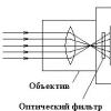
A very common question about emission spectrum of a quartz bulb from DRL lamps... Because some chemical manufacturers write the sensitivity spectrum of their photoinitiators.
So the UV emitter of the DRL lamp is located at the midpoint between high and very high pressure, it has several resonances in the range from 312 to 579 nm. The main resonance spectra look something like this.

I would also like to note that most of the available window panes will cut the lamp spectrum from the bottom to 400nm with an attenuation coefficient of 50-70%. Take this into account when designing curing exposure installations, etc. Or look for chemically pure glasses with normalized transmission values.
I would like to remind you to use protective equipment when working with UF radiation, here are a couple of videos to watch.
First video. We draw attention to the alien carrying the prints to the dryer with the cover removed, and this is how you have to protect yourself from UF radiation.
The second roller is a hand dryer for varnish. Unfortunately, it is not said that a hood is needed, ozone is not very useful ...
Well, it's not scary yet, then we move on. And what about the poor printers / silk-screen printers who decided to try modern UF paints. The prices from branded dryers are breathtaking, and if translated into rubles, they are simply nailed.
I think many have tried to dry DRL tubes, and nothing worked, well, except for some varieties of varnish.
In general, to be continued.
Read my reviews about printers and other equipment on mine and stay tuned.
With the rise in electricity prices, one has to think about more economical lamps. Some of these use daylight lighting. The connection diagram for fluorescent lamps is not too complicated, so even without special knowledge of electrical engineering, you can figure it out.
Good illumination and linear dimensions - the advantages of daylight
The principle of operation of a fluorescent lamp
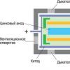
Daylight fixtures use the ability of mercury vapor to emit infrared waves when exposed to electricity. In the range visible to our eyes, this radiation is transferred by phosphor substances.
Therefore, an ordinary fluorescent lamp is a glass bulb, the walls of which are covered with a phosphor. There is also some mercury inside. There are two tungsten electrodes providing electron emission and heating (vaporization) of mercury. The flask is filled with an inert gas, most often argon. Glow starts when mercury vapor is heated to a certain temperature.

But for the evaporation of mercury, normal mains voltage is not enough. To start work, in parallel with the electrodes, start-regulating devices (abbreviated as ballast) are turned on. Their task is to create a short-term voltage surge necessary for the onset of glow, and then limit the operating current, preventing it from increasing uncontrollably. These devices - ballasts - are of two types - electromagnetic and electronic. Accordingly, the schemes are different.
Starter circuits
The very first circuits with starters and chokes appeared. These were (and in some versions are) two separate devices, each of which had its own socket. There are also two capacitors in the circuit: one is connected in parallel (to stabilize the voltage), the second is located in the starter housing (increases the duration of the starting pulse). All this "economy" is called electromagnetic ballast. A diagram of a fluorescent lamp with a starter and a choke is shown in the photo below.

Connection diagram for fluorescent lamps with a starter
This is how it works:
- When the power is turned on, the current flows through the inductor and goes to the first tungsten coil. Further, through the starter, it enters the second spiral and leaves through the zero conductor. At the same time, the tungsten filaments gradually heat up, as do the starter contacts.
- The starter consists of two contacts. One is fixed, the second is movable bimetallic. They are normally open. When current flows, the bimetallic contact heats up, which leads to the fact that it bends. Bent over, it connects to a fixed contact.
- As soon as the contacts are connected, the current in the circuit instantly rises (2-3 times). It is limited only by the throttle.
- Due to a sharp jump, the electrodes are very quickly heated.
- The bimetallic plate of the starter cools down and breaks the contact.
- At the moment of contact breakage, a sharp voltage jump occurs across the inductor (self-induction). This voltage is enough for the electrons to break through the argon medium. Ignition occurs and gradually the lamp enters the operating mode. It occurs after all the mercury has evaporated.
The operating voltage in the lamp is lower than the mains voltage for which the starter is designed. Therefore, after ignition, it does not work. In a working lamp, his contacts are open and he does not participate in its work in any way.
This circuit is also called electromagnetic ballast (EMB), and the operating circuit of the electromagnetic ballast is called EMCP. This device is often referred to simply as a choke.

One of the EMPRA
The disadvantages of this scheme for connecting a fluorescent lamp are enough:
- pulsating light, which negatively affects the eyes and they quickly get tired;
- noises during start-up and operation;
- impossibility of starting at a low temperature;
- long start - from the moment of switching on, about 1-3 seconds pass.
Two tubes and two chokes
In luminaires for two fluorescent lamps, two sets are connected in series:
- the phase wire is fed to the choke input;
- from the output of the throttle goes to one contact of the lamp 1, from the second contact goes to the starter 1;
- from the starter 1 goes to the second pair of contacts of the same lamp 1, and the free contact is connected to the zero power wire (N);
The second tube is also connected: first the throttle, from it - to one contact of the lamp 2, the second contact of the same group goes to the second starter, the starter output is connected to the second pair of contacts of the lighting device 2 and the free contact is connected to the zero input wire.

Connection diagram for two fluorescent lamps
The same connection diagram for a two-lamp daylight lamp is shown in the video. It may be easier to deal with the wires this way.
Wiring diagram for two lamps from one choke (with two starters)
Practically the most expensive in this circuit are chokes. You can save money and make a two-lamp luminaire with one choke. How - see the video.
Electronic ballast
All the shortcomings of the scheme described above stimulated research. As a result, an electronic ballast circuit was developed. It does not transmit the mains frequency of 50Hz, but high-frequency vibrations (20-60 kHz), thereby removing the blinking light, which is very unpleasant for the eyes.

One of the electronic ballasts - electronic ballasts
The electronic ballast looks like a small block with removed terminals. Inside there is one printed circuit board on which the entire circuit is assembled. The unit has small dimensions and is mounted in the body of even the smallest luminaire. The parameters are selected so that the start-up is quick, silent. No more devices are needed to work. This is the so-called non-starter switching circuit.
Each device has a diagram on the back. From it it is immediately clear how many lamps are connected to it. The information is also duplicated in the labels. Indicates the power of the lamps and their number, as well as the technical characteristics of the device. For example, the block in the photo above can only serve one lamp. Its connection diagram is on the right. As you can see, there is nothing complicated. Take the wires, connect them with conductors with the indicated contacts:
- connect the first and second contacts of the block output to one pair of lamp contacts:
- serve the third and fourth for another pair;
- supply power to the entrance.
Everything. The lamp is working. The circuit for switching on two fluorescent lamps to electronic ballasts is not much more complicated (see the diagram in the photo below).

The advantages of electronic ballasts are described in the video.
The same device is mounted in the base of fluorescent lamps with standard sockets, which are also called "economical lamps". This is a similar lighting fixture, only greatly modified.

The so-called "fluorescent light" (LDS) lamps are certainly more economical than conventional incandescent lamps, and they are much more durable. But, unfortunately, they have the same "Achilles heel" - the filaments. It is the heating coils that most often fail during operation - they simply burn out. And the lamp has to be thrown away, inevitably polluting the environment with harmful mercury. But not everyone knows that such lamps are still quite suitable for further work.
In order for the LDS, in which only one filament has burned out, to continue to work, it is enough just to bridge those pins of the lamp that are connected to the burned-out filament. It is easy to identify which thread is burnt out and which is intact with an ordinary ohmmeter or tester: a burned-out thread will show infinitely high resistance on the ohmmeter, but if the thread is intact, the resistance will be close to zero. In order not to fiddle with soldering, several layers of foil (from a tea wrapper, milk bag or cigarette package) paper are strung on the pins coming from the burnt thread, and then the entire “puff pie” is carefully cut with scissors along the diameter of the lamp base. Then the LDS connection diagram will turn out as shown in Fig. 1. Here fluorescent lamp EL1 has only one (left according to the scheme) whole filament, while the second (right) is short-circuited by our improvised jumper. Other elements of the fluorescent lamp fittings - such as an L1 choke, a neon (with bimetallic contacts) starter EK1, as well as an interference suppression capacitor SZ (with a rated voltage of at least 400 V), may remain the same. True, the ignition time of the LDS with such a modified scheme can increase up to 2 ... 3 seconds.
A simple circuit for switching on an LDS with one burned-out filament
The lamp works in such a situation like this. As soon as the mains voltage of 220 V is applied to it, the neon lamp of the EK1 starter lights up, due to which its bimetallic contacts heat up, as a result of which they eventually close the circuit, connecting the choke L1 - through a whole filament to the network. Now this remaining thread heats up the mercury vapor in the LDS glass flask. But soon the bimetallic contacts of the lamp cool down (due to the extinction of the "neon") so much that they open. Due to this, a high-voltage pulse is formed on the choke (due to the EMF of the self-induction of this inductor). It is he who is able to "set fire" the lamp, in other words, ionize the vapor of mercury. It is the ionized gas that causes the glow of the powder phosphor, which is covered from the inside along the entire length of the flask.
But what if both filaments burned out in the LDS? Of course, it is permissible to bridge the second thread, however, the ionization ability of a lamp without forced heating is significantly lower, and therefore a high-voltage pulse here will require a greater amplitude (up to 1000 V and more).
To reduce the voltage of "ignition" of the plasma, auxiliary electrodes can be arranged outside the glass bulb, as if in addition to the two existing ones. They can be an annular band glued to the flask with BF-2, K-88, Moment, etc. glue. A band about 50 mm wide is cut from copper foil. A thin wire is soldered to it with POS solder, electrically connected to the electrode of the opposite end of the LDS tube. Naturally, the top of the conductive belt is covered with several layers of PVC tape, "scotch tape" or medical adhesive plaster. A diagram of such a refinement is shown in Fig. 2. It is interesting that here (as in the usual case, that is, with whole filaments), it is not at all necessary to use a starter. So, the closing (normally open) button SB1 is used to turn on the EL1 lamp, and the opening (normally closed) button SB2 is used to turn off the LDS. Both of them can be of the type KZ, KPZ, KN, miniature MPK1-1 or KM1-1, etc.

LDS switching circuit with additional electrodes
In order not to bother winding up the conductive belts, which will not look very nice outwardly, collect the voltage quadrupler (Fig. 3). It will allow you to forget about the problem of burning out unreliable filaments once and for all.

A simple circuit for switching on an LDS with two burned-out filaments by means of a voltage quadrupler
The quadrupler contains two conventional voltage doubling rectifiers. So, for example, the first of them is assembled on capacitors C1, C4 and diodes VD1, VD3. Thanks to the action of this rectifier, a constant voltage of about 560V is formed on the capacitor SZ (since 2.55 * 220 V = 560 V). A voltage of the same magnitude appears on the capacitor C4, therefore, a voltage of about 1120 V appears on both capacitors C3, C4, which is quite sufficient for the ionization of mercury vapor inside the LDS EL1. But as soon as ionization began, the voltage across the capacitors C3, C4 decreases from 1120 to 100 ... 120 V, and on the current-limiting resistor R1 drops to about 25 ... 27 V.
It is important that paper (or even electrolytic oxide) capacitors C1 and C2 must be designed for a nominal (operating) voltage of at least 400 V, and mica capacitors C3 and C4 - 750 V or more. Powerful current limiting resistor R1 is best replaced with a 127-volt incandescent light bulb. The resistance of the resistor R1, its power dissipation, as well as 127-volt lamps suitable for power (they should be connected in parallel) are indicated in the table. It also contains data on the recommended VD1-VD4 diodes and the capacitance of C1-C4 capacitors for the LDS of the required power.
If a 127-volt lamp is used instead of a very heating resistor R1, its filament will barely glow - the filament heating temperature (at a voltage of 26 V) does not reach even 300 ° C (a dark brown color of heat, indistinguishable to the eye even in complete darkness). Because of this, 127-volt lamps can last almost forever here. They can only be damaged purely mechanically, say, by accidentally breaking a glass flask or "shaking off" a thin hair of the spiral. The 220-volt lamps would heat up even less, but their power would have to be taken too high. The fact is that it should exceed the LDS power by approximately 8 times!
Fluorescent lamps (LDS) are the first economical devices that appeared after traditional lamps with a filament. They belong to gas-discharge devices, where an element that limits the power in the electrical circuit is required.
Choke assignment
The fluorescent light choke controls the voltage applied to the lamp electrodes. In addition, it has the following assignments:
- protection against power surges;
- heating the cathodes;
- creating a high voltage to start the lamp;
- limiting the strength of the electric current after starting;
- stabilization of the lamp burning process.
To save money, the choke is connected to two lamps.
The principle of operation of an electromagnetic ballast (EMPRA)
The first one, which was created and is still used today, includes the elements:
- throttle;
- starter;
- two capacitors.
The fluorescent lamp circuit with a choke is connected to a 220 V network. All parts connected together are called an electromagnetic ballast.
When power is applied, the circuit of the tungsten spirals of the lamp is closed, and the starter is turned on in the glow discharge mode. The current does not pass through the lamp yet. The threads are gradually warming up. The starter contacts are initially open. One of them is bimetallic. It bends when heated from a glow discharge and completes the circuit. In this case, the current increases 2-3 times and the cathodes of the lamp are heated.
As soon as the contacts of the starter are closed, the discharge in it stops and begins to cool down. As a result, the movable contact opens and self-induction of the choke occurs in the form of a significant voltage pulse. It is enough for the electrons to penetrate the gaseous medium between the electrodes and the lamp ignites. The rated current begins to pass through it, which then decreases by 2 times due to the voltage drop across the choke. The starter permanently remains in the off state (contacts open) while the LDS is on.
Thus, the ballast starts the lamp and further maintains it in an active state.

Advantages and disadvantages of EMPRA
The electromagnetic choke for fluorescent lamps is characterized by low price, simple design and high reliability.
In addition, there are disadvantages:
- pulsating light, leading to eye fatigue;
- up to 15% electricity is lost;
- noises at the time of start-up and during operation;
- the lamp does not start well at low temperatures;
- large size and weight;
- long lamp start.
Usually, the buzzing and flickering of the lamp occurs when the power supply is unstable. Ballasts are produced with different noise levels. To reduce it, you can choose a suitable model.
Lamps and chokes are matched to each other in power, otherwise the life of the luminaire will be significantly reduced. Usually they are supplied in a set, and the ballast is replaced with a device with the same parameters.
Complete with EMPRA are inexpensive, and they do not require adjustment.
The ballast is characterized by the consumption of reactive energy. To reduce losses, a capacitor is connected in parallel with the power supply network.

Electronic ballast
All the shortcomings of the electromagnetic choke had to be eliminated, and as a result of research, an electronic choke for fluorescent lamps (ECG) was created. The circuit is a single block that starts and maintains the combustion process by forming a predetermined sequence of voltage changes. You can connect it using the instructions supplied with the model.
The choke for fluorescent lamps of electronic type has the following advantages:
- the ability to start instantly or with any delay;
- lack of a starter;
- lack of blinking;
- increased light output;
- compactness and lightness of the device;
- optimal operating modes.
Electronic ballasts are more expensive than an electromagnetic device due to the complex electronic circuitry that includes filters, power factor correction, inverter and ballast. In some models, protection against erroneous starting of the luminaire without lamps is installed.
User reviews say about the convenience of using electronic ballasts in energy-saving LDS, which are built directly into the bases for conventional standard cartridges.

How to start a fluorescent lamp using an electronic ballast?
When switched on, voltage is applied to the electrodes from the electronic ballast, and they are warmed up. Then they receive a powerful pulse that ignites the lamp. It is formed by creating an oscillatory circuit entering into resonance before the discharge. In this way, the cathodes are well heated, all the mercury in the bulb evaporates, due to which the lamp starts up easily. After the discharge occurs, the resonance of the oscillatory circuit immediately stops and the voltage drops to the working one.
The principle of operation of an electronic ballast is similar to the version with an electromagnetic choke, since the lamp starts up, which then decreases to a constant value and maintains the discharge in the lamp.
The current frequency reaches 20-60 kHz, due to which flicker is excluded, and the efficiency becomes higher. Reviews often suggest replacing electromagnetic chokes with electronic ones. It is important that they are suitable in terms of power. The circuit can create an instant start or a gradual increase in brightness. It is convenient to make a cold start, but the service life of the luminaire becomes much shorter.

Daytime running light without starter, throttle
LDS can be switched on without a bulky choke, using a simple incandescent lamp with a similar power instead. In this scheme, a starter is also not needed.
The connection is made through a rectifier, in which the voltage is doubled using capacitors and ignites the lamp without heating the cathodes. In series with the LDS through the phase wire, an incandescent lamp is turned on, limiting the current. Capacitors and diodes of the rectifier bridge should be selected with a margin of allowable voltage. When the LDS is fed through a rectifier, the flask on one side will soon begin to darken. In this case, the polarity of the power supply must be reversed.
Daylight without a choke, where an active load is applied instead, gives a weak brightness.
If a choke is installed instead of an incandescent lamp, the lamp will glow much more strongly.

Checking throttle serviceability
When the LDS is off, the reason lies in a malfunction of the electrical wiring, the lamp itself, the starter or the choke. Simple reasons are identified by the tester. Before checking the fluorescent lamp choke with a multimeter, disconnect the voltage and discharge the capacitors. Then the switch of the device is set to the continuity mode or to the minimum resistance measurement limit and the following are determined:
- the integrity of the coil winding;
- electrical resistance of the winding;
- turn-to-turn closure;
- open circuit in the coil winding.
The reviews suggest checking the choke by connecting it to the network through an incandescent lamp. When it burns brightly, and when it is in good condition, it is full.
If a malfunction is found, the throttle is easier to replace, as repairs can be more expensive.
Most often, the starter fails in the circuit. To check its performance, a knowingly working one is connected instead of it. If the lamp does not light up, then the reason is different.
The choke is also checked using a working lamp by connecting two wires from it to its base. If the lamp lights up brightly, then the choke is operational.
Conclusion
The fluorescent lamp choke is being improved in the direction of improving technical characteristics. Electronic devices are beginning to supplant electromagnetic ones. At the same time, old versions of the models continue to be used due to their simplicity and low price. It is necessary to understand all the variety of types, properly operate and connect them.
I have said more than once that many things that surround us could have been implemented much earlier, but for some reason they entered our life quite recently. We have all come across fluorescent lamps - those white tubes with two pins at the ends. Remember how they used to turn on? You press a key, the lamp starts blinking and finally enters its normal mode. It was really annoying, so they didn't put such things at home. They were installed in public places, in production, in offices, in the shops of factories - they are really economical compared to conventional incandescent lamps. They just blinked at a frequency of 100 times per second and many noticed this blinking, which annoyed me even more. Well, to start, each lamp relied on a control valve, such a piece of iron with a mass of under a kilogram. If it was not assembled well enough, then it buzzed rather disgustingly, also with a frequency of 100 hertz. And if there are dozens of such lamps in the room where you work? Or hundreds? And all these dozens are switched on and off in phase 100 times per second and the chokes are buzzing, though not all. Didn't it have any effect?
But, in our time, we can say that the era of humming chokes and blinking (both at start and during operation) lamps is over. Now they turn on immediately and to the human eye their work looks completely static. The reason is that instead of heavy chokes and periodically sticking starters, electronic ballasts - electronic ballasts - came into circulation. Small and lightweight. However, at just one glance at their electrical circuit, the question arises: what prevented their mass production from being established back in the late 70s and early 80s? After all, the entire element base was already then. Actually, in addition to two high-voltage transistors, the simplest parts are involved there, literally of a penny cost, which were also in the 40s. Well, okay, the USSR, here production reacted poorly to technical progress (for example, tube TVs were discontinued only at the end of the 80s), but in the West?
So, in order ...
The standard scheme for switching on a fluorescent lamp, like almost everything in the twentieth century, was invented by the Americans on the eve of World War II and included, in addition to the lamp, the choke and starter that we already mentioned. Yes, they also hung a capacitor in parallel with the network to compensate for the phase shift introduced by the inductor or, in even simpler terms, to correct the power factor.
Chokes and starters
 |
The principle of the whole system is pretty tricky. At the moment the power button closes along the network-button-choke-first spiral-starter-second spiral-network circuit, a weak current begins to flow - approximately 40-50 mA. Weak because at the initial moment the resistance of the gap between the starter contacts is large enough. However, this weak current causes ionization of the gas between the contacts and begins to increase sharply. From this, the starter electrodes are heated, and since one of them is bimetallic, that is, it consists of two metals with different dependences of changes in geometric parameters on temperature (different coefficient of thermal expansion - CTE), then when heated, the bimetal plate bends towards the metal with a lower CTE and closes with a different electrode. The current in the circuit increases sharply (up to 500-600 mA), but still its growth rate and final value are limited by the inductance of the inductor, the inductance itself is the property of preventing the instantaneous inductance of the current. Therefore, the choke in this circuit is officially called "ballast". This high current heats up the spirals of the lamp, which begin to emit electrons and heat up the gas mixture inside the cylinder. The lamp itself is filled with argon and mercury vapor - this is an important condition for a stable discharge. It goes without saying that when the contacts are closed in the starter, the discharge in it stops. This entire process actually takes a split second.
| |
Now the fun begins. The cooled starter contacts open. But the choke has already stored energy equal to half the product of its inductance and the square of the current. It cannot instantly disappear (see above about inductance), and therefore causes the appearance of an EMF of self-induction in the inductor (in other words, a voltage pulse of about 800-1000 volts for a 36-watt lamp 120 cm long). Adding to the peak mains voltage (310 V), it creates a voltage on the lamp electrodes sufficient for breakdown - that is, for a discharge to occur. The discharge in the lamp creates an ultraviolet glow of mercury vapor, which in turn affects the phosphor and makes it glow in the visible spectrum. At the same time, we remind you once again that the inductive resistance of the choke prevents an unlimited increase in the current in the lamp, which would lead to its destruction or the operation of a circuit breaker in your home or other place where similar lamps are used. Note that the lamp does not always light up the first time, sometimes it takes several attempts for it to enter a stable glow mode, that is, the processes that we have described are repeated 4-5-6 times. Which is really quite unpleasant. After the lamp has entered the glowing mode, its resistance becomes much lower than the resistance of the starter, so it can be pulled out, while the lamp will continue to glow. Well, also, if you disassemble the starter, you will see that a capacitor is connected in parallel to its terminals. It is needed to attenuate the radio interference created by the contact.
So, if very briefly and without going into theory, let's say that a fluorescent lamp is turned on with a high voltage, but it is kept in a luminous state much less (for example, it turns on at 900 volts, glows at 150). That is, any device for turning on a fluorescent lamp is a device that creates a high turn-on voltage at its ends, and after lighting the lamp, it reduces it to a certain operating value.
This American switching scheme was actually the only one, and only 10 years ago its monopoly began to collapse rapidly - Electronic ballasts entered the market en masse. They made it possible not only to replace heavy humming throttles, to ensure instantaneous switching on of the lamp, but also to introduce a lot of other useful things, such as:
- soft start of the llama - preliminary heating of the spirals, which dramatically increases the lamp life
- overcoming flicker (lamp power frequency is much higher than 50 Hz)
- Wide range of input voltage 100 ... 250 V;
- reduction of energy consumption (up to 30%) with a constant luminous flux;
- increase in average lamp life (by 50%);
- protection against power surges;
- ensure the absence of electromagnetic interference;
- O no inrush currents (important when many lamps are switched on at the same time)
- automatic shutdown of defective lamps (this is important, devices are often afraid of idling)
- Efficiency of high-quality electronic ballasts - up to 97%
- regulation of brightness of lamps
But! All these sweets are realized only in expensive electronic ballasts. And in general, not everything is so cloudless. More precisely - maybe everything would be cloudless if the EPR schemes were made truly reliable. After all, it seems obvious that an electronic ballast (electronic ballast) should in any case be no less reliable than a choke, especially if it costs 2-3 times more. In the "former" circuit consisting of a choke, a starter and the lamp itself, it was precisely the choke (ballast) that was the most reliable and, in general, with a high-quality assembly, it could work almost forever. Soviet chokes of the 60s still work, they are large and wound with a rather thick wire. Imported chokes of similar parameters, even of such well-known companies as Philips, do not work so reliably. Why? The very thin wire with which they are wound is suspicious. Well, the core itself is much smaller in volume than that of the first Soviet chokes, which is why these chokes get very hot, which probably also affects reliability.
Yes, so, as it seems to me, electronic ballasts, at least cheap - that is, costing up to $ 5-7 per piece (which is higher than that of the throttle), are made deliberately unreliable. No, they can work for years and may even work forever, but here, like in the lottery, the probability of losing is much higher than winning. Expensive electronic ballasts are made conditionally reliable. We will tell you why "conditionally" a little later. Let's start our little review with cheap ones. As for me, they make up 95% of the purchased ballasts. And maybe almost 100%.
Let's consider several such schemes. By the way, all "cheap" schemes are practically the same in design, although there are some nuances.
 |
Cheap electronic ballasts (ECG). 95% of sales.
Ballasts of this type, costing 3-5-7 dollars, simply include a lamp. This is their only function. They have no other useful bells and whistles. I sketched a couple of diagrams to explain how this newfangled miracle works, although as we said above, the principle of operation is the same as in the "classic" throttle version - we ignite with high voltage, keep it low. But it is only implemented in a different way.
 |
All circuits of electronic ballasts (ECG) that I held in my hands - both cheap and expensive - were a half-bridge - only control options and "strapping" differed. So, the alternating voltage of 220 volts is rectified by the diode bridge VD4-VD7 and smoothed by the capacitor C1. In the input filters of cheap electronic ballasts, due to cost and space savings, small capacitors are used, on which the magnitude of the voltage ripple with a frequency of 100 Hz depends, moreover, the calculation is approximately as follows: 1 watt of a lamp - 1 μF of the filter capacitance. In this circuit, 5.6 microfarads per 18 watts, that is, clearly less than necessary. That is why (although not only because of this), by the way, the lamp glows visually dimmer than from an expensive ballast for the same power.
Further, through the high-resistance resistor R1 (1.6 MΩ), capacitor C4 begins to charge. When the voltage across it exceeds the operation threshold of the bidirectional dinistor CD1 (about 30 volts), it breaks down and a voltage pulse appears at the base of the transistor T2. Opening the transistor starts the operation of the half-bridge auto-generator formed by the transistors T1 and T2 and the transformer TR1 with the control windings turned on in antiphase. Usually these windings contain 2 turns, and the output winding contains 8-10 turns of wire.
Diodes VD2-VD3 extinguish negative surges arising on the windings of the control transformer.
So, the generator starts at a frequency close to the resonant frequency of the series circuit formed by the capacitors C2, C3 and the choke C1. This frequency can be equal to 45-50 kHz, in any case, I could not measure it more accurately, I did not have a storage oscilloscope at hand. Note that the capacitance of the capacitor C3 connected between the electrodes of the lamp is about 8 times less than the capacitance of the capacitor C2, therefore, the voltage jump on it is as many times higher (since the capacitive resistance is 8 times greater - the higher the frequency, the greater the capacitive resistance on a smaller capacity). That is why the voltage of such a capacitor is always chosen at least 1000 volts. At the same time, a current flows along the same circuit, heating the electrodes. When the voltage across the capacitor C3 reaches a certain value, a breakdown occurs and the lamp lights up. After ignition, its resistance becomes much lower than the resistance of the capacitor C3 and it has no effect on further work. The generator frequency is also reduced. The L1 choke, as in the case of the "classic" choke, now performs the function of limiting the current, but since the lamp operates at a high frequency (25-30 kHz), its dimensions are many times smaller.
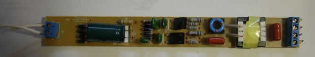
Ballast appearance. It can be seen that some elements are not soldered to the board. For example, where I soldered a current-limiting resistor after repair, there is a wire jumper.
Another product. Unknown manufacturer. 2 diodes were not sacrificed here to make an "artificial zero".
 |
|
"Sevastopol scheme"
There is an opinion that no one will do it cheaper than the Chinese will do. I was sure of that too. I am sure until I got my hands on the electronic ballasts of a certain "Sevastopol plant" - in any case, the person who sold them said exactly that. They were designed for a 58 W lamp, that is, 150 cm long. No, I will not say that they did not work or worked worse than the Chinese ones. They worked. The lamps shone from them. But…
Even the cheapest Chinese ballasts (electronic ballasts) are a plastic case, a board with holes, a mask on the board from the printed circuit side and a designation - where is which part from the mounting side. The "Sevastopol variant" was deprived of all these redundancies. There the board was at the same time the cover of the case, there were no holes in the board (for this reason), there were no masks, no markings, the parts were placed on the side of the printed conductors and everything that could be made of SMD elements, which I have never not seen even in the cheapest Chinese devices. Well, the circuit itself! I have reviewed a great many of them, but have never seen anything like it. No, everything seems to be like that of the Chinese: an ordinary half-bridge. Here are just the purpose of the elements D2-D7 and the strange connection of the base winding of the lower transistor is absolutely incomprehensible to me. And further! The creators of this miracle device combined a half-bridge generator transformer with a choke! They just wound the windings on the W-shaped core. Nobody thought of this, not even the Chinese. In general, this scheme was designed either by geniuses or alternatively gifted people. On the other hand, if they are so ingenious, why not donate a couple of cents to introduce a current limiting resistor to prevent the surge of current through the filter capacitor? And on the varistor for smooth heating of the electrodes (also cents) - they could go broke.
IN USSR
The above "American circuit" (choke + starter + fluorescent lamp) operates on an alternating current with a frequency of 50 hertz. And if the current is constant? Well, for example, the lamp must be powered by batteries. Here you can't do with an electromechanical option. It is necessary to "sculpt the scheme." Electronic. And such schemes were, for example, on trains. We all traveled in Soviet carriages of varying degrees of comfort and saw these fluorescent tubes there. But they were powered by a direct current with a voltage of 80 volts, such a voltage is given by a car battery. For the power supply, the "same" circuit was developed - a half-bridge generator with a series resonant circuit, and to prevent current surges through the lamp spirals, a direct heating thermistor TRP-27 with a positive temperature coefficient of resistance was introduced. The circuit, I must say, was distinguished by exceptional reliability, and in order to convert it into ballast for an alternating current network and use it in everyday life, it was essentially necessary to add a diode bridge, a smoothing capacitor and a little recalculate the parameters of some parts and a transformer. The only "but". Such a contraption would be quite expensive. I think its cost would be at least 60-70 Soviet rubles, with a choke cost of 3 rubles. Basically, due to the high cost in the USSR of powerful high-voltage transistors. And this circuit also emitted a rather unpleasant high-frequency squeak, not always, but sometimes it could be heard, perhaps over time the parameters of the elements changed (capacitors dried up) and the frequency of the generator decreased.
The power circuit for fluorescent lamps in trains in good resolution
 |
Expensive electronic ballasts (ECG)
An example of a simple "expensive" ballast is a TOUVE product. He worked in the aquarium lighting system, in other words, two 36-watt green lamas were powered by him. The ballast owner told me that this is something special, specially designed for lighting aquariums and terrariums. "Eco-friendly". What is environmental friendliness, I still did not understand, another thing is that this "environmental ballast" did not work. An autopsy and analysis of the circuit showed that, compared with cheap ones, it is significantly complicated, although the principle - half-bridge + starting through the same DB3 dinistor + serial resonant circuit - is preserved in full. Since there are two lamps, we see two resonant circuits T4C22C2 and T3C23C5. Cold spirals of lamps from current surge protect thermistors PTS1, PTS2.
Rule! If you are buying an economical lamp or here is an electronic ballast, check how this very lamp turns on. If instantly - the ballast is cheap, no matter what they tell you about it. In more or less normal, the lamp should turn on after pressing the button after about 0.5 seconds.
Farther. The input varistor RV protects the power supply filter capacitors from inrush current. The circuit is equipped with a power filter (circled in red) - it prevents high-frequency noise from entering the network. The Power Factor Correction is circled in green, but in this circuit it is assembled on passive elements, which distinguishes it from the most expensive and sophisticated ones, where the correction is controlled by a special microcircuit. We will talk about this important problem (power factor correction) in one of the following articles. Well, the protection unit in abnormal modes has also been added - in this case, the generation stops by shorting the SCR base Q1 to ground.
For example, deactivation of the electrodes or violation of the tightness of the tube lead to the emergence of an "open circuit" (the lamp does not light up), which is accompanied by a significant increase in the voltage across the starting capacitor and an increase in the ballast current at the resonance frequency, limited only by the Q-factor of the circuit. Long-term operation in this mode leads to damage to the ballast due to overheating of the transistors. In this case, the protection should work - the SCR thyristor closes the base of Q1 to ground, stopping the generation.
 |
It can be seen that this device is much larger in size than cheap ballasts, but after repair (one of the transistors flew out) and restoration, it turned out that these very transistors heat up, as it seemed to me, more than necessary, to about 70 degrees. Why not put in small radiators? I am not saying that the transistor flew out due to overheating, but it is possible that work at elevated temperatures (in a closed case) served as a provoking factor. In general, I put small radiators, since there is a place.