Greetings, dear friends! Today we will focus on bipolar transistors and the information will be useful primarily for beginners. So, if you are wondering what a transistor is, its principle of operation and in general what it is eaten with, then we take a chair for more comfortable and come closer.
Let's continue, and we have the content here, it will be more convenient to navigate the article 🙂
Types of transistors
There are basically two types of transistors: bipolar transistors and field-effect transistors. Of course, you could consider all types of transistors in one article, but I don't want to cook porridge in your head. Therefore, in this article we will consider exclusively bipolar transistors and I will talk about field-effect transistors in one of the following articles. We will not mix everything in one heap, but we will pay attention to each, individually.
Bipolar transistor
The bipolar transistor is a descendant of the tube triodes used in 20th century televisions. Triodes went into oblivion and gave way to more functional brothers - transistors, or rather bipolar transistors.
Triodes, with rare exceptions, are used in equipment for music lovers.
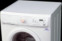
Bipolar transistors might look like this.

As you can see, bipolar transistors have three leads and they can look completely different in design. But on electrical diagrams they look simple and always the same. And all this graphic splendor looks something like this.
 This image of transistors is also called UGO (Conditional graphic designation).
Moreover, bipolar transistors can have a different type of conductivity. There are transistors of NPN type and PNP type.
The difference between an n-p-n transistor and a p-n-p transistor is that it is a "carrier" of an electric charge (electrons or "holes"). Those. for a pnp transistor, electrons move from the emitter to the collector and are driven by the base. For an npn transistor, electrons go from the collector to the emitter and are controlled by the base. As a result, we come to the conclusion that in order to replace a transistor of one type of conductivity in the circuit with another, it is enough to change the polarity of the applied voltage. Or it is stupid to change the polarity of the power source.
Bipolar transistors have three leads: collector, emitter, and base. I think that it will be difficult to get confused according to UGO, but in a real transistor it is as easy as shelling pears to get confused.
Usually, where what output is determined by the directory, but you can simply. The terminals of the transistor ring like two diodes connected at a common point (in the area of the base of the transistor).
On the left is a picture for a p-n-p type transistor, when dialing, it feels like (through the readings of a multimeter) that you have two diodes in front of you that are connected at one point by their cathodes. For transistor n-p-n type diodes at the base point are connected by their anodes. I think after experimenting with a multimeter it will be more clear.

The principle of operation of a bipolar transistor
And now we will try to figure out how the transistor works. I will not go into details internal device transistors as this information only confuses. Better take a look at this picture. 
This image best explains how the transistor works. In this image, a person, through a rheostat, controls the collector current. He looks at the base current, if the base current rises, then the person also increases the collector current, taking into account the gain of the transistor h21E. If the base current drops, then the collector current will also decrease - the person will correct it by means of a rheostat.
This analogy has nothing to do with real work transistor, but it makes it easier to understand the principles of its operation.
For transistors, rules can be noted to help facilitate understanding. (These rules are taken from the book).
- The collector has a more positive potential than the emitter
- As I said, the base-collector and base-emitter circuits work like diodes.
- Each transistor has limits such as collector current, base current, and collector-emitter voltage.
- In the event that rules 1-3 are observed, then the collector current Ik is directly proportional to the base current Ib. This ratio can be written as a formula.
![]()
From this formula, the main property of the transistor can be expressed - a small base current controls a large collector current.
Current gain.
It is also referred to as
Based on the above, the transistor can operate in four modes:
- Transistor cutoff mode- in this mode, the base-emitter junction is closed, this can happen when the base-emitter voltage is insufficient. As a result, there is no base current and therefore no collector current.
- Active transistor mode- this is the normal operating mode of the transistor. In this mode, the base-emitter voltage is sufficient for the base-emitter junction to open. The base current is sufficient and the collector current is also available. The collector current is equal to the base current multiplied by the gain.
- Transistor saturation mode - the transistor switches to this mode when the base current becomes so large that the power of the power supply is simply not enough to further increase the collector current. In this mode, the collector current cannot increase following an increase in the base current.
- Inverse transistor mode- this mode is used extremely rarely. In this mode, the collector and emitter of the transistor are swapped. As a result of such manipulations, the gain of the transistor suffers greatly. The transistor was not originally designed to operate in such a special mode.
To understand how a transistor works, you need to consider specific circuit examples, so let's look at some of them.
Transistor in key mode
The transistor in the switch mode is one of the cases of transistor circuits with a common emitter. The transistor circuit in the key mode is used very often. This transistor circuit is used for example when it is necessary to control a powerful load by means of a microcontroller. The controller leg is not capable of pulling a powerful load, but the transistor can. It turns out the controller controls the transistor, and the transistor controls the powerful load. Well, first things first.
The main point of this mode is that the base current controls the collector current. Moreover, the collector current is much higher than the base current. Here, with the naked eye, you can see that there is an increase in the current signal. This amplification is carried out by the energy of the power source.
The figure shows a diagram of the operation of the transistor in the key mode.

For transistor circuits, voltages do not play a big role, only currents are important. Therefore, if the ratio of collector current to base current is less than the gain of the transistor, then everything is okay.
In this case, even if a voltage of 5 volts is applied to the base and 500 volts in the collector circuit, then nothing terrible will happen, the transistor will dutifully switch the high-voltage load.
The main thing is that these voltages do not exceed the limit values for a particular transistor (set in the characteristics of the transistor).
As far as we know, the current value is a characteristic of the load.
We do not know the resistance of the bulb, but we know the operating current of the bulb is 100mA. In order for the transistor to open and ensure the flow of such a current, you need to select the appropriate base current. We can adjust the base current by changing the value of the base resistor.
Since the minimum value of the transistor gain is 10, the base current must be 10 mA to open the transistor.
 The current we need is known. The voltage across the base resistor will be This value of the voltage across the resistor was obtained due to the fact that 0.6V-0.7V is deposited at the base-emitter junction, and this must not be forgotten to take into account.
As a result, we may well find the resistance of the resistor
 It remains to choose a specific value from a number of resistors and the trick is in the bag.
Now you probably think that the transistor switch will work as it should? That when the base resistor is connected to +5 V the light comes on, when the light turns off? The answer may or may not be yes.
The thing is that there is a small nuance here.
The light will go out when the potential of the resistor is equal to the potential of the ground. If the resistor is simply disconnected from the voltage source, then everything is not so simple here. The voltage across the base resistor can occur miraculously as a result of interference or some otherworldly evil 🙂
To prevent this effect from happening, do the following. Another resistor Rbe is connected between the base and the emitter. This resistor is chosen with a nominal value of at least 10 times the base resistor Rb (In our case, we took a 4.3kΩ resistor).
When the base is connected to any voltage, then the transistor works as it should, the resistor Rbe does not interfere with it. This resistor consumes only a small fraction of the base current.
In the case when no voltage is applied to the base, the base is pulled up to the ground potential, which saves us from all kinds of interference.
Here, in principle, we figured out the operation of the transistor in the key mode, and as you could see, the key mode of operation is a kind of voltage signal amplification. After all, we controlled a voltage of 12 V using a low voltage of 5V.
Emitter follower
The emitter follower is a special case of common collector transistor circuits.

A distinctive feature of a common-collector circuit from a common-emitter circuit (a variant with a transistor switch) is that this circuit does not amplify the voltage signal. What went in through the base came out through the emitter, with the same voltage.
Indeed, let's say we applied 10 volts to the base, while we know that at the base-emitter junction, somewhere between 0.6-0.7V is deposited. It turns out that at the output (at the emitter, at the load Rн) there will be a base voltage minus 0.6V.
It turned out 9.4V, in a word, almost as much was included and it turned out. We made sure that this circuit will not increase the signal to us in voltage.
“What is the point, then, such turning on the transistor?” - you ask. But it turns out that this scheme has another very important property. The switching circuit of a transistor with a common collector amplifies the signal in terms of power. Power is the product of current and voltage, but since the voltage does not change, power increases only due to current! ![]() The load current is the sum of the base current plus the collector current. But if you compare the base current and the collector current, then the base current is very small compared to the collector current. It turns out the load current is equal to the collector current. And the result is this formula.
The load current is the sum of the base current plus the collector current. But if you compare the base current and the collector current, then the base current is very small compared to the collector current. It turns out the load current is equal to the collector current. And the result is this formula.
Now I think it's clear what the essence of the emitter follower circuit is, but that's not all.
The emitter follower has another very valuable quality - high input impedance. This means that this transistor circuit draws almost no input signal current and does not load the signal source circuit.
To understand the principle of operation of the transistor, these two transistor circuits will be quite enough. And if you still experiment with a soldering iron in your hands, then the insight will simply not keep you waiting, because theory is theory and practice and personal experience are hundreds of times more valuable!
Where to buy transistors?
Like all other radio components, transistors can be bought at any nearest radio component store. If you live somewhere on the outskirts and have not heard of such stores (as I did before), then the last option remains - to order transistors in an online store. I myself often order radio parts through online stores, because in a regular offline store something may simply not be there.
However, if you are assembling a device purely for yourself, then you can not take a steam bath but get it from the old one, and so to speak breathe new life into the old radio component.
Well friends, that's all for me. Today I told you everything that I had planned. If you have any questions, then ask them in the comments, if there are no questions, then write comments anyway, your opinion is always important to me. By the way, do not forget that everyone who leaves a comment for the first time will receive a gift.
Also, be sure to subscribe to new articles, because a lot of interesting and useful things await you further.
I wish you good luck, success and a sunny mood!
With n / a Vladimir Vasiliev
P.S. Friends, be sure to subscribe to updates! By subscribing you will receive new materials directly to your mail! And by the way, every signer will receive a useful gift!
Graphic designation of radio components on the diagrams. Designation of radio components on the diagram and their name
| Designation | Name | Photo | Description |
| Earthing | Protective grounding - protects people from electric shock in electrical installations. | ||
| A battery is a galvanic cell in which chemical energy is converted into electrical energy. | |||
| The solar cell is used to convert solar energy into electrical energy. | |||
| Voltmeter - measuring device to determine the voltage or EMF in electrical circuits. | |||
| Ammeter - a device for measuring current strength, the scale is calibrated in microamperes or in amperes. | |||
| A switch is a switching device designed to turn on and off individual circuits or electrical equipment. | |||
| The tact button is a switching mechanism that closes the electrical circuit while there is pressure on the pusher. | |||
| Incandescent lamps general purpose, designed for indoor and outdoor lighting. | |||
| Motor (motor) - a device that converts electricity into mechanical work (rotation). | |||
| Piezodynamics (piezo emitters) are used in technology to notify an incident or event. | |||
| A resistor is a passive element of electrical circuits with a certain value of electrical resistance. | |||
| The variable resistor is designed for smooth change current, by changing its own resistance. | |||
| Photoresistor | A photoresistor is a resistor whose electrical resistance changes under the influence of light rays (lighting). | ||
| Thermistor | Thermistors or thermistors are semiconductor resistors with a negative temperature coefficient of resistance. | ||
| A fuse is an electrical device designed to disconnect a protected circuit by destroying it. | |||
| The capacitor serves to store the charge and energy of the electric field. The capacitor charges and discharges quickly. | |||
| The diode has different conductivity. The purpose of a diode is to conduct electric current in one direction. | |||
| A light-emitting diode (LED) is a semiconductor device that creates optical radiation when electricity is transmitted. | |||
| A photodiode is a receiver of optical radiation that converts light into electric charge due to the process in the p-n-junction. | |||
| A thyristor is a semiconductor switch, i.e. a device whose purpose is to close and open a circuit. | |||
| The purpose of the zener diode is to stabilize the voltage across the load, with a changing voltage in the external circuit. | |||
| A transistor is a semiconductor device designed to amplify and control an electric current. | |||
| A phototransistor is a semiconductor transistor that is sensitive to the luminous flux (illumination) that irradiates it. |
xn - 18-6kcdusowgbt1a4b.xn - p1ai
For Beginners About Radio Parts | Master Cog. Do it yourself!
In order to assemble the circuit, what kind of radio components are not needed: resistors (resistances), transistors, diodes, capacitors, etc. From the variety of radio components, one must be able to quickly distinguish the required one in appearance, decipher the inscription on its body, determine the pinout. All this will be discussed below.
This detail is practically found in every scheme of amateur radio designs. As a rule, the simplest capacitor is two metal plates (plates) and air between them as a dielectric. Instead of air, there can be porcelain, mica, or other non-conductive material. Direct current does not pass through the capacitor, but the alternating current passes through the capacitor. Due to this property, the capacitor is placed where it is necessary to separate the direct current from the alternating current.
For a capacitor, the main parameter is capacity.
The unit of capacity - microfarad (μF) is taken as a basis in radio amateur designs and in industrial equipment. But more often another unit is used - picofarad (pF), a millionth of a microfarad (1 microfarad = 1,000 nf = 1,000,000 pf). In the diagrams, you will find both the one and the other unit. Moreover, capacities up to 9100 pF inclusive are indicated on the circuits in picofarads or nanofarads (9n1), and above - in microfarads. If, for example, next to the condenser symbol is written "27", "510" or "6800", then the capacitance of the capacitor is respectively 27, 510, 6800 pF or n510 (0.51 nF = 510 pF or 6n8 = 6.8 nF = 6800pf). But the numbers 0.015, 0.25 or 1.0 indicate that the capacitance of the capacitor is the corresponding number of microfarads (0.015 microfarads = 15 nf = 15,000 pf).
Types of capacitors.
Capacitors are of constant and variable capacitance.
In variable capacitors, the capacitance changes when the axis protruding outward rotates. In this case, one pad (movable) finds it not movable without contacting it, as a result, the capacity increases. In addition to these two types, our designs use another type of capacitor - a trimmer. Usually it is installed in one or another device in order to more accurately select the required capacitance when setting up and not touch the capacitor anymore. In amateur designs, a trimmer capacitor is often used as a variable capacitor - it is cheaper and more affordable.

Capacitors differ in the material between the plates and the design. There are air, mica, ceramic, etc. capacitors. This type of permanent capacitors is not polar. Another type of capacitor is electrolytic (polar). Such capacitors produce large capacity- from a tenth of a microfarad to several tens of microfarads. On the diagrams for them, not only the capacity is indicated, but also the maximum voltage at which they can be used. For example, the inscription 10.0 x 25 V means that a capacitor with a capacity of 10 μF must be taken at a voltage of 25 V.
For variable or trimmer capacitors, the diagram indicates the extreme values of the capacitance, which are obtained if the axis of the capacitor is rotated from one extreme position to another or rotated round and round (like in trimmer capacitors). For example, the inscription 10 - 240 indicates that in one extreme position of the axis the capacitance of the capacitor is 10 pF, and in the other - 240 pF. With a smooth rotation from one position to another, the capacitance of the capacitor will also smoothly change from 10 to 240 pF or vice versa - from 240 to 10 pF.
I must say that this detail, like the capacitor, can be seen in many homemade products. It is a porcelain tube (or rod), on which the thinnest film of metal or soot (carbon) is sprayed on the outside. A nichrome thread is wound on top of low-resistance high-power resistors. A resistor has resistance and is used to set the desired current in an electrical circuit. Consider the example with the reservoir: by changing the pipe diameter (load resistance), you can get one or another water flow rate (electric current of different strength). The thinner the film on the porcelain tube or rod, the greater the resistance to current.
Resistors are constant and variable.
Of the constants, the most often used resistors are MLT (metallized varnished heat-resistant), VS (moisture-resistant resistance), ULM (small-sized carbon varnished), from variables - SP (variable resistance) and SPO (variable volumetric resistance). The appearance of fixed resistors is shown in Fig. below.

Resistors are distinguished by resistance and power. Resistance, as you already know, is measured in ohms (ohms), kilo-ohms (kohms) and megohms (megohms). Power is expressed in watts and this unit is denoted by the letters W. Resistors of different power differ in size. The higher the power of the resistor, the larger its size.
The resistance of the resistor is put on the diagrams next to its symbol. If the resistance is less than 1 kOhm, the numbers indicate the number of ohms without a unit of measurement. With a resistance of 1 kΩ or more - up to 1 MΩ, indicate the number of kilo-ohms and put the letter "k" next to it. Resistance of 1 megohm and above is expressed by the number of megohms with the addition of the letter "M". For example, if on the diagram next to the resistor designation 510 is written, then the resistance of the resistor is 510 ohms. The designations 3.6 k and 820 k correspond to resistances of 3.6 kΩ and 820 kΩ, respectively. The inscription on the diagram 1 M or 4.7 M means that resistances of 1 MΩ and 4.7 MΩ are used.
Unlike fixed resistors having two terminals, variable resistors have three such terminals. The diagram indicates the resistance between the extreme terminals of the variable resistor. The resistance between the middle terminal and the outermost ones changes with the rotation of the outwardly protruding axis of the resistor. Moreover, when the axis is turned in one direction, the resistance between the middle terminal and one of the extreme ones increases, respectively, decreasing between the middle terminal and the other extreme. When the axis is turned back, the opposite occurs. This property of a variable resistor is used, for example, to control the volume of sound in amplifiers, receivers, televisions, etc.
Semiconductor devices.
They are made up of a whole group of parts: diodes, zener diodes, transistors. Each part uses a semiconductor material, or more simply a semiconductor. What it is? All existing substances can be roughly divided into three large groups. Some of them - copper, iron, aluminum and other metals - conduct electric current well - these are conductors. Wood, porcelain, plastic do not conduct electricity at all. They are non-conductors, insulators (dielectrics). Semiconductors occupy an intermediate position between conductors and dielectrics. Such materials conduct current only under certain conditions.
A diode (see figure below) has two leads: an anode and a cathode. If you connect a battery to them with poles: plus - to the anode, minus - to the cathode, a current will flow in the direction from the anode to the cathode. The resistance of the diode in this direction is small. If you try to change the poles of the batteries, that is, turn on the diode "vice versa", then the current will not flow through the diode. In this direction, the diode has a high resistance. If you pass an alternating current through the diode, then at the output we will get only one half-wave - it will be a pulsating, but direct current. If an alternating current is applied to four diodes connected by a bridge, then we will already get two positive half-waves.

These semiconductors also have two leads: the anode and the cathode. In the forward direction (from the anode to the cathode), the zener diode works like a diode, allowing current to flow unhindered. But in the opposite direction, at first, it does not pass current (like a diode), and with an increase in the voltage supplied to it, it suddenly "breaks through" and begins to pass current. The breakdown voltage is called the stabilization voltage. It will remain unchanged even with a significant increase in the input voltage. Due to this property, the zener diode is used in all cases when it is necessary to obtain a stable supply voltage of some device during fluctuations, for example, the mains voltage.

Of the semiconductor devices, the transistor (see figure below) is most often used in electronics. It has three outputs: base (b), emitter (e) and collector (k). A transistor is an amplifying device. It can be conditionally compared with such a device known to you as a horn. It is enough to say something in front of the narrow opening of the horn, directing the wide one towards a friend standing several tens of meters away, and the voice amplified by the horn will be clearly heard in the distance. If we take a narrow hole as the input of a horn-amplifier, and a wide one as an output, then we can say that the output signal is several times larger than the input. This is an indicator of the amplifying ability of the speaker, its amplification factor.

Now the variety of manufactured radio components is very rich, therefore, not all of their types are shown in the figures.
But back to the transistor. If a weak current is passed through the base-emitter section, it will be amplified by the transistor tens and even hundreds of times. The amplified current will flow through the collector-emitter section. If the transistor is ringing the base-emitter and base-collector with a multimeter, then it is similar to measuring two diodes. Depending on the highest current that can be passed through the collector, transistors are divided into low-power, medium and high-power. In addition, these semiconductor devices can be structure p-p-p or n-p-p. This is how transistors differ with different alternation of layers of semiconductor materials (if there are two layers of material in a diode, there are three of them). The gain of a transistor is independent of its structure.
Literature: B. S. Ivanov, "ELECTRONIC DIY"

P O P U L Y R N O E:
>>
SHARE WITH FRIENDS:
Popularity: 29,094 views.
www.mastervintik.ru
RADIO ELEMENTS
This reference material provides appearance, name and marking of the main foreign radio components - microcircuits different types, connectors, quartz resonators, inductors and so on. The information is really useful, since many are well acquainted with domestic parts, but not very much with imported ones, and after all, they are the ones that are installed in all modern schemes. Minimum knowledge of English is encouraged, since all the inscriptions are not in Russian. For convenience, the details are grouped together. Do not pay attention to the first letter in the description, for example: f_Fuse_5_20Glass - means a 5x20 mm glass fuse.


As for the designation of all the indicated radioelements on electrical circuit diagrams - see reference information on this issue in another article.
Parts Forum
Discuss the article RADIO ELEMENTS
radioskot.ru
| AM | amplitude modulation |
| AFC | automatic frequency control |
| APCHG | automatic local oscillator frequency adjustment |
| APCHF | automatic frequency and phase adjustment |
| AGC | automatic gain control |
| ARYA | automatic brightness control |
| AS | acoustic system |
| AFU | antenna feeder |
| ADC | analog-to-digital converter |
| Frequency response | frequency response |
| BGIMS | large hybrid integrated circuit |
| NOS | wireless remote control |
| BIS | large integrated circuit |
| Biofeedback | signal processing unit |
| BP | power unit |
| BR | scanner |
| DBK | radio channel unit |
| BS | information block |
| BTK | blocking transformer personnel |
| BTS | blocking transformer lowercase |
| BOO | Control block |
| BC | color block |
| BCI | integrated chromaticity unit (using microcircuits) |
| VD | video detector |
| VIM | pulse time modulation |
| WU | video amplifier; input (output) device |
| HF | high frequency |
| G | heterodyne |
| GW | reproducing head |
| MHF | high frequency generator |
| MHF | hyperhigh frequency |
| GZ | start generator; recording head |
| GIR | heterodyne resonance indicator |
| GIS | hybrid integrated circuit |
| GKR | frame generator |
| GKCH | sweeping frequency generator |
| GMV | meter wave generator |
| GPA | smooth range generator |
| GO | envelope generator |
| HS | signal generator |
| GSR | line scan generator |
| gss | standard signal generator |
| yy | clock generator |
| GU | universal head |
| GUN | voltage controlled generator |
| D | detector |
| dv | long waves |
| dd | fractional detector |
| day | voltage divider |
| dm | power divider |
| dmv | decimeter waves |
| DU | remote control |
| DShPF | dynamic noise reduction filter |
| EASC | unified automated communication network |
| ESKD | one system design documentation |
| hr | sound frequency generator; master oscillator |
| ss | decelerating system; sound signal; pickup |
| ZCH | sound frequency |
| AND | integrator |
| iqm | pulse code modulation |
| IKU | quasi-peak level meter |
| ims | integrated circuit |
| ini | linear distortion meter |
| inc | infra-low frequency |
| and he | reference voltage source |
| sp | power supply |
| ichh | frequency response meter |
| To | switch |
| KBV | traveling wave ratio |
| Kv | short waves |
| kvh | extremely high frequency |
| kzv | recording-playback channel |
| Kim | pulse code modulation |
| kk | frame reel deflector |
| km | coding matrix |
| csch | extremely low frequency |
| efficiency | efficiency |
| KS | coil deflection line |
| csv | standing wave ratio |
| ksvn | voltage standing wave ratio |
| CT scan | check Point |
| CF | focusing coil |
| TWT | traveling wave lamp |
| lz | delay line |
| fishing | backward wave lamp |
| lpd | avalanche diode |
| lppt | tube semiconductor TV |
| m | modulator |
| MA | magnetic antenna |
| MB | meter waves |
| mdp | metal-dielectric-semiconductor structure |
| MNP | metal-oxide-semiconductor structure |
| ms | chip |
| MU | microphone amplifier |
| nor | nonlinear distortion |
| LF | low frequency |
| ABOUT | common base(switching on the transistor according to the scheme with a common base) |
| sheepskin | very high frequency |
| oi | common source (turning on the transistor * according to the scheme with a common source) |
| OK | common collector (switching on the transistor according to the scheme with a common collector) |
| onch | very low frequency |
| oos | negative feedback |
| OS | deflection system |
| OU | operational amplifier |
| OE | common emitter (switching on the transistor according to the scheme with a common emitter) |
| Surfactant | surface acoustic waves |
| pds | dual-voice prefix |
| Remote control | remote control |
| pkn | code-voltage converter |
| pnc | voltage-to-code converter |
| pnch | converter voltage frequency |
| pos | positive feedback |
| PPU | jamming device |
| pch | intermediate frequency; frequency converter |
| ptk | tv channel switch |
| pts | full tv signal |
| Vocational school | industrial television set |
| PU | preliminary effort |
| PUV | playback preamplifier |
| BLS | recording preamplifier |
| PF | band pass filter; piezofilter |
| nx | transfer characteristic |
| pcts | full color television signal |
| Radar | line linearity regulator; radar station |
| RP | memory register |
| Rhcg | manual adjustment of the local oscillator frequency |
| RRS | row size adjuster |
| PC | shift register; mixing regulator |
| RF | notch or block filter |
| CEA | electronic equipment |
| SBDU | wireless remote control system |
| VLSI | ultra-large-scale integrated circuit |
| SV | medium waves |
| swp | touch program selection |
| Microwave | ultra high frequency |
| cr | signal generator |
| SDV | extra-long waves |
| SDU | dynamic light installation; remote control system |
| SC | channel selector |
| SLE | all-wave channel selector |
| sk-d | decimeter wave channel selector |
| SK-M | meter wave channel selector |
| CM | mixer |
| ench | ultra-low frequency |
| Joint venture | mesh field signal |
| ss | sync signal |
| ssi | horizontal sync pulse |
| SU | selector amplifier |
| mid | average frequency |
| Tv | tropospheric radio waves; TV |
| tvs | output transformer line |
| tvz | audio output channel transformer |
| tvk | output transformer |
| Titus | TV test chart |
| TKE | temperature coefficient of capacitance |
| weaves | temperature coefficient of inductance |
| tkmmp | temperature coefficient of initial permeability |
| tcns | temperature coefficient of stabilization voltage |
| tks | temperature coefficient of resistance |
| mf | network transformer |
| mall | television center |
| tpc | color stripe table |
| THAT | technical conditions |
| Have | amplifier |
| HC | playback amplifier |
| UVS | video amplifier |
| UVH | fetch-store device |
| UHF | high frequency signal amplifier |
| UHF | UHF |
| UZ | recording amplifier |
| UZCH | audio amplifier |
| VHF | ultrashort waves |
| ULPT | unified semiconductor tube TV |
| ULCT | unified tube semiconductor color TV |
| ULT | unified tube TV |
| UMZCH | audio power amplifier |
| CNT | unified tv |
| ULF | low frequency amplifier |
| UNU | voltage controlled amplifier. |
| UTP | constant current amplifier; unified semiconductor TV |
| UCH | intermediate frequency amplifier |
| UPCHZ | intermediate frequency amplifier sound? |
| UPCHI | image intermediate frequency amplifier |
| URCH | radio frequency amplifier |
| US | interface device; comparison device |
| UHF | microwave amplifier |
| OSS | horizontal sync amplifier |
| USU | universal touch device |
| Uu | control device (node) |
| UE | accelerating (control) electrode |
| UEIT | universal electronic test chart |
| PLL | phase locked loop |
| HPF | high pass filter |
| FD | phase detector; photodiode |
| FIM | phase-pulse modulation |
| FM | phase modulation |
| LPF | low pass filter |
| FPF | intermediate frequency filter |
| FPChZ | audio intermediate frequency filter |
| FPCI | image IF filter |
| FSI | lumped selectivity filter |
| FSS | concentrated selection filter |
| FT | phototransistor |
| PFC | phase-frequency response |
| DAC | digital-to-analog converter |
| Digital computer | digital computer |
| CMU | color music installation |
| CT | central television |
| BH | frequency detector |
| CHIM | pulse frequency modulation |
| chm | frequency modulation |
| shim | pulse width modulation |
| shs | noise signal |
| ev | electron volt (e V) |
| COMPUTER. | electronic computer |
| emf | electromotive force |
| eq | electronic switch |
| CRT | cathode-ray tube |
| AMY | electronic musical instrument |
| emos | electromechanical feedback |
| EMF | electromechanical filter |
| EPU | playing device |
| Electronic computer | electronic digital computer |
www.radioelementy.ru
Radio parts are ... What is Radio parts?
Radio parts Designation of radio parts on the diagramsRadio parts is a colloquial name for electronic components used for the manufacture of digital and analog electronics devices (instruments).
The appearance of the name was influenced by the historical fact that at the beginning of the 20th century, the radio became the first ubiquitous, and at the same time technically difficult for a layman, electronic device. Initially, the term radio parts meant electronic components used for the production of radio receivers; then the everyday, with a certain amount of irony, the name was extended to the rest of the electronic components and devices that no longer have a direct connection with the radio.
Classification
Electronic components are divided, according to the mode of action in an electrical circuit, into active and passive.
Passive
The basic elements available in almost all electronic circuits of radio electronic equipment (CEA) are:
Using electromagnetic induction
Based on electromagnets:
In addition, to create a circuit, all kinds of circuit connectors and disconnectors are used - keys; for overvoltage and short circuit protection - fuses; for human perception of the signal - light bulbs and speakers (dynamic loudspeaker head), for signal generation - a microphone and a video camera; for the reception analog signal, transmitted over the air, the receiver needs an antenna, and for operation outside the electric current network - batteries.
Active
Vacuum devices
With the development of electronics, vacuum electronic devices have appeared:
Semiconductor devices
Later, semiconductor devices became widespread:
and more complex complexes based on them - integrated circuits
By installation method
Technologically, according to the method of installation, radio components can be divided into:
see also
Links
dic.academic.ru
designations in the diagram. How to read the designations of radio components on the diagram?
Technologies June 4, 2016In the article you will learn about what radio parts exist. The designations on the diagram according to GOST will be considered. You need to start with the most common - resistors and capacitors.
To assemble any structure, you need to know how the radio components look in reality, as well as how they are indicated on the electrical diagrams. There are many radio components - transistors, capacitors, resistors, diodes, etc.

Capacitors are parts that are found in any design, without exception. Usually the simplest capacitors are two metal plates. And air acts as a dielectric component. I immediately recall the physics lessons at school, when the topic of capacitors was discussed. Two huge flat round glands were used as a model. They were brought closer to each other, then moved away. And measurements were taken in each position. It is worth noting that mica can be used instead of air, as well as any material that does not conduct an electric current. The designation of radio components on imported circuit diagrams differs from GOSTs adopted in our country.
Note that no direct current flows through conventional capacitors. On the other hand, alternating current passes through it without much difficulty. Given this property, the capacitor is installed only where it is necessary to separate the alternating component in direct current. Therefore, it is possible to make an equivalent circuit (according to Kirchhoff's theorem):
- When operating on alternating current, the capacitor is replaced by a piece of conductor with zero resistance.
- When working in a DC circuit, the capacitor is replaced (no, not by a capacitor!) With a resistance.
The main characteristic of a capacitor is its electrical capacity. The unit of capacity is Farad. It's very big. In practice, as a rule, capacitors are used, the capacitance of which is measured in microfarads, nanofarads, microfarads. In the diagrams, the capacitor is indicated in the form of two parallel lines, from which there are taps.
Variable capacitors

There is also such a type of devices in which the capacity changes (in this case, due to the fact that there are movable plates). The capacity depends on the size of the plate (in the formula S is its area), as well as on the distance between the electrodes. In a variable capacitor with an air dielectric, for example, due to the presence of a moving part, it is possible to quickly change the area. Consequently, the capacity will also change. But the designation of radio components on foreign circuits is somewhat different. A resistor, for example, is depicted on them as a broken curve.
Related Videos
Fixed capacitors

These elements differ in design, as well as in the materials from which they are made. The most popular types of dielectrics can be distinguished:
- Air.
- Mica.
- Ceramics.
But this applies exclusively to non-polar elements. There are also electrolytic capacitors (polar). It is these elements that have very large capacities - from tenths of microfarads to several thousand. In addition to capacitance, such elements have one more parameter - the maximum voltage value at which its use is allowed. These parameters are written on the diagrams and on the capacitor cases.
Capacitor designations on the diagrams

It is worth noting that in the case of using trimmer or variable capacitors, two values are indicated - the minimum and maximum capacity... In fact, on the case, you can always find a certain range in which the capacity will change if you turn the axis of the device from one extreme position to another.
Let's say you have a variable capacitor with a capacity of 9-240 (default measurement in picofarads). This means that with a minimum overlap of the plates, the capacitance will be 9 pF. And at the maximum - 240 pF. It is worth considering in more detail the designation of radio components on the diagram and their name in order to be able to correctly read technical documentation.
Capacitor connection
Three types can immediately be distinguished (there are just so many) compounds of elements:
- Sequential - the total capacity of the entire chain is easy to calculate. In this case, it will be equal to the product of all capacities of the elements, divided by their sum.
- Parallel - in this case, calculating the total capacity is even easier. It is necessary to add the capacities of all capacitors included in the chain.
- Mixed - in this case, the scheme is divided into several parts. We can say that it is being simplified - one part contains only parallel-connected elements, the second - only in series.
And this is only general information about capacitors, in fact, you can talk a lot about them, cite entertaining experiments as an example.
Resistors: general information

These elements can also be found in any design - even in a radio receiver, even in a control circuit on a microcontroller. This is a porcelain tube, on which a thin film of metal (carbon - in particular, soot) is sprayed from the outside. However, you can even apply graphite - the effect will be similar. If the resistors have very low resistance and high power, then nichrome wire is used as a conductive layer.
The main characteristic of a resistor is resistance. Used in electrical circuits to set the required current value in certain circuits. In physics lessons, a comparison was made with a barrel filled with water: if you change the diameter of the pipe, you can adjust the speed of the jet. It should be noted that the resistance depends on the thickness of the conductive layer. The thinner this layer, the higher the resistance. In this case, the legend of radio components on the diagrams does not depend on the size of the element.
Fixed resistors

As for such elements, the most common types can be distinguished:
- Metallized varnished heat-resistant - abbreviated as MLT.
- Moisture resistant resistance - BC.
- Small-sized carbon lacquered - ULM.
Resistors have two main parameters - power and resistance. The last parameter is measured in Ohms. But this unit of measurement is extremely small, so in practice you will often find elements in which resistance is measured in megohms and kilo-ohms. Power is measured exclusively in watts. Moreover, the dimensions of the element depend on the power. The larger it is, the larger the element. And now about the designation of radio components. On the diagrams of imported and domestic devices, all elements can be designated differently.
On domestic circuits, a resistor is a small rectangle with an aspect ratio of 1: 3, its parameters are written either from the side (if the element is located vertically) or from above (in the case of a horizontal arrangement). First, the Latin letter R is indicated, then the serial number of the resistor in the circuit.
Variable resistor (potentiometer)

Constant resistances have only two leads. But the variables are three. On the electrical circuits and on the cell body, the resistance between the two extreme contacts is indicated. But between the average and any of the extreme resistances will change depending on the position in which the axis of the resistor is located. In this case, if you connect two ohmmeters, you can see how the reading of one will change in the smaller direction, and the second in the larger one. You need to understand how to read the diagrams of electronic devices. It will not be superfluous to know the designations of radio components.
The total resistance (between the extreme terminals) will remain unchanged. Variable resistors are used to adjust the gain (with their help you change the volume in radios, televisions). In addition, variable resistors are widely used in automobiles. These are fuel level sensors, electric motor speed controllers, lighting brightness.
Connecting resistors

In this case, the picture is completely opposite to that of the capacitors:
- Series connection - the resistance of all elements in the circuit is added.
- Parallel connection - the product of resistances is divided by the sum.
- Mixed - the whole scheme is split into smaller chains and calculated in stages.
On this you can close the overview of resistors and begin to describe the most interesting elements - semiconductor (designations of radio components on the diagrams, GOST for UGO, are discussed below).
Semiconductors
This is the largest part of all radioelements, since the number of semiconductors includes not only zener diodes, transistors, diodes, but also varicaps, variconds, thyristors, triacs, microcircuits, etc. Yes, microcircuits are one crystal on which there can be a great variety of radioelements - and capacitors, and resistances, and pn-junctions.
As you know, there are conductors (metals, for example), dielectrics (wood, plastic, fabrics). There may be different designations of radio components on the diagram (the triangle is most likely a diode or zener diode). But it is worth noting that a triangle without additional elements denotes a logical ground in microprocessor technology.
These materials either conduct current or not, regardless of what state of aggregation they are in. But there are also semiconductors, the properties of which change depending on specific conditions. These are materials such as silicon, germanium. By the way, glass can also be partly attributed to semiconductors - in its normal state it does not conduct current, but when heated, the picture is completely opposite.
Diodes and Zener Diodes

A semiconductor diode has only two electrodes: a cathode (negative) and an anode (positive). But what are the features of this radio component? You can see the designations in the diagram above. So, you connect the power supply with plus to the anode and minus to the cathode. In this case, an electric current will flow from one electrode to the other. It should be noted that the element in this case has extremely low resistance. Now you can conduct an experiment and connect the battery in reverse, then the resistance to the current increases several times, and it stops flowing. And if an alternating current is sent through the diode, then a constant output will be obtained (albeit with small ripples). When using a bridge switching circuit, two half waves (positive) are obtained.
Zener diodes, like diodes, have two electrodes - a cathode and an anode. In direct connection, this element works in the same way as the diode discussed above. But if you run the current in the opposite direction, you can see a very interesting picture. Initially, the Zener diode does not pass current through itself. But when the voltage reaches a certain value, a breakdown occurs, and the element conducts current. This is the stabilization voltage. A very good property, thanks to which it is possible to achieve a stable voltage in the circuits, to completely get rid of oscillations, even the smallest ones. The designation of radio components on the diagrams is in the form of a triangle, and at its apex there is a line perpendicular to the height.

If diodes and zener diodes can sometimes not even be found in designs, then you will find transistors in any (except for a detector receiver). Transistors have three electrodes:
- Base (abbreviated by the letter "B").
- Collector (K).
- Emitter (E).
Transistors can operate in several modes, but most often they are used in amplifier and key (like a switch). You can make a comparison with a megaphone - they shouted at the base, an amplified voice flew out of the collector. And hold on to the emitter with your hand - this is the case. The main characteristic of transistors is the gain (the ratio of the collector current to the base current). It is this parameter, along with many others, that is the main one for this radio component. The designations on the diagram for the transistor are a vertical line and two lines approaching it at an angle. There are several of the most common types of transistors:
- Polar.
- Bipolar.
- Field.
There are also transistor assemblies consisting of several amplifying elements. These are the most common radio components. The designations on the diagram were discussed in the article.
If you have just started to understand radio engineering, I will talk about that in this article, how the radio components are indicated on the diagram, what are they called on it, and what appearance they have.
Here you will find out how the transistor, diode, capacitor, microcircuit, relay, etc. are indicated.
Please click for more details.
How is a bipolar transistor denoted

All transistors have three terminals, and if it is bipolar, then there are two types, as can be seen from the image of the PNP transition and the PNN transition. And three pins are named e-emitter, k-collector and b-base. Where is what pin on the transistor itself is looked for in the directory, or enter the name of the transistor + pins in the search.
The transistor has the following appearance, and this is only a small part of their appearance, the existing denominations are complete.

How the polar transistor is indicated
There are already three pins that have the following names, these are s-shutter, i-source, s-drain
But the appearance visually differs little, or rather it may have the same base. The question is how to find out what kind of base it is, and this is already from reference books or the Internet by the designation written on the base.
How is the capacitor denoted
Capacitors are both polar and non-polar.
The difference between their designation is that one of the terminals is indicated on the polar one with a "+" and the capacitance is measured in microfarads "microfarads".

And they have such an appearance, it should be borne in mind that if the capacitor is polar, then on the base on one of the sides of the legs the output is indicated, only this time it is basically the sign "-".

How diode and LED are indicated
The designation of the LED and diode on the diagram differs in that the LED is enclosed and two arrows emerge. But their role is different - the diode serves to rectify the current, and the LED is already for emitting light.

And LEDs have such an appearance.

And this kind of conventional rectifier and pulse diodes for example:

How the microcircuit is indicated.

Microcircuits are a reduced circuit that performs one function or another, while they can have a large number of transistors.
And they have such an appearance.

Relay designation
First of all, I think about them motorists heard, especially the drivers of Zhiguli.
Since when there were no injectors and transistors were not widespread, headlights, a cigarette lighter, a starter, and everything in it were almost turned on and controlled through a relay in a car.
Such is the simple circuit relay.


Everything is simple here, a current of a certain voltage is supplied to the electromagnetic coil, and that, in turn, closes or opens a section of the circuit.
This concludes the article.
If you want what radio parts you want to see in the next article, write in the comments.
Designation of radio components in the diagram
This article provides appearance and schematic designation radio parts
Probably every novice radio amateur saw both externally radio components and possibly circuits, but what is on the circuit you have to think or search for a long time, and only somewhere he can read and see new words for himself such as a resistor, a transistor, a diode and so on. they are designated. We will analyze in this article. And so off we go.
1.Resistor
Most often, you can see a resistor on boards and circuits, since there are the most of them on boards.
Resistors are both constant and variable (you can adjust the resistance using the knob)
One of the pictures of the permanent resistor below and designation permanent and variable on the diagram.


And where does the variable resistor look like? This is still a picture below. I apologize for writing this article.

2.Transistor and its designation
Much information has been written about their functions, but since the topic is about notation, let's talk about notation.
Transistors are bipolar, and polar, PNP and NPN transitions. All this is taken into account when soldering to a board, and in circuits. See the picture, you will understand
Transistor designation npn transition npn
![]()
This is emitter, To this collector, and B is base The transistors of pnp transitions will differ in that the arrow will not be from the base but to the base. For more details, one more picture
![]()
There are also bipolar and field-effect transistors, the designations on the diagram of field-effect transistors are similar, but different, since there is no base of the emitter and collector, but there is C - drain, I - source, Z - gate

And finally, about transistors, what do they really look like

In general, if the part has three legs, then 80 percent of the fact that it is a transistor.
If you have a transistor and do not know what transition it is and where the collector, base, and all other information is, then look in the transistor reference book.
Capacitor, appearance and designation
Capacitors are polar and non-polar, in polar ones on the circuit they add a plus, since it is for direct current, and non-polar, respectively, for alternating current.
They have a certain capacitance in mKF (microfarads) and are designed for a certain voltage in volts. All this can be read on the capacitor case

Microcircuits, appearance designation on the diagram
Uff dear readers, there are just a huge number of these in the world, starting from amplifiers and ending with TVs
![]() First transistor
First transistor
In the photo on the right, you see the first working transistor, which was created in 1947 by three scientists - Walter Brattain, John Bardeen and William Shockley.
Despite the fact that the first transistor was not very presentable, this did not prevent it from revolutionizing electronics.
It is difficult to imagine what the current civilization would be like if the transistor had not been invented.
The transistor is the first solid-state device capable of amplifying, generating and converting an electrical signal. It has no vibration-prone parts and is compact in size. This makes it very attractive for electronics applications.
This was a small introduction, but now let's take a closer look at what a transistor is.
First, it is worth recalling that transistors are divided into two large classes. The first includes the so-called bipolar, and the second - field (they are also unipolar). The basis of both field-effect and bipolar transistors is a semiconductor. The main material for the production of semiconductors is germanium and silicon, as well as a compound of gallium and arsenic - gallium arsenide ( GaAs).
It is worth noting that silicon-based transistors are the most widespread, although this fact may soon be shaken, as the development of technologies is ongoing.
It just so happened, but at the beginning of the development of semiconductor technology, the bipolar transistor took the leading place. But not many people know that initially the stake was placed on the creation of a field-effect transistor. He was brought to mind only later. Read about MOSFETs.
Let's not go into detailed description devices of the transistor at the physical level, and first we find out how it is indicated on the schematic diagrams. For those new to electronics, this is very important.
To begin with, it must be said that bipolar transistors can be of two different structures. This is the structure of P-N-P and N-P-N. While we will not go into theory, just remember that a bipolar transistor can be either P-N-P or N-P-N structure.
In schematic diagrams, bipolar transistors are designated like this.

As you can see, the figure shows two conventional graphic symbols. If the arrow inside the circle is directed to the center line, then this is a P-N-P transistor. If the arrow is directed outward, then it has an N-P-N structure.
A little advice.
In order not to remember symbol, and immediately determine the type of conductivity (p-n-p or n-p-n) of the bipolar transistor, you can apply this analogy.
First, let's look where the arrow is pointing in the conventional image. Further, we imagine that we are walking in the direction of the arrow, and if we run into a “wall” - a vertical line - then, it means, “Pass H em "! " H em "- means p- n-p (n- H-NS ).
Well, if we go and do not run into the "wall", then the diagram shows a transistor n-p-n structures... A similar analogy can be used with regard to field-effect transistors when determining the type of channel (n or p). Read about the designation of different field-effect transistors in the diagram
Usually, discrete, that is, a separate transistor has three terminals. Previously, it was even called a semiconductor triode. Sometimes it can have four pins, but the fourth is used to connect metal case to the common wire. It is shielding and is not associated with other leads. Also, one of the conclusions, usually a collector (we will talk about it later), can be in the form of a flange for attaching to a cooling radiator or be part of a metal case.
Take a look. The photo shows various transistors of Soviet production, as well as the early 90s.

But this is a modern import.

Each of the terminals of the transistor has its own purpose and name: base, emitter and collector. Usually these names are abbreviated and written simply B ( Base), NS ( Emitter), TO ( Collector). On foreign circuits, the collector output is marked with the letter C, this is from the word Collector- "collector" (verb Collect- "collect"). The base output is marked as B, from the word Base(from the English Base - "main"). This is the control electrode. Well, and the output of the emitter is denoted by the letter E, from the word Emitter- "issuer" or "source of emissions". In this case, the emitter serves as a source of electrons, so to speak, a supplier.
![]()
V electronic circuit the terminals of the transistors must be soldered, strictly observing the pinout. That is, the collector output is soldered exactly to that part of the circuit where it should be connected. It is impossible to solder the collector or emitter output instead of the base output. Otherwise, the scheme will not work.
How to find out where on schematic diagram the transistor has a collector, and where is the emitter? It's simple. The output with the arrow is always the emitter. The one that is drawn perpendicularly (at an angle of 90 0) to the center line is the base pin. And the one that remained is the collector.
Also on the schematic diagrams, the transistor is marked with the symbol VT or Q... In old Soviet books on electronics, you can find the designation in the form of a letter V or T... Next, the serial number of the transistor in the circuit is indicated, for example, Q505 or VT33. It should be borne in mind that the letters VT and Q designate not only bipolar transistors, but also field-effect transistors.
In real electronics, it is easy to confuse transistors with other electronic components, for example, triacs, thyristors, integrated stabilizers, since they have the same housings. It is especially easy to get confused when on electronic component unknown markings have been applied.
In this case, you need to know that on many printed circuit boards, positioning is marked and the type of element is indicated. This is the so-called silk screen printing. This is how Q305 can be written on the printed circuit board next to the part. This means that this element is a transistor and its serial number in the circuit diagram is 305. It also happens that the name of the transistor electrode is indicated next to the terminals. So, if there is a letter E next to the terminal, then this is the emitter electrode of the transistor. Thus, you can purely visually determine what is installed on the board - a transistor or a completely different element.
As already mentioned, this statement is true not only for bipolar transistors, but also for field-effect transistors. Therefore, after determining the type of element, it is necessary to clarify the class of the transistor (bipolar or field) according to the marking applied to its case.

Field-effect transistor FR5305 on the printed circuit board of the device. The element type is indicated next to it - VT
Any transistor has its own type or marking. Marking example: KT814. By it you can find out all the parameters of the element. As a rule, they are indicated in the datasheet. It is also a reference sheet or technical documentation. There can also be transistors of the same series, but with slightly different electrical parameters. Then the name contains additional characters at the end, or, less often, at the beginning of the marking. (for example, the letter A or D).
Why bother with all sorts of additional designations? The fact is that in the production process it is very difficult to achieve the same characteristics for all transistors. There is always a certain, albeit small, but difference in the parameters. Therefore, they are divided into groups (or modifications).
Strictly speaking, the parameters of transistors of different batches can differ quite significantly. This was especially noticeable earlier, when the technology of their mass production was only being refined.