An amplifier for a subwoofer is a necessary part of a good speaker system... Normal playback cannot be achieved without it. low frequencies... However, it is not necessary to buy this device: having sufficient knowledge in electronics, you can make it yourself.
How is sound reproduced - and why do you need a subwoofer with an amplifier?
First, you need to remember why you need an amp for a subwoofer at all. The subwoofer itself is a separate acoustic element (or, more simply, a speaker) designed to reproduce low frequencies. It is not a necessary detail: good and large speakers are quite capable of high-quality reproduction of sounds from 20 to 120 Hz on their own. However, these speakers have two inevitable disadvantages:
- Dimensions. You can't argue against banal physics: the lower the frequency, the larger the area of the sound-emitting element should be. By the way, this is why the ultrasound generator can be designed in the form of a keychain, but for infrasound you will need a device sometimes several meters in size. If we are talking about car acoustics, then two (for stereo sounding) such speakers in the cabin usually simply have nowhere to put.
- Price. Good speakers that optimally reproduce all frequencies cost a lot and not everyone can afford.
WATCH THE VIDEO
The best way out here is to separate the low frequencies into a separate element that can be placed anywhere. The physiology of human hearing is such that the sounds from the subwoofer are not recorded in the direction, and the stereo sound will not be disturbed.
The subwoofers themselves are divided into two types:
- passive, powered from the system's audio outputs, like conventional speakers;
- active, equipped with their own amplifier, where the playback system is only required to send a signal - and the energy for "swinging" the diffuser will come from a separate source.
The first type is good because it does not require additional devices - however, a massive low-frequency diffuser "eats away" a fair amount of power. As a result, either the bass is not reproduced properly, or the high frequencies begin to "fail" and sound dirty. That is why, for high-quality sound, it is best to use active-type subwoofers with an amplifier.
Types of amplifiers suitable for installation in the car
In practice, an amplifier for a subwoofer in a car can be one of the following types:
- Mono - Powers one speaker, that is, only the subwoofer itself. The rest of the speakers are content with the signal from the audio output of the radio.
- Two-channel - energy goes to two regular speakers and one subwoofer.
- Quad Channel - Provides two woofers and four conventional speakers.
More sophisticated systems designed for a large number of sounding elements, such as an automobile
power amplifiers for a subwoofer are impractical and almost never used.
In addition, you can select the amplifier power for the subwoofer. In relation to the power of the sub (RMS) itself, they are divided into the following types:
- Less power. Not recommended because it will not allow you to fully use the capabilities of acoustics.
- Equal RMS. Safe for a sub, but not a car. The fact is that the voltage of a conventional on-board network with 12 volt outputs can vary. If, while the amplifier is running, some other electrical appliances are turned on, the system will easily go into a clip. This term denotes a situation when they are trying to get more voltage from the amplifier than is in the power system. And a clipped signal is the quick death of a speaker.
- Exceeding RMS. There are pitfalls here: if you constantly listen to "heavy" music with an abundance of low frequencies at high volume, such an amplifier will also burn the sub. However, with careful use, this option is still the safest.
Is it possible to make a simple amplifier for a subwoofer with your own hands?
Usually, an audio amplifier for a subwoofer is purchased from specialized stores. However, this is not necessary at all. With a certain knowledge of electrical engineering and skills in working with a soldering iron, you can assemble almost any structure yourself. With the modern availability of microcircuits and transistors, it is not difficult to acquire any parts.
In order to make an amplifier for a subwoofer with your own hands, you will need:
- chip;
- resistors;
- capacitors;
- transistors.
Depending on the circuit used, additional elements may be required (for example, a ready-made or home-made transformer), but these parts should be enough for a simple amplifier for a subwoofer.
12 volt auto amplifier circuit
In order to assemble an amplifier, you must first decide on the circuit for it. There are several options here:
The simplest option is based on the TDA1562 chip. Its advantages:
- ease of installation;
- low power consumption.
The disadvantage of the circuit is that you cannot draw power over 50 watts from it.
A more complex amplifier circuit for a subwoofer is a variant based on the TDA7294. It includes a subwoofer transducer and a low-pass filter mounted on a common PCB.
Finally, here is the schematic for building an amplifier for a 1000w subwoofer based on the TDA2500. Two channels, about a kilowatt each. However, this option is recommended only as a last resort: in order to use such a powerful amplifier for a subwoofer, you will have to additionally solve power problems.
Finally, a slightly simpler amplifier for the 800w subwoofer. Here is a diagram of its power supply:
How to assemble an amplifier?
For reliability and compactness of the assembly, installation must be done on a printed circuit board. This will require:
- A computer.
- Sprint-layout software (or similar) for calculating and designing boards.
- Laser printer.
- Foiled textolite.
- Ferric chloride solution.
The sequence of actions here will be as follows:
- The program creates a circuit board.
- The board is printed with laser printer... It is highly advisable to use photo paper and a branded cartridge - refilled toner may have too low toner density. You should get something like the following:
- The resulting drawing is carefully cut along the contour and superimposed on the textolite blank. Before this, the workpiece must be sanded with fine sandpaper (to remove oxides) and degreased with acetone. Then the sheet of paper laid down in a pattern is ironed with a hot iron. This is the most important operation, the quality of the board depends on it. With proper operation, you will get a blank with a toner applied to it with a wiring pattern. The temperature must be set to the maximum so that the toner melts again and sticks to the foil.
- The workpiece cooled down after the iron is soaked in water, after which the soaked paper is carefully removed.
- The drawing is checked. If some elements are not printed, they can be completed with a permanent marker. However, this should not be overused: the marker is not as reliable as the toner.
- Then the workpiece is etched in ferric chloride. The result is a pure textolite with copper preserved only where it was protected by a layer of toner or marker.
On the resulting board, you can already mount the microcircuit and other parts in accordance with the chosen design. But before that you need to decide on the diet. Here again you need a computer and a program for calculating the transformers: it is necessary to convert the onboard 12 V to at least 80. After the calculation, the winding is mounted on a core with insulation of each layer. A great option for a homemade car subwoofer is to use old TV transformers with the appropriate winding recalculation.
WATCH THE VIDEO
The low-pass filter is mounted last. Without it, high-frequency signals will go to the sub - and then the very use of the subwoofer is meaningless. The filter is mounted in the same way as the rest of the amplifier, and after that you can proceed to testing on the on-board network and radio tape recorder.
Important: when testing an amplifier, it is necessary to connect it only through resistors and an incandescent lamp! Otherwise, there is a risk of burning the parts even before the structure is ready.
Installing the Amplifier in the Enclosure and Using the Wiring
After the electronics is ready, you need to think about the case and wires for power and signals. There are many options here depending on what materials are available. In particular, you can use:
- plywood;
- aluminum profile;
- Fiberboard, etc.
Separately, you need to take care of the wires. They must be properly insulated to avoid electromagnetic interference and signal distortion.
In this article, we will consider in detail how to make a subwoofer with your own hands, if there is no professional knowledge in the field of electroacoustics and there is no desire to use previously unknown and incomprehensible circuits, although of course you still have to make a few measurements.
What is a subwoofer and what is it used for?
The subwoofer is popularly called just a sub, and if you translate this word literally, it sounds funny enough - a podgavkivatel. In fact, this is a real bass speaker with a low frequency, decorated in a special box with an extremely complex device.

Today, if you look at a photo of a subwoofer with your own hands, you will notice that they are used in a huge number of very different places, ranging from simple everyday situations when it is installed at home and ending with the fact that today many people use subwoofers in their cars.

If you manage to find a good drawing of a subwoofer and make it correctly, then you can definitely tackle almost any complexity of the speaker system, since it is the reproduction of low frequencies that is one of the most difficult moments in the world of electroacoustics.

It is only important that the subwoofer circuit fully meets your idea of ideal acoustics.
A little about bass
The reproduction of various basses is, in principle, quite difficult. In general, the low-frequency section of absolutely any spectrum of the available sound waves differs depending on its psychophysiological strong effect on several areas.

In order not to be mistaken in choosing a bass, a truly high-quality speaker, and subsequently the box for the subwoofer was completed quickly enough, first of all, it is necessary to mean their key value and the corresponding boundaries.

Depth
For various kinds of wind organs in halls specially repaired for musical instruments, the sub-bass has a significant impact on the timbre of the sound. It is for the sounds of nature and various technogenic cataclysms, such as unexpected explosions, that rather strong sub-bass components are characteristic.

It is worth noting that most people either do not hear the sub-bass at all, or they hear it, but not well enough. For example, if we filter out the sounds of a nuclear explosion and a strong hurricane that are fundamentally different in nature, like a tornado in the tropics from everything except sub-basses, then with one hundred percent certainty we can say that hardly any of the listeners will be able to understand that the same actually happens.
It is for this reason that a subwoofer for the home is almost all optimized exclusively for midbass.

How to choose a speaker?
When choosing, you should definitely pay attention to the fact that a complete calculation of the entire acoustic design is always performed only according to the known Thiel-Small parameters.

When creating a good subwoofer on your own, it is only important to take into account the absolute Q-factor of the head precisely at its fundamental resonant frequency. This is due to the fact that it is used to select the ideal option for the future acoustic design.
Car subwoofers
If you are interested in car subwoofers, then be sure to keep in mind that they are most often installed either directly under the driver's seat or in the trunk compartment.

When placed as the second option, a car subwoofer can take up a lot of useful space, so it is not used so often. However, if the subwoofer is placed under the seat, there are some risks associated, for example, with the fact that it is quite easy to damage it with your feet.

It is worth paying special attention to everything else on important point, which consists in the fact that in a rather cramped cabin of the car, one cannot do without the obligatory masking effect of various noises.

It is for this reason that almost all car subwoofers are optimized primarily for sub-bass.
In conclusion, it is worth noting that, in principle, anyone can make an amplifier for a subwoofer on their own, and this will be quite a fun activity, useful not only for the development of skill, but also of the mind.

Note!

Diy subwoofer photo


Note!


Hello everyone! Once sitting in a friend's car and listening to his music, he promised him to assemble an amplifier for a subwoofer if he buys a subwoofer himself. Some time has passed, a friend calls, says he bought a passive subwoofer - do an amplifier, nothing to do - I had to assemble ... The TDA1562 microcircuit was perfect for a car subwoofer, I etched one board for an amplifier, another for an adder and a low-pass filter.
ULF circuit and board


The schemes were from the vastness of the network. It worked the first time. There is nothing to configure and not required - just solder without errors.


UMZCH case - aluminum profile from the door, drilled holes for power terminals, speaker terminal, LEDs, variable resistances.

I screwed all this, soldered the wires, put handles on the axis of the resistors. The top, bottom and side walls, from a Chinese radio tape recorder, cut them slightly in depth, and blew out paint from a balloon. It didn't even look bad.

A friend has it in the VAZ-2109 on the back on the shelf, the signal is connected to the rear speakers - the low-pass filter does not extinguish the signal if it is from the radio.

Constant power supply through a 15 A fuse. And standby mode from the radio.
Here we take a look at a classic quality 100 watt subwoofer amplifier for an auto. This car amplifier for the sub is much more powerful than the well-known ones that barely produce 50 watts. The basis is a very worthy TDA7294 microcircuit, tested by many, plus a 12 - 2x40 V converter. There is a built-in low-pass filter, and everything is located on one single-sided printed circuit board 75 x 125 mm. Here are the pictures. The scheme consists of three blocks:
Power converter UMZCH subwoofer
This converter is based on TL494 (KA7500) driver. There is overvoltage protection - shutdown if the voltage exceeds 15 volts at the input. Undervoltage protection will protect against strong battery discharge - the driver will be disabled if the voltage drops to 9 V. Current protection takes care of the output transistors and the overall safety of the entire circuit. Green diode means normal work, red diode - one of the protections has disabled the driver. The soft start circuit allows the inverter to start slowly despite the large output capacitances.

You can make your own transformer or take one from the ATX unit (in the computer's power supply). Use 5V and 12V lines, there will be a conversion ratio of 2.4x. This means that if we feed 14V of battery voltage across the 5V line, we get 2.4x more voltage on the 12V line - roughly +/- 33V to power the amplifier IC. This is a very good and simple solution. Switching frequency - 50 kHz. You can change it by installing a capacitor on pin5 TL494. For example 1nF will give a frequency of about 50 kHz, 1.5nF - 30 kHz.

You can replace the field-effect IRFZ44N with other transistors, you only need to provide more than 100 watts of output power, and the IRFZ44N up to 300 watts.
Preamplifier and Low Pass Filter
it simple circuit with one TL072 operational amplifier. It is powered by a symmetrical bipolar voltage + 12V / -12V, formed by 12 V zener diodes from the main ones.

On-chip power amplifier
Chip TDA7294 in a typical inclusion, nothing special. The MUTE and ST-BY pins are permanently connected to positive via the required R-C strings.

- Use thick wires in power circuits. The input capacitor C4 must have at least 4700uF capacitance, it depends on its efficiency output power... Be sure to use a 10A fuse on the battery line. Be warned - the circuit is not for beginners, starting the inverter requires some knowledge and equipment. When doing the first start, use a current limited power supply.
- The mass was divorced successfully - they feared that there would be a background, noise, self-excitation, but it turned out that everything was fine. In the beginning, there were problems with a slight hum in the filter, but it turned out that the LM358 was to blame - this microcircuit is completely unsuitable for high-quality audio. A regular TL072 or NE5532 is much better.
- The converter is resistant to a short circuit in the secondary winding and output power lines - it turns off instantly, so do not be afraid to burn it in case of accidental short circuits on the UMZCH board. There is nothing to say about the ULF case for a car subwoofer - whoever wants what, will apply it - the main thing is to correctly configure the circuit itself, and then it's a matter of imagination ...
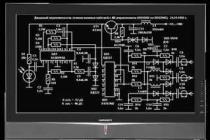
Tell me, how to determine where which element is located on the board, otherwise I cannot understand ... I'm just not experienced yet ...
The figure above the diagram shows the assembly here on it and determine where to put which element
▼ Show all comments ▼
There are two 4700µF 50V capacitors on the assembly line, and there are other elements, what are they for? Don't kick me for such stupid questions, it's just that I don't know much about electronics ...
if you double the number of transistors in the output stage, is it possible to increase the power? Or let's replace them with kt825 and kt827?
Hi all. As I understand it, the total supply voltage is unipolar from the unit comes 70 volts, is divided by the conductors and it turns out 35v each?
no. Conders cannot share food. the transformer must have two secondary units with a common wire, i.e. the transformer has 3 wires on the secondary. the voltage of each shoulder from the midpoint should be 24 (25) volts alternating. after the diode bridge and capacitors, the voltage increases 1.4 times (you will just get 35 volts per shoulder. see bipolar power supply circuits.
thanks to dr.Alex. I want to make such a car .. but this circuit with a converter will work? http://goo.gl/aqlfZ there is an amp and a converter. I just did this and I still have these rings in stock ... how many turns and how to wind, tell me pliz ... preferably with a wire of 1 mm ...
thanks to dr.Alex. and 35v 200v will be enough for this amp?
in the sense of 35 volts for a 200 watt amplifier? in principle, you will definitely get 160-170 watts (although 200 is also possible). provided that the transformer has a capacity of 200-250 watts, it is designed for a secondary current of 4 amperes. (cross-section of the secondary wire 1-1.4 mm) power supply capacitors on the shoulder at least 30,000 microfarads.
as practice shows, a house has enough power of 30-70 watts per channel. for a car, 100 watts for the eyes is enough. these are examples for comfortable listening.
Guys and 45 volts in one shoulder, will he be okay?
Can you change the weekend for KT837 and KT805? If so, how much power will fall ???
text
Considering the maximum power dissipation of the pair you have chosen, 30W watts 20 with a wheeze, you will pull out from there. You can take non-metal versions of KT818-819, they are more affordable and cheaper, and with radiators it is easier to get them.
I'll tell you, I made this amplifier, but I put domestic ones instead of imported parts and it works for me made 2 channels on the output put kt818g kt819g and he quietly, without any problems, rocks the s90 speakers, though I got it done, but it was worth it !!! without a preamplifier, it won't even swing on the pallet! before I put the amplifier from the TV on un14 somewhere about 120 watts it gives me !!!
The alternating voltage at the output at a maximum volume of 30V is somewhere around 120W !!!
Is the output capacitor worn out ??? And then I burned a bunch of speakers, I don't want to burn the C-90))
who made this device can tell which of the cheap and affordable transyuk it is desirable to have a bourgeois tip to make an atom into a magician went and asked how much the price would be and the desire dropped :)))
Classic 2SC5200 / 2SA1943 not an option? One hundred square meters can be met.
Ahh .. well people well answer the question! Does the given ULF need an output capacitor ??? And then I am racking my head as if to not burn something! Who started it at all ???
No, it doesn't. But the input is desirable. About 1 microfarad.
Thank you kind person !!!
although it is written that for the sub, but I will take an interest from those who collected it how this amp transmits bass, okay? I just plan to shove it into the sub)))) I think to put 2SC5200 / 2SA1943 on the weekends. Q4 and Q5 are there exactly bc557 and bc546, do not burn out? here I read that without a preliminary amplifier, it does not swing for all this is true
This amplifier is still playing me on Soviet transistors !!!
For Chron:… in order not to burn anything “for sure”, you need to take 2 e-mail. Conder, connect them in series. The resulting 3-pole is connected with the "plus" to the "plus" of the power supply; “Minus” - to the “minus” of the IP, and to the “middle” point the 2nd wire from the speaker (instead of “ground”) .Thus, the speaker will never fail (it is the most expensive part), since at the junction of the "encoders" there will never be a "constant", and according to the "change" - always ZERO. Please note! The maximum voltage of the electric encoder must be 2 times higher than the voltage of the 1 ″ arm ”of the power supply, as well as their ratings must be the same.
Isn't it an option to test and adjust an amplifier with an equivalent load and only then connect the speakers and listen? :)
I assembled an amplifier according to this scheme, transistors were installed by our KT827A and KT819VM, I connect it, from the speaker, and how it sticks, what could be the problem, who can tell?
Replace KT819VM with KT825 or the KT827A transistor for KT818VM, since KT827A and KT819VM are not complementary, i.e. mutually complementary, it is advisable to use them like this, approximately KT818VM and KT819VM or KT825 and KT827. Because KT827 is a composite and KT819VM is not.
I am a bit "noob" in this business, and therefore there are a couple of questions:
print the topology of the board as it is shown or in a mirror image;
a low-pass filter must be installed;
an 8 ohm speaker will work? thanks
Has anyone collected from kt825 and kt827 at the output? Or 2sc5200 and 2sa1943? Does the circuit work?
Is the line-out level (0.7V) not enough for full drive?
and what power resistors to take all except R7 and R8?
does not work. I'm crooked
Check printed circuit board Are the tracks intact and are there no short circuits between them where there should not be, whether the resistors are in accordance with the circuit, capacitors, transistors are correctly soldered and for serviceability, whether the power supply is correct, if it would be desirable to have a photo of your amplifier and what exactly does not work, otherwise it is so difficult to suggest that or, and the circuit is 100% working, I did all the details on the circuit, only the output transistors KT818GM and KT819GM at the output managed to get a maximum of 17V at a load of 4 Ohms, and the amplifier's power supply was 35V in the shoulder.
I soldered this circuit. I used TIP 142 and TIP 147 at the output stage. It started working right away, it sounds fine. But how do you know how many watts it produces? Everywhere they write that it is possible to accurately measure only with the help of a generator and an oscilloscope. Output during operation with a 4 ohm subwoofer AC voltage fluctuates (multimeter needle) up to 25 volts. The current at the input of the converter is an average of 9 amperes (at a voltage of 11.7 V)
But how do you know how many watts it produces?
I have assembled this amplifier. I want to say he plays very well (he rocked my sub for 75gdn without any problems). I feed it with a voltage of 37v in the shoulder. Instead of bc546 he put kt3102, instead of bc557-kt3107, 2n3055-kt819gm, MJ2955-kt818gm. Plays fine without any preamps directly from the computer. If you have it when you connect the input to something, it will fart or pop, put a 2.2-10 microfarad condenser and a 22-47kf resistor in front of the input, it helped me. I also fed him with a 27c strap on the shoulder and also played normally, but 2 times quieter. The R6 rezyuk heats up not weakly, so put a rezyuk with a power of half cotton wool (it is easiest to get a 2.4-ohm milliliter for half cotton wool). I wish you the best of luck in assembling this amp).
Collected, turn on, there is a small background in the dynamics and KT818 heats up to the utmost. To the reaction signal 0. I collected it on KT819GM and KT818GM. what's up ?!
Yura leave your contacts we will solve the problem! I already know this amplifier by heart