Sine wave signal generator with frequency from 1 Hz to 40 MHz with adjustable output level and built-in output signal level meter (Up/p), as well as a sweeper mode (SFS) with arbitrary selection of boundaries in the range from 1 Hz to 40 MHz


I offer kits for assembling a generator (GEN) of sinusoidal signals 1 Hz - 40 MHz with a sweep frequency generator (GKCH / WOB), an additional sawtooth voltage output for oscilloscope synchronization, as well as a 0/5 V square wave output with a sweep frequency generator. This device developed by the Polish radio amateur Adam Sobczyk (SQ5RWQ). This design was published in the magazine ELEKTRONIKA PRAKTYCZNA.
The device is assembled using a ready-made DDS module of the AD9850 synthesizer, which greatly simplifies installation. Moreover, both commercially available DDS AD9850 modules can be used. Structurally, the device consists of two printed circuit boards - the main and the controller. The main board has connectors for the controller board, connectors for synthesizer modules (only one synthesizer board can be used at a time), contact pins for external connections, a screw terminal block for power supply, +5V and +9V voltage stabilizers are assembled, as well as a broadband RF signal amplifier . The controller board has a two-line LCD display, an encoder for selecting operating modes and settings, and a variable resistor for adjusting the output signal level.
The choice of the operating mode GEN - generator or WOB - Wobbulator / GKCH is selected when the device is turned on by pressing and holding the encoder button. When the welcome menu appears, you need to press the encoder button and wait for the menu to appear in which you need to select the GEN or WOB mode by rotating the encoder and then confirm the choice by pressing the encoder button. In the next menu, the operating mode of the 0-5 V square-wave digital output is selected in the same way, i.e. Turning the encoder selects the ON or OFF mode and pressing the encoder button confirms the selection. The selected modes will be stored in the non-volatile memory during subsequent power-ups. To select another mode of operation, you need to de-energize the device and reapply voltage, enter the menu for selecting operating modes and select the desired mode. In generator mode, the tuning step is changed in a circle by pressing the encoder button. In the GKCh mode, pressing the encoder button selects the active menu item - opposite the active (which can be changed at the moment) parameter, an asterisk "*" is lit at the moment. As the encoder is rotated, the value of the selected parameter will change. Switching between the parameters to be changed occurs in a circle. The device is in oscillation mode when there is no asterisk on the screen, i.e. all options are selected.

The circuit diagram of the control/indication board is shown below, as well as

The circuit diagram of the main board is shown below and also

The device operates in two modes:
1) Generator of sinusoidal signals with a frequency of 1 Hz - 40 MHz
2) Sweep frequency generator with sinusoidal signal sweep range from 1 Hz - 40 MHz.
In the first mode, the display shows the frequency of the output signal with an accuracy of 1 Hz, the selected frequency tuning step (selected by pressing the button built into the encoder, i.e. by pressing the encoder knob) and the output voltage level in Volts from peak to peak - Up / p. The tuning step is selected in a circle from a frequency grid of 1 Hz, 10 Hz, 100 Hz, 1 kHz, 10 kHz, 100 kHz, 1 MHz by pressing the encoder button. The output voltage level almost coincides with the oscilloscope readings, the output signal frequency corresponds exactly. The output signal level decreases with increasing frequency, this is due to the peculiarity of the operation of the AD9850 itself. On the low frequencies the output voltage for various DDS modules is in the order of 4 volts and drops to 1 volt at 40 MHz. More precisely, with a pure sine wave at the output, I got it like this:
40 MHz - Up/p=0.89 V
35 MHz - Up/p=1.18 V
30 MHz - Up/p=1.67 V
25 MHz - Up/p=2.09 V
20 MHz - Up/p=2.38 V
15 MHz - Up/p=2.62 V
10 MHz - Up/p=2.99 V
5 MHz - Up/p=3.37 V
1 MHz - Up/p=3.66 V
Then, practically unchanged up to 30 Hz and then with a smooth decrease to Up / p = 2.08 V at a frequency of 5 Hz and up to Up / p = 0.86 V at a frequency of 1 Hz.
In the second mode, the display shows the oscillation frequency, the frequency tuning step, the lower and upper limits of the generator frequency oscillation. The choice and change of parameters is carried out by the encoder by analogy with the first mode of operation - by pressing and rotating the encoder knob. The oscillation frequency is selected from 1 Hz to 40 MHz in 1 Hz steps, the tuning step in a circle from the frequency grid is 1 Hz, 10 Hz, 100 Hz, 1 kHz, 10 kHz, 100 kHz, 1 MHz, the upper and lower oscillation frequencies are from 1 Hz up to 40 MHz, while the upper limit is set first, and then the lower one, since there is a software limitation - the lower frequency is always less than or equal to the upper one.
A properly assembled device from serviceable parts :) starts working immediately. Before installing the indication/controller board and the AD9850 module, apply power to the main board and check for +9 V and +5 V supply voltages after the 7809 and 7805 regulators respectively. Then check the voltage levels at the outputs of the broadband power amplifier transistors. The voltages should be as follows: Q1 (collector - 6.65 V; emitter - 1.4 V; base - 2.1 V), Q2 (emitter - 7.37 V; collector - 2.5 V), Q3 (collector - 5.47 V; emitter - 1.74 V). If necessary, use the trimming resistor on the board of the AD9850 module to set the duty cycle of the rectangular pulses at the output of the generator to 2 (duty factor 0.5), i.e. meander.
The boards are designed to be installed in a standard KM-60 plastic case, but ideally, of course, use a metal case :)
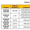
The cost of printed circuit boards and assembly kits are as follows:
The cost of a set of two printed circuit boards (main 140x90 mm and indication 115x45 mm) with a mask and marking is 300 UAH.
If someone needs a separately programmed microcontroller - 85 UAH.
The cost of the generator assembly kit (programmed microcontroller with a socket, printed circuit boards and all components for them, including racks, screws, washers, nuts, heatsinks, encoder, variable resistor, knobs, LCD display 16x2) excluding AD9850 module- 830 UAH
Cost of assembled and tested generator boards (main and controller/indication board) excluding AD9850 module- 1200 UAH
Frequency generator-synthesizer module AD9850 - 650 UAH. (I put in the kit the one that is available, if the type is important, then specify in advance, I have differences in the operation of the boards different types did not see). This oscillator is based on the AD9850 chip from Analog Devices, which is a complete DDS (Direct Digital Synthesis) frequency synthesizer with a built-in comparator. Such synthesizers are unique in their accuracy, are practically not subject to temperature drift and aging.
A small "glitch" was found, most likely a software one - it slows down the encoder during rotation. It doesn't bother me, but it's better to get rid of it. I think everything will be resolved :) The advantages of the device overlap its disadvantages :) I have been looking for a lot, but I have not found such a simple and adequate device ...
Below are several circuits of low-frequency oscillators using low-frequency quartz, for frequencies such as 100 kHz, 36 kHz, 32.768 kHz. You can use quartz for other frequencies. A circuit of a micropower generator at 135 kHz is also presented. All circuits were assembled as a result of experiments with a signal repeater 500 kHz - 144 MHz.
135 kHz generator

A feature of the synthesizer is the use of a ceramic quartz resonator at 455 kHz, a digital divider by 10 and an analog multiplier by 3. This generator is a micropower device with a current consumption of 1.5 mA at a supply voltage of 5 Volts. The output voltage level can be significant, the output is high-resistance. The master oscillator is tuned over a wide range - from 448 to 457 kHz or more with a slight deterioration in frequency stability, but it is still more than that of an LC oscillator. The resulting frequency will be from 134.4 to 137.1 kHz, which is convenient for use as a master oscillator in a LW transmitter. On transistor VT1 the master oscillator was assembled according to the capacitive three-point scheme. Chip IC1 - included according to the divisor circuit by 10. On VT2 a multiplier by 3 is assembled. The collector circuit is used as a load on L1 tuned to nominal frequency. The circuit is wound in an armored core from the erasure-bias generator of an old tape recorder and contains 50 turns of stranded litz wire (the number of turns is selected based on the existing core). Increasing the value of C5 decreasing R4 can significantly increase the voltage on the circuit L1C7C8C9. View more link . Source - Radio magazine No. 6 1990 (Frequency synthesizer on the 144 MHz band).
100 kHz generator

The classic circuit of a quartz oscillator with a capacitive three-point. When using a high-quality quartz resonator in a glass bulb, it is operable in wide changes in the supply voltage. from 1.5 volts or less to 12 volts. The value of the resistor R 2 is from 1 kOhm to 30 kOhm. With a nominal value of 30 kOhm, the current consumption from a 1.5 V element is 40 μA. C1, C2 - changes in the generation frequency. C1 may be missing. With watch quartz in small-sized cylindrical cases, the circuit does not work
36 kHz generator (1 option)

This oscillator uses the LM386 low-frequency power amplifier. This is not a typical switching circuit for this microcircuit, however, the circuit works stably with low-frequency quartz resonators. Operable when changing supply voltages from 5 to 12 volts. C1 - frequency adjustment. At low voltages, the circuit is not operational.
36 kHz generator (option 2)

The circuit is based on the use of a low-frequency amplifier with feedback on C2 and a quartz resonator between the base and collector of 2 transistors. The circuit is operable in wide variations of the supply voltage. from 1.5 volts or less to 12 volts. In the circuit, you can change the values of any elements within a wide range without violating the circuit's performance. C2 - adjustment of the generation frequency. The frequency, consumption currents and output power. Transistors are interchangeable with KT342.
PS:
Perhaps the schemes described here in amateur radio creativity will be useful to you!
Low-frequency generators (LFGs) are used to obtain undamped periodic oscillations of electric current in the frequency range from fractions of a Hz to tens of kHz. Such generators, as a rule, are amplifiers covered by positive feedback (Fig. 11.7,11.8) through phase-shifting chains. To implement this connection and to excite the generator, the following conditions are necessary: the signal from the output of the amplifier must be fed to the input with a phase shift of 360 degrees (or a multiple of it, i.e. 0, 720, 1080, etc. degrees), and itself the amplifier must have some gain margin, KycMIN. Since the condition for the optimal phase shift for the occurrence of generation can be satisfied only at one frequency, it is at this frequency that the amplifier with positive feedback is excited.

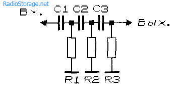
To shift the signal in phase, RC and LC circuits are used, in addition, the amplifier itself introduces a phase shift into the signal. To obtain positive feedback in the generators (Fig. 11.1, 11.7, 11.9), a double T-shaped RC bridge was used; in generators (Fig. 11.2, 11.8, 11.10) - Wien's bridge; in generators (Fig. 11.3 - 11.6, 11.11 - 11.15) - phase-shifting RC chains. In generators with RC chains, the number of links can be quite large. In practice, to simplify the scheme, the number does not exceed two or three.


Calculation formulas and ratios for determining the main characteristics of RC-generators of sinusoidal signals are given in Table 11.1. For ease of calculation and simplification of the selection of parts, elements with the same ratings were used. To calculate the generation frequency (in Hz), the values of resistance expressed in Ohms are substituted into the formulas, and capacitances - in Farads. For example, let's determine the generation frequency of an RC oscillator using a three-link RC positive feedback circuit (Fig. 11.5). At R \u003d 8.2 kOhm; C \u003d 5100 pF (5.1x1SG9 F) the operating frequency of the generator will be equal to 9326 Hz.
Table 11.1

In order for the ratio of the resistive-capacitive elements of the generators to correspond to the calculated values, it is highly desirable that the input and output circuits of the amplifier covered by the positive feedback loop do not shunt these elements and do not affect their value. In this regard, to build generator circuits, it is advisable to use amplification stages with high input and low output resistance.
On fig. 11.7, 11.9 shows the "theoretical" and simple practical schemes of generators using a double T-bridge in a positive feedback circuit.
Wien bridge generators are shown in fig. 11.8, 11.10 [R 1/88-34]. A two-stage amplifier was used as a ULF. The amplitude of the output signal can be adjusted with potentiometer R6. If you want to create a generator with a Wien bridge, tunable in frequency, in series with resistors R1, R2 (Fig. 11.2, 11.8) include a dual potentiometer. The frequency of such a generator can also be controlled by replacing the capacitors C1 and C2 (Fig. 11.2, 11.8) with a double variable capacitor. Insofar as maximum capacity of such a capacitor rarely exceeds 500 pF, it is possible to tune the generation frequency only in the region of sufficiently high frequencies (tens, hundreds of kHz). The generation frequency stability in this range is low.


In practice, to change the generation frequency of such devices, switched sets of capacitors or resistors are often used, and field-effect transistors are used in the input circuits. In all the above circuits, there are no elements for stabilizing the output voltage (for simplicity), although for generators operating at the same frequency or in a narrow range of its tuning, their use is not necessary.
Sinusoidal signal generator circuits using three-link phase-shifting RC chains (Fig. 11.3)


shown in fig. 11.11, 11.12. The generator (Fig. 11.11) operates at a frequency of 400 Hz [R 4/80-43]. Each of the elements of a three-link phase-shifting RC chain introduces a phase shift of 60 degrees, with a four-link - 45 degrees. A single-stage amplifier (Fig. 11.12), made according to the scheme with a common emitter, introduces a phase shift of 180 degrees necessary for the generation to occur. Note that the generator according to the circuit in Fig. 11.12 is operable when using a transistor with a high current transfer ratio (usually over 45 ... 60). With a significant decrease in the supply voltage and a non-optimal choice of elements for setting the transistor mode according to direct current generation will fail.


Sound generators (Fig. 11.13 - 11.15) are similar in construction to generators with phase-shifting RC chains [Рl 10/96-27]. However, due to the use of inductance (telephone capsule TK-67 or TM-2V) instead of one of the resistive elements of the phase-shifting chain, they work with a smaller number of elements and in a larger range of supply voltage changes.


So, the sound generator (Fig. 11.13) is operational when the supply voltage changes within 1 ... 15 V (current consumption 2 ... 60 mA). In this case, the generation frequency changes from 1 kHz (upit = 1.5 V) to 1.3 kHz at 15 V.
Sound indicator with external management(fig. 11.14) also works at 1) supply=1...15 V; the generator is turned on / off by applying logic levels of one / zero to its input, which should also be within 1 ... 15 V.
The sound generator can also be made according to another scheme (Fig. 11.15). The frequency of its generation varies from 740 Hz (consumption current 1.2 mA, supply voltage 1.5 V) to 3.3 kHz (6.2 mA and 15 V). The generation frequency is more stable when the supply voltage changes within 3 ... 11 V - it is 1.7 kHz ± 1%. In fact, this generator is no longer made on RC, but on LC elements, moreover, the winding of a telephone capsule is used as an inductance.
The low-frequency generator of sinusoidal oscillations (Fig. 11.16) is assembled according to the "capacitive three-point" scheme characteristic of LC generators. The difference lies in the fact that the coil of a telephone capsule is used as an inductance, and the resonant frequency is in the range of sound vibrations due to the selection of capacitive circuit elements.


Another low-frequency LC-oscillator, made according to the cascode scheme, is shown in Fig. 11.17 [R 1/88-51]. As an inductance, you can use a universal or erasing heads from tape recorders, windings of chokes or transformers.
The RC generator (Fig. 11.18) is implemented on field-effect transistors [Рl 10/96-27]. A similar scheme is usually used in the construction of highly stable LC oscillators. Generation already occurs at a supply voltage exceeding 1 V. When the voltage changes from 2 to 10 6, the generation frequency decreases from 1.1 kHz to 660 Hz, and the current consumption increases, respectively, from 4 to 11 mA. Pulses with a frequency from units of Hz to 70 kHz and higher can be obtained by changing the capacitance of the capacitor C1 (from 150 pF to 10 μF) and the resistance of the resistor R2.

The sound generators presented above can be used as economical status indicators (on/off) of components and blocks of radio electronic equipment, in particular, light emitting diodes, for replacing or duplicating light indication, for emergency and alarm indication, etc.
Literature: Shustov M.A. Practical Circuitry (Book 1), 2003
Low frequencies are designed to receive periodic low-frequency electrical signals at the output of the device with given parameters(shape, amplitude, signal frequency).
KR1446UD1 (fig. 35.1) is a double nut-to-rail OU general purpose. Based on this microcircuit, devices for various purposes can be created, in particular, electrical oscillations, which are shown in Fig. 35.2-35.4. (Fig. 35.2):
♦ simultaneously and synchronously generates rectangular and sawtooth voltage pulses;
♦ has a single artificial middle point for both op amps, formed by the voltage divider R1 and R2 .
Built on the first of the op-amps, on the second - Schmitt with a wide hysteresis loop (U raCT \u003d U nHT; R3 / R5), accurate and stable switching thresholds. The generation frequency is determined by the formula:
f =———– and amounts to 265 Gi for the denominations indicated on the diagram. With
Rice. 35.7. Pinout and composition of the microcircuit KR 7446UD7

Rice. 35.2. generator of rectangular-triangular pulses on the chip KR1446UD 7
by changing the supply voltage from 2.5 to 7 V, this frequency changes by no more than 1%.
The improved one (Fig. 35.3) generates rectangular pulses, and their frequency depends on the value of the control

Rice. 35.3. controlled square wave generator
input voltage according to the law
![]() When it changes
When it changes
input voltage from 0.1 to 3 V, the generation frequency increases linearly from 0.2 to 6 kHz.
The generation frequency of the rectangular pulse generator on the KR1446UD5 microcircuit (Fig. 35.4) is linear in the value of the applied control voltage and at R6 = R7 is determined as:

5 V generation frequency increases linearly from 0 to 3700 Hz.

Rice. 35.4. voltage controlled generator
So, when the input voltage changes from 0.1 to
Based on TDA7233D chips, using as single basis basic element, fig. 35.5, a, you can collect sufficiently powerful pulses (), as well as voltages, fig. 35.5.
The generator (Fig. 35.5, 6, top) operates at a frequency of 1 kHz, which is determined by the selection of the elements Rl, R2, Cl, C2. The capacitance of the transition capacitor C sets the timbre and volume of the signal.
The generator (Fig. 35.5, b, bottom), produces a two-tone signal, subject to the individual selection of the capacitance of the capacitor C1 in each of the basic elements used, for example, 1000 and 1500 pF.
Voltages (Fig. 35.5, c) operate at a frequency of about 13 kHz (capacitor C1 is reduced to 100 pF):
♦ upper - generates negative gel voltage relative to the common bus;
♦ medium - produces a positive doubled relative to the supply voltage;
♦ lower - generates, depending on the transformation ratio, a bipolar equal voltage with galvanic (if necessary) isolation from the power source.

Rice. 35.5. abnormal use of TDA7233D microcircuits: a - basic element; b - as pulse generators; c - as voltage converters
When assembling converters, it should be taken into account that a significant part of the output voltage is lost on the rectifier diodes. In this regard, it is recommended to use Schottky as VD1, VD2. The load current of transformerless converters can reach 100-150 mA.
Rectangular pulses (Fig. 35.6) operate in the frequency range 60-600 Hz \ 0.06-6 kHz; 0.6-60 kHz. To correct the shape of the generated signals, a chain can be used (lower part of Fig. 35.6), connected to points A and B of the device.
Having covered the op-amp with positive feedback, it is easy to transfer the device to the mode of generating rectangular pulses (Fig. 35.7).
Variable frequency pulses (Fig. 35.8) can be made on the basis of the DA1 chip. When used as DA1 1/4 of the LM339 microcircuit, by adjusting the potentiometer R3, the operating frequency is tuned within 740-2700 Hz (the value of the capacitance C1 is not indicated in the original source). The initial generation frequency is determined by the product C1R6.

Rice. 35.8. wide-range tunable oscillator based on comparator

Rice. 35.7. generator of rectangular pulses at a frequency of 200 Hz

Rice. 35.6. LF square-wave generator
On the basis of comparators such as LM139, LM193 and the like, the following can be assembled:
♦ rectangular pulses with quartz stabilization (Fig. 35.9);
♦ pulses with electronic tuning.
Frequency-stable oscillations or the so-called “hourly” rectangular pulses can be performed on the DAI LTC1441 comparator (or similar) according to the typical circuit shown in fig. 35.10. The generation frequency is set by a quartz resonator Z1 and is 32768 Hz. When using a line of frequency dividers by 2, rectangular pulses with a frequency of 1 Hz are obtained at the output of the dividers. Within a small range operating frequency generator can be lowered by connecting in parallel with a resonator of small capacity.
Typically, LC and RC- are used in electronic devices. Less known are LR-, although devices with inductive sensors can be created on their basis,

Rice. 35.11. LR generator

Rice. 35.9. pulse generator on the comparator LM 7 93

Rice. 35.10. "clock" pulse generator
Detectors for wiring, pulses, etc.
On fig. 35.11 shows a simple LR square-wave generator operating in the frequency range 100 Hz - 10 kHz. As inductance and for sound
the generator operation is controlled by a telephone capsule TK-67. Frequency tuning is carried out by potentiometer R3.
Operable when the supply voltage changes from 3 to 12.6 V. When the supply voltage drops from 6 to 3-2.5 V, the upper generation frequency rises from 10-11 kHz to 30-60 kHz.
Note.
The range of generated frequencies can be extended to 7-1.3 MHz (for a microcircuit) by replacing the telephone capsule and resistor R5 with an inductor. In this case, when the diode limiter is turned off, signals close to a sinusoid can be obtained at the output of the device. The stability of the generation frequency of the device is comparable to the stability of RC generators.
Sound signals (Fig. 35.12) can be performed K538UNZ. To do this, it is enough to connect the input and output of the microcircuit with a capacitor or its analogue - a piezoceramic capsule. In the latter case, the capsule also acts as a sound emitter.
The generation frequency can be changed by selecting the capacitance of the capacitor. In parallel or in series, a piezoceramic capsule can be switched on to select the optimal generation frequency. The supply voltage of the generators is 6-9 V.

Rice. 35.72. audio frequencies on a chip
For an express check of the op-amp, a generator can be used sound signals shown in fig. 35.13. The tested DA1 chip of type , or others with a similar pinout, is inserted into the socket, after which the power is turned on. If it is in good condition, the HA1 piezoceramic capsule emits a sound signal.

Rice. 35.13. sound generator - OS tester

Rice. 35.14. generator of rectangular pulses on OUKR1438UN2

Rice. 35.15. generator of sinusoidal signals on OUKR1438UN2
Rectangular signals at a frequency of 1 kHz, made on the KR1438UN2 chip, are shown in fig. 35.14. amplitude-stabilized sinusoidal signals at a frequency of 1 kHz is shown in fig. 35.15.
The generator that generates sinusoidal signals is shown in fig. 35.16. This one operates in the 1600-5800 Hz frequency range, although at frequencies above 3 kHz, the waveform is increasingly far from ideal, and the output signal amplitude drops by 40%. With a tenfold increase in the capacitances of capacitors C1 and C2, the tuning band of the generator, while maintaining the sinusoidal waveform, decreases to 170-640 Hz with an amplitude unevenness of up to 10%.

Rice. 35.7 7. generator of sinusoidal oscillations at a frequency of 400 Hz
This low-frequency harmonic sinusoidal signal generator circuit is designed for tuning and repairing audio frequency amplifiers.
Sine Wave Generator together with a millivoltmeter, an oscilloscope or a distortion meter, it creates a valuable complex for tuning and repairing all stages of an audio frequency amplifier.
Main characteristics:
- Generated frequencies: 300Hz, 1kHz, 3kHz.
- Maximum Harmonic Distortion (THD): 0.11% - 1kHz, 0.23% - 300Hz, 0.05% - 3kHz
- Current consumption: 4.5 mA
- Output voltage selection: 0 - 77.5 mV, 0 - 0.775 V.
The sinusoidal generator circuit is quite simple and is built on two transistors, which provide high frequency and amplitude stability. The oscillator design does not require any stabilization elements such as tubes, thermistors, or other special amplitude limiting components.
Each of the three frequencies (300 Hz, 1 kHz and 3 kHz) is set by switch S1. The amplitude of the output signal can be smoothly changed by means of a variable resistor R15 in two ranges, which are set by switch S2. Available amplitude ranges: 0 - 77.5 mV (219.7 mV pk-pk) and 0 - 0.775 V (2.191 V pk-pk).
 The following figures show the wiring printed circuit board and the arrangement of elements on it.


List of required radio components:
- R1-12k
- R2-2k2
- R3, R4, R5, R15 - 1k variable
- R6, R7 - 1K5
- R8-1k
- R9-4k7
- R10-3k3
- R11-2k7
- R12-300
- R13-100k
- C1 - 22n
- C2 - 3u3
- C3 - 330n
- C4 - 56n
- C5 - 330n
- C6, C7 - 100n
- D1, D2 - 1N4148
- T1, T2, T3 - BC337
- IO1-78L05
If all parts are installed correctly and there are no errors in the installation, the sinusoidal signal generator should work the first time it is turned on.
The supply voltage of the circuit can be in the range of 8-15 volts. To maintain a stable amplitude of the output signal voltage, the power line is additionally stabilized by the 78L05 microcircuit and diodes D1, D2, as a result, the output of the stabilizer is about 6.2 volts.
Before turning on for the first time, you must connect the generator output to a frequency meter or oscilloscope and use trimmer resistors R3, R4 and R5 to set the exact output frequency for each of the ranges: 300 Hz, 1 kHz and 3 kHz. If necessary, if it is not entirely possible to adjust the frequencies, then you can additionally select the resistance of constant resistors R6-R8.
http://pandatron.cz/?1134&sinusovy_generator_s_nizkym_zkreslenim