This is a fairly common question that has several solutions. There is one of the most popular ways to solve the problem, regulation occurs through an active ballast connection at the output of the winding (secondary).
On the territory of the Russian Federation, welding for alternating current consists in the used frequency of 50 Hz. A 220V network is used as a power source. And all transformers for welding have a primary and secondary winding.
In units used in an industrial area, the current regulation is carried out in different ways. For example, using the moving functions of the windings, as well as magnetic shunting, various types of choke shunting. Ballast resistance stores (active) and a rheostat are also used.
Such a choice of welding current strength cannot be called a convenient way, due to the complex design scheme, overheating and discomfort during switching.
A more convenient way to regulate the welding current is if you wind the secondary (secondary winding) by making taps, which will allow you to change the voltage when switching the number of turns.
But controlling the voltage within wide limits, in this case, will not work. Also note certain disadvantages when adjusting from the secondary circuit.
Thus, the regulator of the welding current, at the initial speed, passes a high frequency current (HFC) through itself, which entails the bulkiness of the structure. And standard switches of the secondary circuit do not imply a load of 200 A. But in the primary winding circuit, the indicators are 5 times less.
As a result, an optimal and convenient tool was found, in which the adjustment of the welding current does not seem so confusing - this is a thyristor. Experts always note its simplicity, ease of use and high reliability. The strength of the welding current depends on the disconnection of the primary winding for specific periods of time, at each of the voltage half-periods. At the same time, the average voltage indicators will decrease.
The principle of thyristor operation
The parts of the regulator are connected both in parallel and opposite to each other. They are gradually opened by current pulses, which are formed by the vt2 and vt1 transistors. When the device is started, both thyristors are closed, C1 and C2 are capacitors, they will be charged through the r7 resistor.
At that moment, as the voltage of any of the capacitors reaches the voltage of the avalanche breakdown of the transistor, it opens, and the discharge current flows through it, which is shared with the capacitor. After opening the transistor, the corresponding thyristor opens, it will connect the load to the network. Then the opposite half-cycle of the alternating voltage begins, which involves the closure of the thyristor, then a new cycle of charging the capacitor follows, already in the opposite polarity. Next, the next transistor opens, but again connects the load to the network.
DC and AC welding
In the modern world, DC welding is used to a greater extent. This is due to the possibility of reducing the amount of electrode filler material in the weld. But when welding with alternating voltage, a very high quality welding result can be achieved. Welding power sources operating with alternating voltage can be divided into several types:
- Devices for argon arc welding. It uses special electrodes that do not melt, thanks to which argon welding becomes as comfortable as possible;
- Apparatus for the production of RDS with alternating electric current;
- Semi-automatic welding equipment.
Variable welding methods are divided into two types:
- the use of non-consumable electrodes;
- stick electrodes.
There are two types of DC welding, reverse polarity and direct polarity. In the second version, the welding current moves from minus to positive, and the heat is concentrated on the workpiece. And the opposite one focuses on the end of the electrode.
The DC welding generator consists of a motor and a current generator itself. They are used for manual welding in assembly work and in the field.
Making a regulator
To make a control device for the welding current, you will need the following components:
- Resistors;
- Wire (nichrome);
- Coil;
- project or device diagram;
- Switch;
- Steel spring;
- Cable.
Ballast joint operation
The ballast resistance indicator of the regulating apparatus is at the level of 0.001 Ohm. He is selected by experiment. Directly to obtain resistance, the resistance of high-power wires is mainly used; they are used in trolleybuses or on lifts.
It is possible to reduce the high frequency welding voltage even by using a steel door spring.
Such resistance is switched on permanently or in another way, so that in the future it will be possible to easily adjust the indicators. One edge of this resistance is connected to the output of the transformer structure, the other is provided with a special clamping tool that can be thrown along the entire length of the spiral, which will allow you to select the desired voltage strength.
The main part of the resistors using high power wire is produced in the form of an open coil. It is mounted on a structure half a meter long. Thus, the spiral is also made from the wire of the heating element. When resistors made of a magnetic alloy cooperate with a spiral or any part of steel, during the operation of the passage of high current, it will begin to tremble noticeably. The spiral possesses such dependence only until it stretches.
How to make a choke yourself?
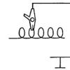
It is quite real to make an independent choke at home. This is the case when there is a straight coil with enough turns of the desired cord. Straight metal plates from the transformer are held inside the coil. By choosing the thickness of these plates, it is possible to select the starting reactance.
Let's look at a specific example. Choke with a coil with 400 turns and a cord with a diameter of 1.5 mm, filled with plates with a cross section of 4.5 square centimeters. The length of the coil and wire must be the same. As a result, the transformer current of 120 A will be halved. Such a choke is manufactured with a resistance that can be changed. To carry out such an operation, it is necessary to measure the recess in the passage of the core rod into the coil. Without this tool, the coil will have little resistance, but if the rod is inserted into it, the resistance will increase to a maximum.
A choke that is wound with the correct cord will not overheat, but there may be strong vibration in the core. This is taken into account when tying and fastening iron plates.
One of the main components of truly high quality is the correct and precise setting of the welding current in accordance with the task at hand. Experienced welders often have to work with metal of different thicknesses, and sometimes the standard min / max adjustment is not enough for full-fledged work. In such cases, there is a need for multi-stage current regulation, with an accuracy of ampere. This problem can be easily solved by including an additional device in the circuit - a current regulator.
The current can be regulated in the secondary (secondary winding) and in the primary (primary winding). Moreover, each of the methods for setting up a transformer for welding has its own characteristics, which are important to consider. In this article, we will tell you how the current is adjusted in, we will give the diagrams of regulators for the welding, we will help you to choose the correct welding current regulator for the primary winding for the welding transformer.
There are many ways to adjust the current, and above we wrote about the secondary and primary windings. In fact, this is a very rough classification, since the regulation is still divided into several components. We will not be able to make out all the components within the framework of this article, so we will focus on the most popular ones.
One of the most commonly used current regulation methods is the addition of a secondary winding at the output. This is a reliable and durable way, the ballast can be easily made with your own hands and used in work without additional devices. Often, ball players are used exclusively to reduce the current strength.

If you are not ready to put up with these disadvantages, we recommend that you pay attention to the method when the welding current is adjusted in the primary winding. For these purposes, electronic devices are often used, which can be easily made by hand. Such a device will smoothly regulate the primary current and will not cause inconvenience to the welder during operation.
The electronic regulator will become an indispensable assistant to the summer resident, who is forced to carry out welding in conditions of unstable voltage. Often houses are simply not supposed to use electrical appliances of more than 3-5 kW, and this is very limiting in their work. With the help of the regulator, you can configure your device so that it can operate smoothly even with low voltage. Also, such a device is useful for craftsmen who need to constantly move from place to place during work. After all, the regulator does not need to be dragged along like a ball player, and it will never cause injury.
Now we will talk about how to make an electronic regulator yourself from thyristors.
Thyristor regulator circuit
![]()
Above you can see the diagram of the simplest regulator on 2 thyristors with minimums of non-scarce parts. You can also make a regulator based on a triac, but our practice has shown that a thyristor power regulator is more durable and works more stable. The circuit for assembly is very simple and you can use it to assemble the regulator pretty quickly with minimal soldering skills.
The operating principle of this regulator is also simple. We have a primary circuit, into which the regulator is connected. The regulator consists of transistors VS1 and VS2 (for each half-wave). The RC circuit determines the moment when the thyristors open, at the same time the resistance R7 changes. As a result, we get the opportunity to change the current in the primary of the transformer, after which the current changes in the secondary.
Note! The regulator is tuned under voltage, this should not be forgotten. To avoid fatal errors and not get injured, it is imperative to isolate all radioelements.
In principle, you can use old-style transistors. This is a great way to save money, since such transistors can easily be found in an old radio or at a flea market. But keep in mind that such transistors must be used at an operating voltage of at least 400 V. If you see fit, you can put dinistors instead of the transistors and resistors shown in the diagram. We did not use dinistors, because in this version they do not work very stably. In general, this thyristor-based welding current regulator circuit has proven itself well and on its basis many regulators have been manufactured that work stably and perform their function well.
You could also see the RKS-801 regulator and the RKS-15-1 contact welding regulator in stores. We do not recommend making them yourself, as it will take a lot of time and will not save you much money, but if you wish, you can make RKS-801. Below you see a diagram of the regulator and a diagram of its connection to the welder. Open pictures in a new window to see the text better.
Measurement of welding current
After you have made and configured the regulator, you can use it in work. To do this, you need another device that will measure the welding current. Unfortunately, it will not be possible to use household ammeters, since they are not capable of working with a power of more than 200 amperes. Therefore, we recommend using a clamp meter. It is a relatively inexpensive and accurate way to find out the current value, and the operation of the clamp is clear and simple.
The so-called "clamps" at the top of the instrument grip the wire and measure the current. On the body of the device there is a switch for the limits of current measurement. Depending on the model and price, different manufacturers make clamp meters that can operate in the range from 100 to 500 amperes. Select a device that matches yours.
A clamp meter is an excellent choice if you need to quickly measure the current value without affecting the circuit or connecting additional elements to it. But there is one drawback: the clamp is absolutely useless when measuring the value. The fact is that direct current does not create an alternating electromagnetic field, so the device simply does not see it. But in working with such a device meets all expectations.
There is another way to measure current, it is more radical. You can add an industrial ammeter capable of measuring high currents to the circuit of your semiautomatic welding machine. You can also just temporarily add an ammeter to the open circuit of the welding wires. On the left you can see a diagram of such an ammeter, according to which you can assemble it.
This is a cheap and effective way to measure current, but the use of an ammeter in welding machines also has its own peculiarities. Not the ammeter itself is added to the circuit, but its resistor or shunt, while the dial indicator must be connected in parallel to a resistor or shunt. If you do not follow this sequence, the device will simply not work at best.
Instead of a conclusion
Adjusting the welding current on a semiautomatic device is not as difficult as it might seem at first glance. If you have minimal knowledge in the field of electrical engineering, you can easily assemble a current regulator for a welding machine on trimistors on your own, saving on buying this device in a store. Homemade regulators are especially important for DIYers who are not prepared for the extra hardware costs. Tell us about your experience in making and using the current regulator in the comments and share this article on your social networks. We wish you good luck with your work!


A fairly large number of industrial electric drives and technological processes use direct current for their power supply. Moreover, in such cases, it is quite often necessary to change the value of this voltage. Such types of transport as the subway, trolleybuses, electric cars and other types of transport receive their supply voltage from DC networks with constant voltage. But after all, many of them need to change the value of the voltage supplied to the armature of the electric motor. The classical means of obtaining the required values are resistive control, or the Leonardo system. But these systems are outdated and rarely seen (especially the generator-engine system). More modern and actively introduced systems are thyristor converter-motor, pulse converter motor. Let's consider each system in more detail.
Resistor regulation
To regulate the starting current and voltage supplied to the electric motor, resistors are connected to the armature circuit in series with the armature (or the armature and the excitation winding in the case of a series excitation motor):
Thus, the current supplied to the electric machine is regulated. Contactors K1, K2, K3 bypass the resistors when it is necessary to change any parameter or coordinates of the drive. This method is still quite widespread, especially in traction electric drives, although it is accompanied by large losses in resistors and, as a consequence, a rather low efficiency.
Generator-engine system
In such a system, the required voltage level is formed by changing the excitation flux of the generator:

The presence of three electric machines in such a system, large weight and size indicators and a long repair time in case of breakdowns, as well as expensive maintenance and high inertia of such an installation made the efficiency of such a machine very low. Now there are practically no generator-engine systems left, all of them are being actively replaced by systems that have a number of advantages.
Thyristor converter - motor
Received its massive development in the 60s, when thyristors began to appear. It was on their basis that the first static low-power thyristor converters were created. Such devices were connected directly to AC mains:

Voltage regulation occurs by changing. Regulation through a thyristor converter has a number of advantages over the generator-motor installation, such as high speed and efficiency, smooth DC voltage regulation and many others.
DC link converter
Things are a little more complicated here. To obtain a constant voltage of the required value, auxiliary devices are also used, namely, an inverter, a transformer, a rectifier:

Here, direct current is converted into alternating current using a current inverter, then using a transformer, it is reduced or increased (depending on the need), and then rectified again. The presence of a transformer and an inverter significantly increases the cost of the installation, enlarges the system, which reduces the efficiency. But there is also a plus - galvanic isolation between the network and the load due to the presence of a transformer. In practice, such devices are extremely rare.
Switching DC voltage converters
These are perhaps the most modern control devices in DC circuits. It can be compared to a transformer, since the behavior of a pulse converter is similar to a transformer with a smoothly varying number of turns:

Such systems are actively replacing electric drives with resistive control by connecting them to the armature of the machine in series, instead of a resistive-contactor group. I use them quite often in electric cars, and they have also become quite popular in underground transport (subway). Such converters emit a minimum of heat, which does not heat up the tunnels and can implement a regenerative braking mode, which is a big plus for electric drives with frequent starting and braking.
The big advantage of such devices is that they can recuperate energy into the network, smoothly regulate the rate of current rise, have high efficiency and speed.
Recently I came across an interesting circuit diagram of a simple but pretty good entry-level power supply unit capable of delivering 0-24 V at a current of up to 5 amperes on the Internet. The power supply provides protection, that is, limiting the maximum current during overload. In the attached archive there is a printed circuit board and a document that describes the settings for this block, and a link to the author's website. Please read the description carefully before assembling.

Here is a photo of my version of the power supply unit, a view of the finished board, and you can see how to roughly apply a case from an old computer ATX. The adjustment is made 0-20 V 1.5 A. Capacitor C4 for such a current is set to 100 μF 35 V.

In the event of a short circuit, a maximum limited current is issued and the LED lights up, brought the limiter resistor to the front panel.
Power supply indicator
I conducted an audit at my place, found a couple of simple M68501 arrow heads for this power supply unit. I spent half a day creating a screen for him, but I still drew it and fine-tuned it to the required output voltages.

The resistance of the indicator head used and the resistor used are indicated in the attached file on the indicator. I spread the front panel of the unit, if anyone needs a case from the ATX power supply for remaking, it will be easier to rearrange the inscriptions and add something than to create from scratch. If other voltages are required, the scale can simply be calibrated, this will be easier. Here is the finished view of the regulated power supply:

The film is a self-adhesive "bamboo" type. The indicator has a green backlight. Red LED Attention indicates that overload protection is activated.

Add-ons from BFG5000
The maximum limiting current can be made more than 10 A. On a cooler - a 12 volt roll plus a temperature regulator of revolutions - from 40 degrees it starts to increase revolutions. The circuit error does not particularly affect the operation, but judging by the measurements with a short circuit, an increase in the passing power appears.

The power transistor was installed 2n3055, everything else is also foreign counterparts, except for BC548 - supplied by KT3102. The result is a really unkillable PSU. For novice radio amateurs, that's just the right thing.

The output capacitor is set at 100 uF, the voltage does not jump, the adjustment is smooth and without visible delays. I set it from the calculation as indicated by the author: 100 microfarads of capacity per 1 A of current. Authors: Igoran and BFG5000.
Discuss the article POWER SUPPLY UNIT WITH CURRENT AND VOLTAGE REGULATION
There are various ways to adjust the welding current, but it can be said that the most widespread among the people is a very simple and reliable way of adjusting the current - using the ballast resistance included at the output of the secondary winding. The method is not only simple and reliable, but also useful, as it improves the external characteristics of the transformer, increasing the steepness of its fall. In some cases, ballast resistances are used purely to correct the rigid characteristics of the welding machine.
The value of the ballast resistance for the welding current regulator is of the order of hundredths to tenths of an Ohm and is selected, as a rule, experimentally. For a long time, powerful wire resistances used in cranes, trolleybuses, or sections of spirals of heating elements (heat and electric heaters), pieces of thick high-resistance wire have been used as ballast resistance. The current can be somewhat reduced even with a stretched steel door spring. The ballast resistance can be switched on either permanently.
Or so that then it was possible to relatively easily adjust the welding current. One end of such a resistance is connected to the output of the transformer, and the end of the welding wire is equipped with a removable clamp, which can be easily thrown along the length of the resistance spiral, choosing the required current.


Nichrome wire as ballast resistance (4 mm in diameter and 8 m in length). The wire can be of a smaller diameter, and thus a shorter length will be needed, but it will heat up more.

Most wire-wound resistors of high power are made in the form of an open spiral, installed on a ceramic frame up to half a meter long, as a rule, the wire from the heating elements is wound into a spiral. If the resistor is made of magnetic alloys, then in the case of its spiral arrangement, and even more so with any steel structural elements inside the spiral, when high currents pass, the spiral begins to vibrate strongly. After all, the spiral is the same solenoid, and huge welding currents generate powerful magnetic fields. You can reduce the effect of vibrations by stretching the spiral and fixing it on a rigid base. In addition to the spiral, the wire can also be bent with a snake, which also reduces the size of the finished resistor. The cross-section of the conductive material of the resistor should be selected more, because it gets very hot during operation. Too thin wire or tape will glow red-hot, although even this, in principle, does not exclude the effectiveness of using it as a current regulator for a welding machine. It is difficult to judge the real value of the resistance of wire-wound ballast resistors, since in a heated state the properties of materials change greatly.
In industrial welding machines, the method of adjusting the current by switching on active resistances, due to their bulkiness and heating, has not become widespread. But reactance is very widely used - the inclusion of a choke in the secondary circuit. Chokes have a variety of designs, often combined with the magnetic circuit of the transformer in one piece, but made in such a way that their inductance, and hence the reactance, is regulated mainly by moving parts of the magnetic circuit. At the same time, the throttle improves the arc burning process.
The regulation of the current in the secondary circuit of a welding transformer is associated with certain problems. Significant currents pass through the regulating device, which leads to its bulkiness. Another inconvenience is switching. For the secondary circuit, it is almost impossible to select such powerful standard switches that they can withstand currents up to 200A. Another thing is the primary winding circuit, where the currents are about five times less, the switches for which are consumer goods. In series with the primary winding, as in the previous case, ballast resistors can be included. Only in this case, the resistance of the resistors should be an order of magnitude greater than in the secondary winding circuit. So, a battery of several parallel-connected resistors PEV-50 ... 100 with a total resistance of 6-8 Ohm is able to reduce the output current by half, or even three times, depending on the design of the transformer. You can collect multiple batteries and install a switch. If you do not have a powerful switch at your disposal, then you can get by with several switches. By installing resistors according to the scheme shown below, you can, for example, make a welding current regulator with a combination: 0; 4; 6; 10 ohm.


True, when the ballast resistance is turned on in the primary circuit, the benefit that the resistance gives in the secondary circuit is lost - an improvement in the falling characteristics of the transformer. But on the other hand, the resistors switched on by high voltage do not lead to any negative consequences in the burning of the arc: if the transformer cooked well without them, then it will cook with additional resistance in the primary winding.
In idle mode, the transformer consumes a small current, which means that its winding has significant resistance. Therefore, an additional few ohms have little or no effect on the idle output voltage.
Instead of resistors, which will get very hot during operation, a reactance - a choke - can be installed in the primary winding circuit.

This measure should be seen rather as a way out if no other means of reducing the power is available. The inclusion of reactance in the high voltage circuit can greatly reduce the open circuit output voltage of the transformer. A drop in the output voltage is observed in transformers with a relatively high no-load current - 2-3A. With an insignificant current consumption - about 0.1A - the drop in the output voltage is almost imperceptible. In addition, included in the primary winding of the transformer, the choke can lead to some deterioration in the welding characteristics of the transformer, although not so much that it cannot be used. In the latter case, it is still highly dependent on the properties of the particular transformer. For some welding machines, the inclusion of a choke in the primary circuit of the transformer does not affect, at least according to subjective feelings, the quality of arc burning.
As a choke of the welding machine, to adjust the current, you can use a ready-made secondary winding of some transformer, designed for an output of about 40V and a power of 200-300 W, then you will not have to redo anything. Although it is still better to make a homemade choke by winding a wire on a separate frame from the same transformer - 200-300 W, for example from a TV, making taps every 30-60 turns connected to a switch.

A homemade choke can also be made on an open - straight core. This is convenient when you already have a ready-made coil with several hundred turns of a suitable wire. Then inside it you need to stuff a package of straight plates of transformer iron. The required reactance is set by selecting the thickness of the package, guided by the welding current of the transformer. For example: a choke made of a coil, presumably containing about 400 turns of wire with a diameter of 1.4 mm, was packed with a bag of iron with a total cross section of 4.5 cm 2, a length equal to the length of the coil, 14 cm.This made it possible to reduce the welding current of the 120A transformer. about twice. An inductor of this type can also be made with an adjustable reactance. For this, the depth of insertion of the core rod into the coil cavity can be changed. The coreless coil has a low resistance, with the rod fully inserted, its resistance is maximum. The choke, wound with a suitable wire, heats up a little, but its core vibrates strongly. This must be taken into account when tightening and fixing a set of iron plates.
For homemade welding machines, it is easiest, even when winding the windings, to make them with taps and, by switching the number of turns, change the current. However, this method can be used only for adjusting the current, rather than for adjusting it over a wide range. Indeed, in order to reduce the current by 2-3 times, it will be necessary to increase the number of turns of the primary winding too much, which will inevitably lead to a voltage drop in the secondary circuit. Or you will have to increase the turns of all coils, which will lead to excessive wire consumption, an increase in the size and weight of the transformer.
For a finer adjustment of the welding current to the lower side, you can use the inductance of the welding cable by laying it in rings. But do not overdo it, because the cable will heat up.
Recently, thyristor and triac schemes for adjusting the welding current have become somewhat widespread. When a voltage of a certain value is applied to the control output of a thyristor or triac, the regulator opens and begins to freely pass current through itself. In AC current control circuits, control pulses are usually supplied every half cycle. The regulator opens at strictly defined (set) times, thus cutting off the beginning of each half-cycle of the current sinusoid, which reduces the total power of the passing electrical signal.

Naturally, the current and voltage after that do not have a sinusoidal shape. Such circuits allow you to adjust the power over a wide range. A person who is versed in radio electronics will be able to make such a circuit on his own, although, I must say, devices of this kind cannot be considered perfect. When using regulators of this type, the arc burning process deteriorates somewhat. Indeed, now, with a decrease in power, the arc begins to burn in separate, more and more short-lived flashes. For most of the circuits of thyristor regulators, the scales are not linear, and the calibration changes with a change in the mains voltage, the current through the thyristor gradually increases during operation due to heating of the circuit elements. In addition, the output power is usually noticeably damped even at the maximum opening position of the regulator, to which welding transformers are very sensitive. This method of adjusting the welding current, due to the complexity of manufacture and low reliability, is not widely used among home-made welding current regulators.
Measurement of welding current
To measure high currents, in this case up to 200A, devices are required that have their own specifics and are not widely used in everyday life. One of the simpler solutions is to use a clamp meter.
The specificity of measurement with this device is that it does not need to be connected to an electrical circuit for measurement. The current is measured at a distance from the wire without touching it. The device has a special dividing circuit, which is why the name - "pincers", which covers the wire with current. The electromagnetic field of the current flowing in the covered wire induces a current in a closed loop, which is measured. On the body of the "clamp" there is a switch for the limits of current measurement, the maximum values of which usually reach - from 100A to 500A for different models of devices. The clamp meter can be used quickly in almost any situation without affecting the electrical circuit. They can measure only alternating current, which creates an alternating electromagnetic field; for direct current, this instrument is useless. The accuracy class in this case is very low, so it is possible to judge, rather, only about approximate values.
Another way to measure the welding current is to mount an ammeter designed for high current values into the electrical circuit of a welding machine being manufactured or an industrial machine being modified, or even just turn it on for a while in a break in the welding wire circuit.
The inclusion of an ammeter in the welding circuit is also noted with some specificity. The fact is that not the device itself (pointer pointer), but its shunt (resistor) is connected in series into the circuit, while the pointer indicator is connected to the shunt in parallel.

The shunt has its own resistance: presumably hundredths of Ohm (since it cannot be measured with an ordinary ohmmeter). It looks like a piece of metal a few centimeters in length with a rectangular cross-section with powerful contact pads on both sides. The accuracy of the meter reading also depends on the accuracy of the shunt resistance. A shunt of a specific resistance is provided for each ammeter model and must be sold together.

And what in no case needs to be done is to try to include the dial gauge in the circuit without a shunt at all. If you have somewhere lying around a dial gauge, on the scale of which hundreds of amperes appear, this does not mean at all that he measures them himself. Check it out: the device itself will turn out to be just a micro- or milliammeter. Sometimes you come across dial gauges with a shunt mounted inside the case and you don't need to connect anything else to it. As a rule, such are distinguished by their huge dimensions and low accuracy class.
Of no small importance is the ability of the pointer of the measuring device to be set to the current value, overcoming oscillatory transient processes when the current changes, otherwise the arrow will frantically dance along the scale even with minor changes in current, which are inevitable when the welding arc is burning.
When using the content of this site, you need to put active links to this site, visible to users and search robots.