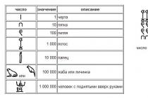
In order to correctly read and understand what a particular diagram or drawing related to electricity means, you need to know how the icons and symbols depicted on them are deciphered. A large amount of information contains letter designations elements in electrical diagrams defined by various regulatory documents. All of them are displayed in Latin characters in the form of one or two letters.
One-letter symbolism of elements
Letter codes corresponding to individual types of elements most widely used in electrical circuits are combined into groups designated by one symbol. Letter designations correspond to GOST 2.710-81. For example, the letter "A" refers to the "Devices" group, which consists of lasers, amplifiers, telecontrol devices and others.
In the same way, the group denoted by the symbol "B" is deciphered. It consists of devices that convert non-electrical quantities into electrical ones, which do not include generators and power supplies. This group is complemented by analog or multi-digit converters as well as indicating or measuring sensors. The components themselves included in the group are microphones, loudspeakers, pickups, detectors of ionizing radiation, thermoelectric sensing elements, etc.
All letter designations corresponding to the most common elements are combined in a special table for ease of use:
|
The first alphabetic character required for reflection in the marking |
Group of basic types of elements and devices |
Elements that make up the group (the most typical examples) |
|
|
Devices |
Lasers, masers, telecontrol devices, amplifiers. |
||
|
Apparatus for converting non-electrical quantities into electrical (without generators and power supplies), analog and multi-charge converters, sensors for indications or measurements |
Microphones, loudspeakers, pickups, ionizing radiation detectors, sensitive thermoelectric elements. |
||
|
Capacitors |
|||
|
Micro assemblies, integrated circuits |
Digital and analog integrated circuits, memory and delay devices, logic elements. |
||
|
Miscellaneous elements |
Various types of lighting devices and heating elements. |
||
|
Fuse designation on the diagram, arresters, protective devices |
Fuses, arresters, discrete current and voltage protection elements. |
||
|
Power supplies, generators, quartz oscillators |
Rechargeable batteries, power supplies on an electrochemical and electrothermal basis. |
||
|
Devices for signals and indications |
Indicators, light and sound signal izations |
||
|
Contactors, relays, starters |
Voltage and current relays, time relays, electric thermal relays, magnetic starters, contactors. |
||
|
Chokes, inductors |
Chokes in fluorescent lighting. |
||
|
Engines |
DC and AC motors. |
||
|
Measuring instruments and equipment |
Counters, clocks showing, registering and measuring instruments. |
||
|
Power circuit breakers, short-circuits, disconnectors. |
|||
|
Resistors |
|||
|
Pulse counters |
|||
|
Frequency meters |
|||
|
Active energy meters |
|||
|
Reactive energy meters |
|||
|
Recording devices |
|||
|
Action time meters, hours |
|||
|
Voltmeters |
|||
|
Wattmeters |
|||
|
Switches and disconnectors in power circuits |
Circuit breakers |
||
|
Short-circuits |
|||
|
Disconnectors |
|||
|
Resistors |
Thermistors |
||
|
Potentiometers |
|||
|
Measuring shunts |
|||
|
Varistors |
|||
|
Switching devices in measurement, control and signaling circuits |
Switches and switches |
||
|
Push-button switches |
|||
|
Automatic switches |
|||
|
Switches triggered by various factors: From level |
|||
|
From pressure |
|||
|
From position (travel) |
|||
|
From rotation frequency |
|||
|
From temperature |
|||
|
Transformers, autotransformers |
Current transformers |
||
|
Electromagnetic stabilizers |
|||
|
Voltage transformers |
|||
|
Communication devices, converters of non-electrical quantities into electrical |
Modulators |
||
|
Demodulators |
|||
|
Discriminators |
|||
|
Frequency generators, inverters, frequency converters |
|||
|
Semiconductor and vacuum devices |
Diodes, Zener Diodes |
||
|
Electrovacuum devices |
|||
|
Transistors |
|||
|
Thyristors |
|||
|
Antennas, microwave lines and elements |
Taps |
||
|
Short-circuits |
|||
|
Transformers, phase shifters |
|||
|
Attenuators |
|||
|
Contact connections |
Sliding contacts, current collectors |
||
|
Dismountable connections |
|||
|
High frequency connectors |
|||
|
Mechanical devices with electromagnetic drive |
Electromagnets |
||
|
Electromagnetic brakes |
|||
|
Electromagnetic clutches |
|||
|
Electromagnetic holders or plates |
|||
|
Limiters, terminal devices, filters |
Limiters |
||
|
Quartz filters |
In addition, GOST 2.710-81 defines Special symbols to designate each item.
Conditional graphic symbols of electronic components in circuits
Graphic designation of radio components on the diagrams. Designation of radio components on the diagram and their name
| Designation | Name | Photo | Description |
| Earthing | Protective grounding - protects people from electric shock in electrical installations. | ||
| A battery is a galvanic cell in which chemical energy is converted into electrical energy. | |||
| A solar cell is used to convert solar energy into electrical energy. | |||
| Voltmeter - a measuring device for determining the voltage or EMF in electrical circuits. | |||
| Ammeter - a device for measuring current strength, the scale is calibrated in microamperes or in amperes. | |||
| Switch - a switching device designed to turn on and off individual circuits or electrical equipment. | |||
| The tact button is a switching mechanism that closes the electrical circuit while there is pressure on the pusher. | |||
| Incandescent lamps general purpose, designed for indoor and outdoor lighting. | |||
| Motor (motor) - a device that converts electrical energy into mechanical work (rotation). | |||
| Piezodynamics (piezo emitters) are used in technology to notify an incident or event. | |||
| A resistor is a passive element of electrical circuits with a certain value of electrical resistance. | |||
| The variable resistor is designed for smooth change current, by changing its own resistance. | |||
| Photoresistor | A photoresistor is a resistor whose electrical resistance changes under the influence of light rays (lighting). | ||
| Thermistor | Thermistors or thermistors are semiconductor resistors with a negative temperature coefficient of resistance. | ||
| Fuse - an electrical device designed to disconnect the protected circuit by destruction. | |||
| The capacitor serves to store the charge and energy of the electric field. The capacitor charges and discharges quickly. | |||
| The diode has different conductivity. The purpose of a diode is to conduct electric current in one direction. | |||
| A light-emitting diode (LED) is a semiconductor device that creates optical radiation when electricity is transmitted. | |||
| A photodiode is a receiver of optical radiation that converts light into electric charge due to the process in the p-n-junction. | |||
| A thyristor is a semiconductor switch, i.e. a device whose purpose is to close and open a circuit. | |||
| The purpose of the zener diode is to stabilize the voltage across the load, with a changing voltage in the external circuit. | |||
| A transistor is a semiconductor device designed to amplify and control an electric current. | |||
| A phototransistor is a semiconductor transistor that is sensitive to the luminous flux (illumination) that irradiates it. |
xn - 18-6kcdusowgbt1a4b.xn - p1ai
For Beginners About Radio Parts | Master Cog. Do it yourself!
In order to assemble the circuit, what kind of radio components are not needed: resistors (resistances), transistors, diodes, capacitors, etc. From the variety of radio components, one must be able to quickly distinguish what is needed in appearance, decipher the inscription on its body, and determine the pinout. All this will be discussed below.
This detail is practically found in every scheme of amateur radio designs. As a rule, the simplest capacitor is two metal plates (plates) and air between them as a dielectric. Instead of air, there can be porcelain, mica, or other non-conductive material. Direct current does not pass through the capacitor, but the alternating current passes through the capacitor. Due to this property, the capacitor is placed where it is necessary to separate the direct current from the alternating current.
For a capacitor, the main parameter is capacity.
The unit of capacity - microfarad (μF) is taken as a basis in radio amateur designs and in industrial equipment. But more often another unit is used - picofarad (pF), a millionth fraction of a microfarad (1 microfarad = 1,000 nf = 1,000,000 pf). In the diagrams, you will find both the one and the other unit. Moreover, capacities up to 9100 pF inclusive are indicated on the diagrams in picofarads or nanofarads (9n1), and above - in microfarads. If, for example, next to the condenser symbol is written "27", "510" or "6800", then the capacitance of the capacitor is respectively 27, 510, 6800 pF or n510 (0.51 nF = 510 pF or 6n8 = 6.8 nF = 6800pf). But the numbers 0.015, 0.25 or 1.0 indicate that the capacitance of the capacitor is the corresponding number of microfarads (0.015 microfarads = 15 nf = 15,000 pf).
Types of capacitors.
Capacitors are of constant and variable capacitance.
In variable capacitors, the capacitance changes when the axis protruding outward is rotated. In this case, one pad (movable) finds it not movable without touching it, as a result, the capacity increases. In addition to these two types, our designs use another type of capacitor - a trimmer. Usually it is installed in one or another device in order to more accurately select the required capacitance and not touch the capacitor anymore. In amateur designs, a trimmer capacitor is often used as a variable capacitor - it is cheaper and more affordable.

Capacitors differ in the material between the plates and in the design. There are air, mica, ceramic, etc. capacitors. This type of permanent capacitors is not polar. Another type of capacitor is electrolytic (polar). Such capacitors produce large capacity- from a tenth of a microfarad to several tens of microfarads. On the diagrams for them, not only the capacity is indicated, but also the maximum voltage at which they can be used. For example, the inscription 10.0 x 25 V means that a 10 μF capacitor must be taken at a voltage of 25 V.
For variable or trimming capacitors, the diagram indicates the extreme values of the capacitance, which are obtained if the capacitor axis is rotated from one extreme position to another or rotated round and round (like in trimming capacitors). For example, the inscription 10 - 240 indicates that in one extreme position of the axis the capacitance of the capacitor is 10 pF, and in the other - 240 pF. With a smooth rotation from one position to another, the capacitance of the capacitor will also smoothly change from 10 to 240 pF or vice versa - from 240 to 10 pF.
I must say that this part, like the capacitor, can be seen in many homemade products. It is a porcelain tube (or rod), on which the thinnest film of metal or soot (carbon) is sprayed on the outside. A nichrome thread is wound on top of low-resistance high-power resistors. A resistor has a resistance and is used to set the desired current in an electrical circuit. Consider the example of a reservoir: by changing the diameter of the pipe (load resistance), you can get one or another water flow rate (electric current of different strength). The thinner the film on the porcelain tube or rod, the greater the resistance to current.
Resistors are constant and variable.
Of the constants, the most commonly used resistors are MLT (metallized varnished heat-resistant), VS (moisture-resistant resistance), ULM (small-sized carbon varnished), from variables - SP (variable resistance) and SPO (variable volumetric resistance). The appearance of fixed resistors is shown in Fig. below.

Resistors are distinguished by resistance and power. Resistance, as you already know, is measured in ohms (ohms), kilohms (kohms) and megohms (megohms). Power is expressed in watts and this unit is denoted by the letters W. Resistors of different power differ in size. The higher the power of the resistor, the larger its size.
The resistance of the resistor is marked on the diagrams next to its symbol. If the resistance is less than 1 kOhm, the numbers indicate the number of ohms without a unit of measurement. With a resistance of 1 kΩ or more - up to 1 MΩ, indicate the number of kilo-ohms and put the letter "k" next to it. Resistance of 1 megohm and above is expressed by the number of megohms with the addition of the letter "M". For example, if on the diagram next to the resistor designation it is written 510, then the resistance of the resistor is 510 Ohm. The designations 3.6 k and 820 k correspond to resistances of 3.6 kΩ and 820 kΩ, respectively. The inscription on the diagram 1 M or 4.7 M means that resistances of 1 MΩ and 4.7 MΩ are used.
Unlike fixed resistors having two terminals, variable resistors have three such terminals. The diagram indicates the resistance between the extreme terminals of the variable resistor. The resistance between the middle terminal and the extreme ones changes when the outward protruding axis of the resistor is rotated. Moreover, when the axis is turned in one direction, the resistance between the middle terminal and one of the extreme increases, respectively, decreasing between the middle terminal and the other extreme. When the axis is turned back, the opposite occurs. This property of a variable resistor is used, for example, to control the volume of sound in amplifiers, receivers, televisions, etc.
Semiconductor devices.
They are made up of a whole group of parts: diodes, zener diodes, transistors. Each part uses a semiconductor material, or more simply a semiconductor. What it is? All existing substances can be roughly divided into three large groups. Some of them - copper, iron, aluminum and other metals - conduct electric current well - these are conductors. Wood, porcelain, plastic do not conduct electricity at all. They are non-conductors, insulators (dielectrics). Semiconductors occupy an intermediate position between conductors and dielectrics. Such materials conduct current only under certain conditions.
A diode (see figure below) has two leads: an anode and a cathode. If you connect a battery to them with poles: plus - to the anode, minus - to the cathode, a current will flow in the direction from the anode to the cathode. The resistance of the diode in this direction is small. If you try to change the poles of the batteries, that is, turn on the diode "vice versa", then the current will not flow through the diode. In this direction, the diode has a high resistance. If we pass an alternating current through the diode, then at the output we will receive only one half-wave - it will be, though pulsating, but direct current. If an alternating current is applied to four diodes connected by a bridge, then we will already get two positive half-waves.

These semiconductor devices also have two leads: the anode and the cathode. In the forward direction (from the anode to the cathode), the zener diode works like a diode, passing current unhindered. But in the opposite direction, at first, it does not pass current (like a diode), and with an increase in the voltage supplied to it, it suddenly "breaks through" and begins to pass current. The "breakdown" voltage is called the stabilization voltage. It will remain unchanged even with a significant increase in the input voltage. Due to this property, the zener diode is used in all cases when it is necessary to obtain a stable supply voltage of some device during fluctuations, for example, the mains voltage.

Of the semiconductor devices, the transistor (see figure below) is most often used in electronics. It has three outputs: base (b), emitter (e) and collector (k). A transistor is an amplifying device. It can be conditionally compared with such a device known to you as a horn. It is enough to say something in front of the narrow opening of the horn, directing the wide one towards a friend standing several tens of meters away, and the voice amplified by the horn will be clearly heard in the distance. If we take a narrow hole as the input of a horn-amplifier, and a wide one as an output, then we can say that the output signal is several times larger than the input. This is the indicator of the amplifying ability of the speaker, its amplification factor.

Now the variety of manufactured radio components is very rich, therefore, not all of their types are shown in the figures.
But back to the transistor. If a weak current is passed through the base-emitter section, it will be amplified by the transistor tens and even hundreds of times. The amplified current will flow through the collector-emitter section. If the transistor is ringing the base-emitter and base-collector with a multimeter, then it is similar to measuring two diodes. Depending on the highest current that can be passed through the collector, transistors are divided into low-power, medium and high-power. In addition, these semiconductor devices can be pnp or npp structures. This is how transistors differ with different alternation of layers of semiconductor materials (if there are two layers of material in a diode, there are three of them). The gain of a transistor is independent of its structure.
Literature: B. S. Ivanov, "ELECTRONIC DIY"

P O P U L R N O E:
>>
SHARE WITH FRIENDS:
Popularity: 29,094 views.
www.mastervintik.ru
RADIO ELEMENTS
This reference material provides the appearance, name and marking of the main foreign radio components - microcircuits different types, connectors, quartz resonators, inductors and so on. The information is really useful, since many are well acquainted with domestic parts, but not very much with imported ones, and after all, they are the ones that are installed in all modern schemes. Minimum knowledge of English is encouraged, since all the inscriptions are not in Russian. For convenience, the parts are grouped together. Do not pay attention to the first letter in the description, for example: f_Fuse_5_20Glass - means a 5x20 mm glass fuse.


As for the designation of all the indicated radioelements on electrical circuit diagrams - see reference information on this issue in another article.
Parts Forum
Discuss the article RADIO ELEMENTS
radioskot.ru
| AM | amplitude modulation |
| AFC | automatic frequency control |
| APCHG | automatic local oscillator frequency control |
| APCHF | automatic frequency and phase control |
| AGC | automatic gain control |
| ARYA | automatic brightness control |
| AS | acoustic system |
| AFU | antenna feeder device |
| ADC | analog-to-digital converter |
| Frequency response | frequency response |
| BGIMS | large hybrid integrated circuit |
| NOS | wireless remote control |
| BIS | large integrated circuit |
| Biofeedback | signal processing unit |
| BP | power unit |
| BR | scanner |
| DBK | radio channel unit |
| BS | mixing block |
| BTK | blocking transformer personnel |
| BTS | blocking transformer lowercase |
| BOO | Control block |
| BC | color block |
| BCI | integrated chromaticity unit (using microcircuits) |
| VD | video detector |
| VIM | pulse time modulation |
| WU | video amplifier; input (output) device |
| HF | high frequency |
| G | heterodyne |
| GW | reproducing head |
| MHF | high frequency generator |
| MHF | hyperhigh frequency |
| GZ | start generator; recording head |
| GIR | heterodyne resonance indicator |
| GIS | hybrid integrated circuit |
| GKR | frame generator |
| GKCH | sweeping frequency generator |
| GMV | meter wave generator |
| GPA | smooth range generator |
| GO | envelope generator |
| HS | signal generator |
| GSR | line generator |
| gss | standard signal generator |
| yy | clock generator |
| GU | universal head |
| GUN | voltage controlled generator |
| D | detector |
| dv | long waves |
| dd | fractional detector |
| day | voltage divider |
| dm | power divider |
| dmv | decimeter waves |
| DU | remote control |
| DShPF | dynamic noise reduction filter |
| EASC | unified automated communication network |
| ESKD | unified system of design documentation |
| hr | sound frequency generator; master oscillator |
| ss | decelerating system; sound signal; pickup |
| ZCH | sound frequency |
| AND | integrator |
| iqm | pulse code modulation |
| IKU | quasi-peak meter |
| ims | integrated circuit |
| ini | linear distortion meter |
| inch | infra-low frequency |
| and he | reference voltage source |
| sp | power supply |
| ichh | frequency response meter |
| To | switch |
| KBV | traveling wave ratio |
| Kv | short waves |
| kvh | extremely high frequency |
| kzv | recording-playback channel |
| Kim | pulse code modulation |
| kk | frame reel deflector |
| km | coding matrix |
| knch | extremely low frequency |
| efficiency | efficiency |
| KS | coil deflection line |
| csv | standing wave ratio |
| ksvn | voltage standing wave ratio |
| CT scan | check Point |
| CF | focusing coil |
| TWT | traveling wave lamp |
| lz | delay line |
| fishing | backward wave lamp |
| lpd | avalanche diode |
| lppt | lamp-semiconductor TV |
| m | modulator |
| MA | magnetic antenna |
| MB | meter waves |
| mdp | metal-dielectric-semiconductor structure |
| MNP | metal-oxide-semiconductor structure |
| ms | chip |
| MU | microphone amplifier |
| nor | nonlinear distortion |
| LF | low frequency |
| ABOUT | common base(switching on the transistor according to the scheme with a common base) |
| sheepskin | very high frequency |
| oi | common source (turning on the transistor * according to the scheme with a common source) |
| OK | common collector (switching on the transistor according to the scheme with a common collector) |
| onch | very low frequency |
| oos | negative feedback |
| OS | deflection system |
| OU | operational amplifier |
| OE | common emitter (switching on the transistor according to the scheme with a common emitter) |
| Surfactant | surface acoustic waves |
| pds | dual-voice prefix |
| Remote control | remote control |
| pkn | code-voltage converter |
| pnc | voltage-to-code converter |
| pnch | converter voltage frequency |
| pos | positive feedback |
| PPU | jamming device |
| pch | intermediate frequency; frequency converter |
| ptk | tv channel switch |
| pts | full tv signal |
| Vocational school | industrial television set |
| PU | preliminary effort |
| PUV | playback preamplifier |
| BLS | recording preamplifier |
| PF | band pass filter; piezofilter |
| nx | transfer characteristic |
| pcts | full color television signal |
| Radar | line linearity regulator; radar station |
| RP | memory register |
| Rhcg | manual adjustment of the local oscillator frequency |
| RRS | row size adjuster |
| PC | shift register; mixing regulator |
| RF | notch or block filter |
| CEA | electronic equipment |
| SBDU | wireless remote control system |
| VLSI | ultra-large-scale integrated circuit |
| SV | medium waves |
| swp | touch program selection |
| Microwave | ultra high frequency |
| cr | signal generator |
| SDV | extra-long waves |
| SDU | dynamic light installation; remote control system |
| SC | channel selector |
| SLE | all-wave channel selector |
| sk-d | UHF channel selector |
| SK-M | meter wave channel selector |
| CM | mixer |
| ench | ultra-low frequency |
| Joint venture | mesh field signal |
| ss | sync signal |
| ssi | horizontal sync pulse |
| SU | selector amplifier |
| nt | average frequency |
| Tv | tropospheric radio waves; TV |
| tvs | output transformer line |
| tvz | audio output channel transformer |
| tvk | output transformer |
| Titus | TV test chart |
| TKE | temperature coefficient of capacitance |
| weaves | temperature coefficient of inductance |
| tkmmp | temperature coefficient of initial permeability |
| tcns | temperature coefficient of stabilization voltage |
| tks | temperature coefficient of resistance |
| mf | network transformer |
| mall | television center |
| ttsp | color stripe table |
| THAT | technical conditions |
| Have | amplifier |
| HC | playback amplifier |
| UVS | video amplifier |
| UVH | fetch-store device |
| UHF | high frequency signal amplifier |
| UHF | UHF |
| UZ | recording amplifier |
| UZCH | audio amplifier |
| VHF | ultrashort waves |
| ULPT | unified semiconductor tube TV |
| ULLCT | unified tube semiconductor color TV |
| ULT | unified tube TV |
| UMZCH | audio power amplifier |
| CNT | unified tv |
| ULF | low frequency amplifier |
| UNU | voltage controlled amplifier. |
| UTP | constant current amplifier; unified semiconductor TV |
| UCH | intermediate frequency amplifier |
| UPCHZ | intermediate frequency amplifier sound? |
| UPCHI | image intermediate frequency amplifier |
| URCH | radio frequency amplifier |
| US | interface device; comparison device |
| UHCH | microwave amplifier |
| OSS | horizontal sync amplifier |
| USU | universal touch device |
| Uu | control device (node) |
| UE | accelerating (control) electrode |
| UEIT | universal electronic test chart |
| PLL | phase locked loop |
| HPF | high pass filter |
| FD | phase detector; photodiode |
| FIM | phase-pulse modulation |
| FM | phase modulation |
| LPF | low pass filter |
| FPF | intermediate frequency filter |
| FPChZ | audio intermediate frequency filter |
| FPCI | image IF filter |
| FSI | lumped selectivity filter |
| FSS | concentrated selection filter |
| FT | phototransistor |
| PFC | phase-frequency response |
| DAC | digital-to-analog converter |
| Digital computer | digital computer |
| CMU | color music installation |
| CT | central television |
| BH | frequency detector |
| CHIM | pulse frequency modulation |
| chm | frequency modulation |
| shim | pulse width modulation |
| shs | noise signal |
| ev | electron volt (e V) |
| COMPUTER. | electronic computer |
| emf | electromotive force |
| eq | electronic switch |
| CRT | cathode-ray tube |
| AMY | electronic musical instrument |
| emos | electromechanical feedback |
| EMF | electromechanical filter |
| EPU | playing device |
| Electronic computer | electronic digital computer |
www.radioelementy.ru
Radio parts are ... What is Radio parts?
Radio parts Designation of radio parts on the diagramsRadio parts is a colloquial name for electronic components used for the manufacture of digital and analog electronics devices (devices).
The appearance of the name was influenced by the historical fact that at the beginning of the 20th century, the radio became the first ubiquitous, and at the same time technically difficult for a layman, electronic device. Initially, the term radio parts meant electronic components used for the production of radio receivers; then the everyday, with a certain amount of irony, the name was extended to the rest of the electronic components and devices that no longer have a direct connection with the radio.
Classification
Electronic components are divided, according to the mode of action in an electrical circuit, into active and passive.
Passive
Basic elements available in almost all electronic circuits radio electronic equipment (CEA) are:
Using electromagnetic induction
Based on electromagnets:
In addition, to create a circuit, all kinds of circuit connectors and disconnectors are used - keys; for overvoltage and short circuit protection - fuses; for human perception of the signal - light bulbs and speakers (dynamic loudspeaker head), for signal generation - a microphone and a video camera; to receive an analog signal transmitted over the air, the receiver needs an antenna, and to work outside the electric current - batteries.
Active
Vacuum devices
With the development of electronics, vacuum electronic devices have appeared:
Semiconductor devices
Later, semiconductor devices became widespread:
and more complex complexes based on them - integrated circuits
By installation method
Technologically, according to the method of installation, radio components can be divided into:
see also
Links
dic.academic.ru
designations in the diagram. How to read the designations of radio components on the diagram?
Technologies June 4, 2016In the article you will learn about what radio parts exist. The designations on the diagram according to GOST will be considered. You need to start with the most common - resistors and capacitors.
To assemble any structure, you need to know how radio parts look in reality, as well as how they are indicated on electrical diagrams. There are many radio components - transistors, capacitors, resistors, diodes, etc.

Capacitors are parts that are found in any design, without exception. Usually the simplest capacitors are two metal plates. And air acts as a dielectric component. I immediately recall the physics lessons at school, when the topic of capacitors was discussed. Two huge flat round glands were used as a model. They were brought closer to each other, then moved away. And measurements were taken in each position. It is worth noting that mica can be used instead of air, as well as any material that does not conduct an electric current. The designations of radio components on imported circuit diagrams differ from GOSTs adopted in our country.
Note that no direct current flows through conventional capacitors. On the other hand, alternating current passes through it without much difficulty. Given this property, the capacitor is installed only where it is necessary to separate the alternating component in direct current. Therefore, it is possible to make an equivalent circuit (according to Kirchhoff's theorem):
- When operating on alternating current, the capacitor is replaced by a piece of conductor with zero resistance.
- When working in a DC circuit, the capacitor is replaced (no, not by a capacitor!) With a resistance.
The main characteristic of a capacitor is its electrical capacity. The unit of capacity is Farad. It's very big. In practice, as a rule, capacitors are used, the capacitance of which is measured in microfarads, nanofarads, microfarads. In the diagrams, the capacitor is indicated in the form of two parallel lines, from which there are taps.
Variable capacitors

There is also a type of devices in which the capacity changes (in this case, due to the fact that there are movable plates). The capacity depends on the size of the plate (in the formula S is its area), as well as on the distance between the electrodes. In a variable capacitor with an air dielectric, for example, due to the presence of a moving part, it is possible to quickly change the area. Consequently, the capacity will also change. But the designation of radio components on foreign circuits is somewhat different. A resistor, for example, is depicted on them as a broken curve.
Related Videos
Fixed capacitors

These elements differ in design, as well as in the materials from which they are made. The most popular types of dielectrics can be distinguished:
- Air.
- Mica.
- Ceramics.
But this applies exclusively to non-polar elements. There are also electrolytic capacitors (polar). It is these elements that have very large capacities - from tenths of microfarads to several thousand. In addition to capacitance, such elements have one more parameter - the maximum voltage value at which its use is allowed. These parameters are written on the diagrams and on the capacitor housings.
Capacitor designations on the diagrams

It is worth noting that in the case of using trimmer or variable capacitors, two values are indicated - the minimum and maximum capacitance. In fact, on the case, you can always find a certain range in which the capacity will change if you turn the axis of the device from one extreme position to another.
Let's say you have a variable capacitor with a capacity of 9-240 (default measurement in picofarads). This means that with a minimum overlap of the plates, the capacitance will be 9 pF. And at the maximum - 240 pF. It is worth considering in more detail the designation of radio components on the diagram and their name in order to be able to correctly read technical documentation.
Connecting capacitors
Three types can immediately be distinguished (there are just so many) compounds of elements:
- Sequential - the total capacity of the entire chain is easy to calculate. In this case, it will be equal to the product of all capacities of the elements, divided by their sum.
- Parallel - in this case, calculating the total capacity is even easier. It is necessary to add the capacities of all capacitors included in the chain.
- Mixed - in this case, the scheme is divided into several parts. We can say that it is being simplified - one part contains only parallel-connected elements, the second - only in series.
And this is only general information about capacitors, in fact, you can talk a lot about them, cite entertaining experiments as an example.
Resistors: general information

These elements can also be found in any design - even in a radio receiver, even in a control circuit on a microcontroller. This is a porcelain tube, on which a thin film of metal (carbon - in particular, soot) is sprayed from the outside. However, you can even apply graphite - the effect will be similar. If the resistors have very low resistance and high power, then nichrome wire is used as a conductive layer.
The main characteristic of a resistor is resistance. Used in electrical circuits to set the required current value in certain circuits. In physics lessons, a comparison was made with a barrel filled with water: if you change the diameter of the pipe, you can adjust the speed of the jet. It should be noted that the resistance depends on the thickness of the conductive layer. The thinner this layer, the higher the resistance. In this case, the legend of radio components on the diagrams does not depend on the size of the element.
Fixed resistors

As for such elements, the most common types can be distinguished:
- Metallized varnished heat-resistant - abbreviated as MLT.
- Moisture resistant resistance - BC.
- Small-sized carbon lacquered - ULM.
Resistors have two main parameters - power and resistance. The last parameter is measured in Ohms. But this unit of measurement is extremely small, so in practice you will often find elements in which resistance is measured in megohms and kilo-ohms. Power is measured exclusively in watts. Moreover, the dimensions of the element depend on the power. The larger it is, the larger the element. And now about the designation of radio components. On the diagrams of imported and domestic devices, all elements can be designated differently.
On domestic circuits, a resistor is a small rectangle with an aspect ratio of 1: 3, its parameters are written either from the side (if the element is located vertically) or from above (in the case of a horizontal arrangement). First, the Latin letter R is indicated, then the serial number of the resistor in the circuit.
Variable resistor (potentiometer)

Constant resistances have only two leads. But the variables are three. On the electrical circuits and on the cell body, the resistance between the two extreme contacts is indicated. But between the average and any of the extreme, the resistance will change depending on the position in which the axis of the resistor is. In this case, if you connect two ohmmeters, you can see how the reading of one will change in the smaller direction, and the second in the larger one. You need to understand how to read the diagrams of electronic devices. It will not be superfluous to know the designations of radio components.
The total resistance (between the extreme terminals) will remain unchanged. Variable resistors are used to adjust the gain (with their help you change the volume in radios, televisions). In addition, variable resistors are widely used in automobiles. These are fuel level sensors, electric motor speed controllers, lighting brightness.
Resistor connection

In this case, the picture is completely opposite to that of the capacitors:
- Series connection - the resistance of all elements in the circuit is added.
- Parallel connection - the product of resistances is divided by the sum.
- Mixed - the whole scheme is split into smaller chains and calculated in stages.
On this you can close the overview of resistors and begin to describe the most interesting elements - semiconductor (designations of radio components on the diagrams, GOST for UGO, are discussed below).
Semiconductors
This is the largest part of all radioelements, since semiconductors include not only zener diodes, transistors, diodes, but also varicaps, variconds, thyristors, triacs, microcircuits, etc. Yes, microcircuits are one crystal on which there can be a great variety of radioelements - and capacitors, and resistances, and pn-junctions.
As you know, there are conductors (metals, for example), dielectrics (wood, plastic, fabrics). May be different designations radio components on the diagram (the triangle is most likely a diode or zener diode). But it is worth noting that a triangle without additional elements denotes a logical ground in microprocessor technology.
These materials either conduct current or not, regardless of what state of aggregation they are in. But there are also semiconductors, the properties of which change depending on specific conditions. These are materials such as silicon, germanium. By the way, glass can also be partly attributed to semiconductors - in its normal state it does not conduct current, but when heated, the picture is completely opposite.
Diodes and Zener Diodes

A semiconductor diode has only two electrodes: a cathode (negative) and an anode (positive). But what are the features of this radio component? You can see the designations in the diagram above. So, you connect the power supply with plus to the anode and minus to the cathode. In this case, an electric current will flow from one electrode to the other. It should be noted that the element in this case has extremely low resistance. Now you can conduct an experiment and connect the battery in reverse, then the resistance to the current increases several times, and it stops flowing. And if you send an alternating current through the diode, then you get a constant one at the output (albeit with small ripples). When using a bridge switching circuit, two half waves (positive) are obtained.
Zener diodes, like diodes, have two electrodes - a cathode and an anode. In direct connection, this element works in the same way as the diode discussed above. But if you run the current in the opposite direction, you can see a very interesting picture. Initially, the Zener diode does not pass current through itself. But when the voltage reaches a certain value, a breakdown occurs, and the element conducts current. This is the stabilization voltage. A very good property, thanks to which it is possible to achieve a stable voltage in the circuits, to completely get rid of oscillations, even the smallest ones. The designation of radio components on the diagrams is in the form of a triangle, and at its apex there is a line perpendicular to the height.

If diodes and zener diodes can sometimes not even be found in designs, then you will find transistors in any (except for a detector receiver). Transistors have three electrodes:
- Base (abbreviated by the letter "B").
- Collector (K).
- Emitter (E).
Transistors can operate in several modes, but most often they are used in amplifier and key (like a switch). You can make a comparison with a megaphone - they shouted at the base, an amplified voice flew out of the collector. And hold on to the emitter with your hand - this is the case. The main characteristic of transistors is the gain (the ratio of the collector current to the base current). It is this parameter, along with many others, that is the main one for this radio component. The designations on the diagram for the transistor are a vertical bar and two lines approaching it at an angle. There are several of the most common types of transistors:
- Polar.
- Bipolar.
- Field.
There are also transistor assemblies consisting of several amplifying elements. These are the most common radio components. The designations on the diagram were discussed in the article.
Novice radio amateurs often face such a problem as the designation of radio components on the diagrams and the correct reading of their markings. The main difficulty lies in the large number of names of elements, which are represented by transistors, resistors, capacitors, diodes and other parts. On how correctly the diagram is read, its practical implementation and the normal operation of the finished product largely depend.
Resistors
Resistors include radio components that have a strictly defined resistance to the electric current flowing through them. This function is designed to reduce the current in the circuit. For example, to make the lamp less bright, power is supplied to it through a resistor. The higher the resistance of the resistor, the less the lamp will glow. For fixed resistors, the resistance remains unchanged, and variable resistors can change their resistance from zero to the maximum possible value.
Each fixed resistor has two main parameters - power and resistance. The power value is indicated on the diagram not with alphabetic or numeric symbols, but with the help of special lines. The power itself is determined by the formula: P = U x I, that is, it is equal to the product of voltage and current. This parameter is important, since a particular resistor can only withstand a certain power value. If this value is exceeded, the element will simply burn out, since heat is released during the passage of current through the resistance. Therefore, in the figure, each line applied to the resistor corresponds to a certain power.

There are other ways to designate resistors on diagrams:

- On the schematic diagrams, a serial number is indicated in accordance with the location (R1) and a resistance value of 12K. The letter "K" is a multiple prefix and stands for 1000. That is, 12K corresponds to 12000 ohms or 12 kilo-ohms. If the letter "M" is present in the marking, this indicates 12,000,000 ohms or 12 megohms.
- In labeling with letters and numbers, the letter symbols E, K and M correspond to certain multiple prefixes. So the letter E = 1, K = 1000, M = 1,000,000. The decoding of the designations will look like this: 15E - 15 Ohm; K15 - 0.15 Ohm - 150 Ohm; 1K5 - 1.5 kOhm; 15K - 15 kOhm; M15 - 0.15M - 150 kOhm; 1M2 - 1.5 mΩ; 15M - 15mOhm.
- In this case, only numerical designations are used. Each includes three numbers. The first two of them correspond to the value, and the third to the multiplier. Thus, the multipliers are 0, 1, 2, 3, and 4. They represent the number of zeros added to the base value. For example, 150 - 15 ohms; 151 - 150 Ohm; 152 - 1500 Ohm; 153 - 15000 Ohm; 154 - 120,000 ohms.
Fixed resistors
The name of fixed resistors is associated with their nominal resistance, which remains unchanged during the entire period of operation. They differ among themselves depending on the design and materials.

Wire elements are composed of metal wires. In some cases, high resistivity alloys can be used. The basis for winding the wire is a ceramic frame. These resistors have a high nominal accuracy, and the presence of a large self-inductance is considered a serious drawback. In the manufacture of film metal resistors, a metal with a high resistivity is sprayed onto a ceramic base. Due to their qualities, such elements are most widely used.
The design of carbon fixed resistors can be film or volumetric. In this case, the qualities of graphite are used as a material with high resistivity. There are other resistors, for example, integral resistors. They are used in specific integrated circuits where the use of other elements is not possible.
Variable resistors
Novice radio amateurs often confuse a variable resistor with a variable capacitor, since outwardly they are very similar to each other. However, they have completely different functions, and there are also significant differences in the display on the circuit diagrams.

The variable resistor design includes a slider that rotates over a resistive surface. Its main function is to adjust the parameters, which consists in changing the internal resistance to the desired value. This principle is the basis for the operation of the volume control in audio equipment and other similar devices. All adjustments are carried out by smoothly changing the voltage and current in electronic devices.
The main parameter of a variable resistor is resistance, which can vary within certain limits. In addition, it has an installed capacity that it must handle. All types of resistors have these qualities.

On domestic schematic diagrams, elements variable type are designated in the form of a rectangle, on which two main and one additional pins are marked, located vertically or diagonally passing through the icon.
On foreign circuits, the rectangle is replaced by a curved line with the designation of an additional output. Next to the designation is the English letter R with the serial number of one or another element. The value of the nominal resistance is affixed next to it.
Resistor connection
In electronics and electrical engineering, it is quite common to use resistor connections in various combinations and configurations. For greater clarity, you should consider a separate section of the circuit with serial, parallel and.

When connected in series, the end of one resistor is connected to the beginning of the next element. Thus, all resistors are connected one after the other, and a total current of the same value flows through them. There is only one current path between the start and end points. With an increase in the number of resistors connected in a common circuit, a corresponding increase in the total resistance occurs.

A parallel connection is considered when the initial ends of all resistors are combined at one point, and the final outputs - at another point. The current flows through each, separately taken resistor. As a result of the parallel connection, as the number of resistors connected increases, the number of paths for current flow also increases. The total resistance in such a section decreases in proportion to the number of connected resistors. It will always be less than the resistance of any resistor in parallel.

Most often, a mixed connection is used in electronics, which is a combination of parallel and serial options.
In the diagram shown, resistors R2 and R3 are connected in parallel. The series connection includes a resistor R1, a combination of R2 and R3, and a resistor R4. In order to calculate the resistance of such a connection, the entire circuit is divided into several simple sections. After that, the resistance values are summed up and the overall result is obtained.
Semiconductors
A standard semiconductor diode consists of two leads and one rectifying electrical junction. All elements of the system are combined in a common body made of ceramics, glass, metal or plastic. One part of the crystal is called the emitter, due to the high concentration of impurities, and the other part, with a low concentration, is called the base. The marking of semiconductors on the circuits reflects their design features and technical characteristics.

For the manufacture of semiconductors, germanium or silicon is used. In the first case, it is possible to achieve a higher transmission coefficient. Elements made of germanium are distinguished by high conductivity, for which even a low voltage is sufficient.
Depending on the design, semiconductors can be point or planar, and according to technological characteristics, they can be rectifier, pulse or universal.
Capacitors
A capacitor is a system that includes two or more electrodes made in the form of plates - plates. They are separated by a dielectric, which is much thinner than the capacitor plates. The entire device has mutual capacitance and the ability to store electrical charge. In the simplest diagram, a capacitor is represented as two parallel metal plates separated by some kind of dielectric material.

On the schematic diagram, next to the image of the capacitor, its nominal capacitance in microfarads (μF) or picofarads (pF) is indicated. When designating electrolytic and high-voltage capacitors, after the nominal capacity, the value of the maximum operating voltage is indicated, measured in volts (V) or kilovolts (kV).
Variable capacitors
To indicate capacitors with variable capacitance, two parallel lines are used, which are crossed by an oblique arrow. Moving plates connected at a certain point in the circuit are depicted as a short arc. The designation of the minimum and maximum capacity... The capacitor bank, consisting of several sections, is connected by a dashed line crossing the regulation signs (arrows).

The trimmer capacitor designation includes an oblique line with a dash at the end instead of an arrow. The rotor is displayed as a short arc. Other elements - thermal capacitors are designated by the letters CK. In its graphic image, a temperature symbol is affixed to the nonlinear adjustment sign.
Fixed capacitors
The graphic designation of capacitors with constant capacitance is widely used. They are depicted as two parallel lines and leads from the middle of each of them. The letter C is placed next to the icon, after it is the serial number of the element and, with a small interval, the numerical designation of the nominal capacity.


When using a capacitor c in the circuit, an asterisk is applied instead of its serial number. The rated voltage is indicated for high voltage circuits only. This applies to all capacitors except electrolytic. The digital voltage symbol is affixed after the capacitance designation.
The connection of many electrolytic capacitors requires polarity. In the diagrams, the “+” sign or a narrow rectangle is used to denote a positive cover. In the absence of polarity, both plates are marked with narrow rectangles.
Diodes and Zener Diodes
Diodes are among the simplest semiconductor devices operating on the basis of an electron-hole junction known as a pn junction. The property of one-sided conductivity is clearly conveyed in graphic symbols. A standard diode is depicted as a triangle representing the anode. The apex of the triangle indicates the direction of conduction and abuts against the cross line indicating the cathode. The entire image is intersected in the center by an electrical circuit line.

The letter designation VD is used for. It displays not only individual elements, but entire groups, for example. The type of this or that diode is indicated next to its reference designation.
The base symbol is also used to denote zener diodes, which are semiconductor diodes with special properties. The cathode has a short stroke directed towards the triangle, symbolizing the anode. This stroke is located invariably, regardless of the position of the zener diode icon on the circuit diagram.
Transistors
Most electronic components have only two leads. However, elements such as transistors are equipped with three terminals. Their designs differ in a variety of types, shapes and sizes. General principles their work is the same, and small differences are associated with technical characteristics specific item.

Transistors are used primarily as electronic switches for turning on and off various devices... The main convenience of such devices is the ability to switch high voltage using a low voltage source.
At its core, each transistor is a semiconductor device, with the help of which electrical oscillations are generated, amplified and converted. The most widespread are bipolar transistors with the same electrical conductivity of the emitter and collector.
In the diagrams, they are indicated by the letter code VT. The graphic image is a short line with a line extending from the middle. This symbol indicates the base. Two oblique lines at an angle of 60 0 are drawn to its edges, representing the emitter and the collector.

Base conductivity depends on the direction of the emitter arrow. If it is directed towards the base, then the conductivity of the emitter is p, and that of the base is n. When the arrow is directed in the opposite direction, the emitter and base change the conductivity to the opposite value. Knowing the electrical conductivity is necessary to properly connect the transistor to the power source.
In order for the designation on the diagrams of the radio components of the transistor to be more visual, it is placed in a circle, meaning the case. In some cases, a metal case is connected to one of the element terminals. Such a place on the diagram is displayed as a dot, affixed where the pin intersects with the frame symbol. If there is a separate pin on the case, then the line denoting the pin can be connected to a circle without a dot. Next to the designation of the transistor, its type is indicated, which can significantly increase the information content of the circuit.
Letter designation on the diagrams of radio components
|
Basic designation |
Item name |
Additional designation |
Device type |
|
Device |
Current regulator |
||
|
Relay box |
|||
|
Device |
|||
|
Converters |
Speaker |
||
|
Thermal sensor |
|||
|
Photocell |
|||
|
Microphone |
|||
|
Pickup |
|||
|
Capacitors |
Power capacitor battery |
||
|
Charging capacitor bank |
|||
|
Integrated circuits, microassemblies |
Analog IC |
||
|
IC digital, logic element |
|||
|
The elements are different |
Heat electric heater |
||
|
Lighting lamp |
|||
|
Arresters, fuses, protective devices |
Discrete instantaneous current protection element |
||
|
The same for inertial current |
|||
|
Fuse fuse |
|||
|
Arrester |
|||
|
Generators, power supplies |
Battery accumulator |
||
|
Synchronous compensator |
|||
|
Generator exciter |
|||
|
Indicating and signaling devices |
Sound alarm device |
||
|
Indicator |
|||
|
Light signaling device |
|||
|
Signal board |
|||
|
Signal lamp with green lens |
|||
|
Signal lamp with red lens |
|||
|
Signal lamp with white lens |
|||
|
Ionic and semiconductor indicators |
|||
|
Relays, contactors, starters |
Relay current |
||
|
Indicator relay |
|||
|
Electric thermal relay |
|||
|
Contactor, magnetic starter |
|||
|
Time relay |
|||
|
Voltage relay |
|||
|
Close command relay |
|||
|
Trip command relay |
|||
|
Relay intermediate |
|||
|
Inductors, chokes |
Fluorescent light choke |
||
|
Action time meter, clock |
|||
|
Voltmeter |
|||
|
Wattmeter |
|||
|
Power switches and disconnectors |
Automatic switch |
||
|
Resistors |
Thermistor |
||
|
Potentiometer |
|||
|
Measuring shunt |
|||
|
Varistor |
|||
|
Switching device in control, signaling and measuring circuits |
Switch or switch |
||
|
Push-button switch |
|||
|
Automatic switch |
|||
|
Autotransformers |
Current transformer |
||
|
Voltage transformers |
|||
|
Converters |
Modulator |
||
|
Demodulator |
|||
|
Power Supply |
|||
|
Frequency converter |
|||
|
Electrovacuum and semiconductor devices |
Diode, Zener diode |
||
|
Electrovacuum device |
|||
|
Transistor |
|||
|
Thyristor |
|||
|
Pin connectors |
Current collector |
||
|
High frequency connector |
|||
|
Mechanical devices with electromagnetic drive |
Electromagnet |
||
|
Electromagnetic lock |
All radio devices are literally crammed with a mass of radio components. To understand the contents of the boards, you need to understand the types and purpose of the parts. The radio elements are arranged in a specific order. Connected by tracks on the board, they represent an electronic device that provides the operation of radio equipment for various purposes. There is an international designation of radio components on the diagram and their name.
Classification of radioelements
Systematization of electronic components is needed so that a radio technician, an electronic engineer can freely navigate in the selection of radio components for creating and repairing boards for radio devices. The classification of names and types of radio components is carried out in three directions:
- installation method;
- appointment.
CVC
The abbreviation of three letters VAC stands for current-voltage characteristic. The I - V characteristic reflects the dependence of the current on the voltage flowing in any radio component. The characteristics look in the form of graphs, where the values of the current strength are plotted along the ordinate, the voltage value is noted along the abscissa. According to the shape of the graph, radio components are divided into passive and active elements.
Passive
Radio components whose characteristics look like a straight line are called linear or passive radio elements. Passive parts include:
- resistors (resistances);
- capacitors (capacities);
- chokes;
- relays and solenoids;
- inductive coils;
- transformers;
- quartz (piezoelectric) resonators.
Active
Elements with a non-linear characteristic include:
- transistors;
- thyristors and triacs;
- diodes and zener diodes;
- photovoltaic cells.
The characteristics expressed in the curves by a curved function refer to nonlinear radioelements.

Mounting method
According to the method of installation, they are divided into three categories:
- installation by bulk soldering;
- surface mounting on printed circuit boards;
- connections with connectors and plinths.
Appointment
According to their purpose, radioelements can be divided into several groups:
- functional parts fixed on the boards (the above components);
- display devices, these include various panels, indicators, etc.
- acoustic devices (microphones, speakers);
- vacuum gas-discharge: cathode-ray tube, octodes, traveling and backward-wave lamps, LEDs and LCD screens;
- thermoelectric parts - thermocouples, thermistors.
Types of radio components
By functionality radio parts are divided into the following components.
Resistors and their types
Resistance is needed to limit the current strength in electrical circuits, it also creates a voltage drop in a separate section of the electrical circuit.
The resistor is characterized by three parameters:
- nominal resistance;
- power dissipation;
- tolerance.
Nominal resistance
This value is indicated in Ohms and its derivatives. The resistance value for radio engineering resistors is in the range from 0.001 to 0.1 ohm.
Power dissipation
If the current exceeds the rated value for a certain resistor, then it may burn out. If a current of 0.1 A flows through the resistance, its received power must be at least 1 W. If you put a part with a power of 0.5 W, then it will quickly fail.
Tolerance
The resistance tolerance value is assigned by the manufacturer to the resistor. The production technology does not allow achieving absolute accuracy of the resistance value. Therefore, the resistors have tolerances for deviating the parameter in one direction or another.
For household appliances tolerance can be from - 20% to + 20%. For example, a 1 ohm resistor can in fact be 0.8 or 1.2 ohms. For high-precision systems used in the military and medical fields, the tolerance is 0.1-0.01%.

Types of resistances
In addition to the usual resistances installed on boards, there are resistors such as:
- Variables;
- SMD resistors.
Variables (trimmers)
A good example of variable resistance is the sound volume control in any household radio equipment. There is a graphite disc inside the body, along which the current puller moves. The position of the puller adjusts the amount of resistance in the area of the disc through which the current flows. Due to this, the resistance in the circuit changes, and the volume level changes.
SMD resistors
In computers and similar equipment, resistors are installed on SMD boards. Chips are manufactured using film technology. The resistance parameter depends on the thickness of the resistive film. Therefore, products are divided into two types: thick-film and thin-film.
Capacitors
The radioelement accumulates an electric charge, separating the alternating and direct components of the current, filtering the pulsating flow of electrical energy. The capacitor consists of two conductive plates, between which a dielectric is embedded. Air, cardboard, ceramics, mica, etc. are used as gaskets.

The characteristics of the radio component are:
- nominal capacity;
- Rated voltage;
- tolerance.
Nominal capacity
The capacitance of a capacitor is expressed in microfarads. The value of the capacitance in these units of measurement is usually indicated by a number on the body of the part.
Rated voltage
The designation of the voltage of radio components gives an idea of the voltage at which the capacitor can perform its functions. If the permissible value is exceeded, the part will be punched. A damaged capacitor will become a simple conductor.
Tolerance
The permissible voltage fluctuation reaches 20-30% of the nominal value. This approval is permitted for the use of radio components in household equipment. In high-precision devices, the permissible voltage variation is no more than 1%.
Acoustics
The elements of acoustics include speakers of various configurations. They are all united by a single structural principle. The purpose of the loudspeakers is to convert changes in the frequency of an electric current into sound vibrations in the air.
Interesting. Dynamic heads of direct radiation are built into radio engineering devices in all spheres of human activity.
The main parameters of acoustics are as follows.
Nominal resistance
The value of electrical resistance can be determined by measuring digital multimeter on the voice coil of the speaker. It is a conventional inductor. Majority sound devices acoustics has a resistance ranging from 2 to 8 ohms.
Frequency range
Human hearing is susceptible to sound vibrations ranging from 20 Hz to 20,000 Hz. One acoustic device cannot reproduce this entire range of audio frequencies. Therefore, for ideal sound reproduction, the speakers are made of three types: low-frequency, medium and high-frequency loudspeakers.
Attention! Multi-frequency sound heads are combined into unified system acoustics (speakers). Each of the speakers reproduces sounds in its own range, in total, the perfect sound is obtained.
Power
The power value of each specific speaker is indicated on its back in watts. If an electrical impulse is applied to the dynamic head that exceeds the rated power of the device, the speaker will begin to distort the sound and will soon fail.
Diodes
The revolution in the production of radio receivers in the last century was made by diodes and transistors. They replaced bulky radio tubes. The radio component is a locking device similar to a water tap. The radioelement acts in one direction of the electric current. Therefore, it is called a semiconductor.

Measuring instruments of electrical quantities
The parameters that characterize electric current include three indicators: resistance, voltage and current. More recently, bulky devices such as an ammeter, voltmeter and ohmmeter were used to measure these quantities. But with the advent of the era of transistors and microcircuits, compact devices appeared - multimeters, which can be used to determine all three characteristics of the current.
Important! A radio amateur in his arsenal should have a multimeter. This universal device allows you to test radioelements, measure various characteristics of the passing current in all parts of the radio circuit.
For joining circuit nodes without soldering, various types of connectors are used. Radio manufacturers use compact contact designs.

Switches
Functionally, they do the work of the same connectors. The difference is that the electrical flow is turned off and on without violating the integrity of the electrical circuit.
Radio component marking
It is important to understand the labeling of radio components. Information about its characteristics is applied to the body of the element. For example, the power of a resistor is indicated by numbers or color stripes. It is very difficult to describe all the markings in one article. Online you can download reference manual on the labeling of radioelements and their description.
Designation of radio components on wiring diagrams
The designation on the diagrams of radioelements looks like graphical figures. So, for example, a resistor is depicted as an elongated rectangle with a nearby letter "R" and a serial number. "R15" means that the resistor in the circuit is the 15th in a row. Immediately prescribe the value of the dissipated power of the resistance.
Particular attention should be paid to the designation on the microcircuits. For example, you can consider the KR155LAZ microcircuit. The first letter "K" means a wide range of applications. If there is an "E", then this is an export version. The second letter "P" defines the material and type of body. In this case, it is plastic. The unit is the type of part, in the example it is a semiconductor chip. 55 is the serial number of the series. Subsequent letters express NAND logic.
Where to start reading diagrams
You need to start by reading the schematic diagrams. For more effective teaching, you need to combine the study of theory with practice. It is necessary to understand all the designations on the board. For this, there is a wealth of information on the Internet. It is a good idea to have reference material handy in a book format. In parallel with the assimilation of the theory, you need to learn how to solder simple circuits.
How radioelements are connected in the circuit
To connect the radio components, boards are used. To make the contact tracks, a special solution is used to etch copper foil on the dielectric layer of the printed circuit board. Excess foil is removed, leaving only the desired tracks. The leads of the parts are soldered to their edges.
Additional Information. Lithium batteries can swell and collapse when heated by a soldering iron. To prevent this from happening, spot welding is used.
Letter designation of radioelements in the circuit
To decipher the letter designations of parts in the diagram, you need to use special tables approved by GOST. The first letter means the device, the second and third letters specify the specific type of the radio component. For example, F stands for arrester or fuse. Fully letters FV let you know that this is a fuse.
Graphic designation of radioelements in the circuit
The graphics of the circuits include a conventional two-dimensional designation of radioelements accepted all over the world. For example, a resistor is a rectangle, a transistor is a circle in which the lines show the direction of the current, an inductor is a stretched spring, etc.
A beginner radio amateur should have a table of images of radio parts on hand. Below are examples of tables of graphic designations of radio components.


For novice radio amateurs, it is important to stock up on reference literature, where you can find information about the purpose of a particular radio component and its characteristics. How to make your own printed circuit boards and how to properly solder circuits, you can learn from video tutorials on the network.
Video
- electronic components assembled into analog and digital devices: televisions, measuring instruments, smartphones, computers, laptops, tablets. If earlier the details were depicted close to their natural appearance, today the conventional graphic designations of radio components on the diagram, developed and approved by the International Electrotechnical Commission, are used.
Types of electronic circuits
In electronics, several types of circuits are distinguished: schematic, wiring, block diagrams, voltage and resistance maps.Schematic diagrams
Such a wiring diagram gives a complete picture of all the functional nodes of the circuit, the types of connections between them, the principle of operation of electrical equipment. Schematic diagrams commonly used in distribution networks... They are divided into two types:- Single line. In such a drawing, only power circuits are depicted.
- Full. If the electrical installation is simple, then all its elements can be displayed on one sheet. To describe the equipment, which includes how many circuits (power, measuring, control), drawings are made for each node and placed on different sheets.
Block diagrams
An independent part of an electronic device is called a block in electronics. A block is a general concept; it can include both a small and a significant number of parts. The block diagram (or block diagram) gives only a general idea of the structure of an electronic device. It does not display: the exact composition of the blocks, the number of ranges of their functioning, the schemes by which they are assembled. On the block diagram, blocks are indicated by squares or circles, and the connections between them are indicated by one or two lines. Signal directions are indicated by arrows. Block names in full or abbreviated form can be applied directly to the diagram. The second option is the numbering of blocks and the decoding of these numbers in the table located in the margins of the drawing. On the graphic images of the blocks, the main details can be displayed or graphs of their work can be applied.Mounting
Wiring diagrams are convenient for self-drawing up an electrical circuit. They indicate the location of each element of the circuit, communication methods, laying of connecting wires. The designation of radioelements on such diagrams usually approaches their natural appearance.Voltage and resistance maps
A stress map (diagram) is a drawing, in which, next to individual parts and their terminals, the values of stresses characteristic of normal work device. The voltages are set in the gaps of the arrows showing where the measurements are to be made. On the resistance map, resistance values are indicated that are characteristic of a working device and circuits.How are the various radio components indicated on the diagrams
As it was said earlier, there is a certain graphic symbol to designate radio components of each type.Resistors
These parts are designed to regulate the current in the circuit. Fixed resistors have a certain and constant resistance value. For variables, the resistance is in the range from zero to the specified maximum value. The names and symbols of these radio components on the diagram are regulated by GOST 2.728-74 ESKD. In the general case, in the drawing, they represent a rectangle with two leads. American manufacturers designate resistors in the circuits with a zigzag line. the image of resistors on the diagrams the image of resistors on schematic diagrams
 Fixed resistors
They are characterized by resistance and power. They are indicated by a rectangle with lines indicating a specific power value. Exceeding the specified value will lead to failure of the part. Also on the diagram are indicated: the letter R (resistor), the number denoting the serial number of the part in the circuit, the value of the resistance. These radio parts are designated by numbers and letters - "K" and "M". The letter "K" means kOhm, "M" - mOhm.Variable resistors
 the image of variable resistors on the diagrams Their design includes a movable contact, which changes the resistance value. The part is used as a regulating element in audio and other similar techniques. On the diagram, it is indicated by a rectangle indicating fixed and movable contacts. The drawing shows a constant nominal resistance. There are several options for connecting resistors:
  resistor connection options
 - Consistent. The end pin of one part is connected to the start pin of the other. A common current flows through all elements of the circuit. Connecting each subsequent resistor increases the resistance.
- Parallel. The initial leads of all resistances are connected at one point, the final ones - at another. Current flows through each resistor. The total resistance in such a circuit is always less than the resistance of an individual resistor.
- Mixed. This is the most popular type of connection of parts, combining the two described above.
Capacitors
 graphic representation of capacitors on the diagrams A capacitor is a radio component consisting of two plates separated by a dielectric layer. It is applied to the circuit in the form of two lines (or rectangles - for electrolytic capacitors), denoting the plates. The gap between them is a dielectric layer. Capacitors are second only to resistors in terms of popularity in circuits. Capable of accumulating an electric charge with subsequent recoil.
 - Fixed capacitors. The letter "C" is placed near the icon, the serial number of the part, the value of the nominal capacity.
- With variable capacity. The values of the minimum and maximum capacity are stamped next to the graphic icon.
Diodes and Zener Diodes
 graphic representation of diodes and zener diodes on diagrams A diode is a semiconductor device designed to pass an electric current in one direction and create obstacles to its flow in the opposite direction. This radioelement is designated in the form of a triangle (anode), the top of which is directed towards the current flow. A line (cathode) is placed in front of the apex of the triangle. Zener diode is a kind of semiconductor diode. Stabilizes reverse polarity voltage applied to the terminals. A stabilizer is a diode, to the terminals of which a voltage of direct polarity is applied.
 Transistors
Transistors are semiconductor devices used to generate, amplify, and convert electrical oscillations. With their help, they control and regulate the voltage in the circuit. They differ in a variety of designs, frequency ranges, shapes and sizes. The most popular are bipolar transistors, denoted in the diagrams by the letters VT. They are characterized by the same electrical conductivity of the collector and emitter. graphic representation of transistors on the diagrams
 Microcircuits
Microcircuits are electronic components of complex composition. They are a semiconductor substrate into which resistors, capacitors, diodes and other radio components are integrated. They are used to convert electrical impulses into digital, analog, analog-digital signals. Manufactured with or without housing. The rules for the conventional graphic designation (UGO) of digital and microprocessor microcircuits are regulated by GOST 2.743-91 ESKD. According to them, the UGO has the shape of a rectangle. The diagram shows the supply lines to it. The rectangle consists only of the main field or the main field and two additional ones. In the main field, it is mandatory to indicate the functions performed by the element. The additional fields usually decipher the pin assignments. The main and additional fields may or may not be separated by a solid line. graphic representation of microcircuits
 Buttons, relays, switches
 graphic representation of buttons and switches on the diagram
 the image of the relay on the diagrams
 Letter designation of radio components in the diagram
Letter codes of radioelements on schematic diagrams
| Devices and elements | Letter code |
| Devices: amplifiers, telecontrol devices, lasers, masers; general designation | A |
| Converters of non-electrical quantities to electrical (except for generators and power supplies) or vice versa, analog or multi-bit converters, sensors for indicating or measuring; general designation | V |
| Speaker | VA |
| Magnetostrictive element | BB |
| Ionizing radiation detector | BD |
| Selsyn Sensor | Sun |
| Selsyn-receiver | BE |
| Telephone (capsule) | Bf |
| Thermal sensor | VC |
| Photocell | BL |
| Microphone | VM |
| Pressure sensor | BP |
| Piezoelectric element | IN |
| RPM sensor, tachogenerator | BR |
| Pickup | BS |
| Speed sensor | BѴ |
| Capacitors | WITH |
| Integrated microcircuits, microassemblies: general designation | D |
| Integrated analog microcircuit | DA |
| Integrated digital microcircuit, logic element | DD |
| Information storage device (memory) | DS |
| Delay device | DT |
| Elements are different: general designation | E |
| Lighting lamp | EL |
| A heating element | EK |
| Arresters, fuses, protection devices: general designation | F |
| Fuse fuse | FU |
| Generators, power supplies, quartz generators: general designation | G |
| Battery of galvanic cells, accumulators | GB |
| Indicating and signaling devices; general designation | N |
| Sound alarm device | ON |
| Character indicator | HG |
| Light signaling device | HL |
| Relays, contactors, starters; general designation | TO |
| Electrothermal Relayѳ | kk |
| Time relay | CT scan |
| Contactor, magnetic starter | km |
| Inductors, chokes; general designation | L |
| Motors, general designation | M |
| Measuring devices; general designation | R |
| Ammeter (milliammeter, microammeter) | RA |
| Pulse counter | PC |
| Frequency counter | PF |
| Ohmmeter | PR |
| Recording device | PS |
| Action time meter, clock | RT |
| Voltmeter | PV |
| Wattmeter | PW |
| Constant and variable resistors; general designation | R |
| Thermistor | RK |
| Measuring shunt | Rs |
| Varistor | RU |
| Switches, disconnectors, short-circuits in power circuits (in equipment power circuits); general designation | Q |
| Switching devices in control, signaling and measuring circuits; general designation | S |
| Switch or switch | SA |
| Push-button switch | SB |
| Automatic switch | SF |
| Transformers, autotransformers; general designation | T |
| Electromagnetic stabilizer | TS |
| Converters of electrical quantities into electrical, communication devices; general designation | and |
| Modulator | iv |
| Demodulator | UR |
| Discriminator | Ul |
| Frequency converter, inverter, frequency generator, rectifier | UZ |
| Semiconductor and vacuum devices; general designation | V |
| Diode, Zener diode | VD |
| Transistor | VT |
| Thyristor | VS |
| Electrovacuum device | VL |
| Microwave lines and elements; general designation | W |
| Coupler | WE |
| Koro tkoea we are cat tel | Wk |
| Valve | Ws |
| Transformer, phase shifter, discontinuity | WT |
| Attenuator | WU |
| Antenna | WA |
| Contact connections; general designation | X |
| Pin (plug) | XP |
| Socket (socket) | XS |
| Collapsible connection | XT |
| High frequency connector | XW |
| Mechanical devices with an electromagnetic drive; general designation | Y |
| Electromagnet | Ya |
| Electromagnetic brake | YB |
| Electromagnetic clutch | YC |
| Terminal devices, filters; general designation | Z |
| Limiter | ZL |
| Quartz filter | ZQ |
Letter codes for the functional purpose of a radio-electronic device or element
| Functional purpose of the device, element | Letter code |
| Auxiliary | A |
| Counting | WITH |
| Differentiating | D |
| Protective | F |
| Test | G |
| Signal | N |
| Integrating | 1 |
| Hpavny | M |
| Measuring | N |
| Proportional | R |
| State (start, stop, limit) | Q |
| Return, reset | R |
| Memorizing, recording | S |
| Synchronizing, delaying | T |
| Speed (acceleration, deceleration) | V |
| Summing | W |
| Multiplication | X |
| Analog | Y |
| Digital | Z |
Letter abbreviations for electronics
| Letter abbreviation | Explanation of abbreviation |
| AM | amplitude modulation |
| AFC | automatic frequency control |
| APCHG | automatic local oscillator frequency control |
| APCHF | automatic frequency and phase control |
| AGC | automatic gain control |
| ARYA | automatic brightness control |
| AS | acoustic system |
| AFU | antenna feeder device |
| ADC | analog-to-digital converter |
| Frequency response | frequency response |
| BGIMS | large hybrid integrated circuit |
| NOS | wireless remote control |
| BIS | large integrated circuit |
| Biofeedback | signal processing unit |
| BP | power unit |
| BR | scanner |
| DBK | radio channel unit |
| BS | mixing block |
| BTK | blocking transformer personnel |
| BTS | blocking transformer lowercase |
| BOO | Control block |
| BC | color block |
| BCI | integrated chromaticity unit (using microcircuits) |
| VD | video detector |
| VIM | pulse time modulation |
| WU | video amplifier; input (output) device |
| HF | high frequency |
| G | heterodyne |
| GW | reproducing head |
| MHF | high frequency generator |
| MHF | hyperhigh frequency |
| GZ | start generator; recording head |
| GIR | heterodyne resonance indicator |
| GIS | hybrid integrated circuit |
| GKR | frame generator |
| GKCH | sweeping frequency generator |
| GMV | meter wave generator |
| GPA | smooth range generator |
| GO | envelope generator |
| HS | signal generator |
| GSR | line generator |
| gss | standard signal generator |
| yy | clock generator |
| GU | universal head |
| GUN | voltage controlled generator |
| D | detector |
| dv | long waves |
| dd | fractional detector |
| day | voltage divider |
| dm | power divider |
| dmv | decimeter waves |
| DU | remote control |
| DShPF | dynamic noise reduction filter |
| EASC | unified automated communication network |
| ESKD | unified system of design documentation |
| hr | sound frequency generator; master oscillator |
| ss | decelerating system; sound signal; pickup |
| ZCH | sound frequency |
| AND | integrator |
| iqm | pulse code modulation |
| IKU | quasi-peak meter |
| ims | integrated circuit |
| ini | linear distortion meter |
| inch | infra-low frequency |
| and he | reference voltage source |
| sp | power supply |
| ichh | frequency response meter |
| To | switch |
| KBV | traveling wave ratio |
| Kv | short waves |
| kvh | extremely high frequency |
| kzv | recording-playback channel |
| Kim | pulse code modulation |
| kk | frame reel deflector |
| km | coding matrix |
| knch | extremely low frequency |
| efficiency | efficiency |
| KS | coil deflection line |
| csv | standing wave ratio |
| ksvn | voltage standing wave ratio |
| CT scan | check Point |
| CF | focusing coil |
| TWT | traveling wave lamp |
| lz | delay line |
| fishing | backward wave lamp |
| lpd | avalanche diode |
| lppt | lamp-semiconductor TV |
| m | modulator |
| MA | magnetic antenna |
| MB | meter waves |
| mdp | metal-dielectric-semiconductor structure |
| MNP | metal-oxide-semiconductor structure |
| ms | chip |
| MU | microphone amplifier |
| nor | nonlinear distortion |
| LF | low frequency |
| ABOUT | common base (switching on the transistor according to the scheme with a common base) |
| sheepskin | very high frequency |
| oi | common source (turning on the transistor * according to the scheme with a common source) |
| OK | common collector (switching on the transistor according to the scheme with a common collector) |
| onch | very low frequency |
| oos | negative feedback |
| OS | deflection system |
| OU | operational amplifier |
| OE | common emitter (switching on the transistor according to the scheme with a common emitter) |
| Surfactant | surface acoustic waves |
| pds | dual-voice prefix |
| Remote control | remote control |
| pkn | code-voltage converter |
| pnc | voltage-to-code converter |
| pnch | converter voltage frequency |
| pos | positive feedback |
| PPU | jamming device |
| pch | intermediate frequency; frequency converter |
| ptk | tv channel switch |
| pts | full tv signal |
| Vocational school | industrial television set |
| PU | preliminary effort |
| PUV | playback preamplifier |
| BLS | recording preamplifier |
| PF | band pass filter; piezofilter |
| nx | transfer characteristic |
| pcts | full color television signal |
| Radar | line linearity regulator; radar station |
| RP | memory register |
| Rhcg | manual adjustment of the local oscillator frequency |
| RRS | row size adjuster |
| PC | shift register; mixing regulator |
| RF | notch or block filter |
| CEA | electronic equipment |
| SBDU | wireless remote control system |
| VLSI | ultra-large-scale integrated circuit |
| SV | medium waves |
| swp | touch program selection |
| Microwave | ultra high frequency |
| cr | signal generator |
| SDV | extra-long waves |
| SDU | dynamic light installation; remote control system |
| SC | channel selector |
| SLE | all-wave channel selector |
| sk-d | UHF channel selector |
| SK-M | meter wave channel selector |
| CM | mixer |
| ench | ultra-low frequency |
| Joint venture | mesh field signal |
| ss | sync signal |
| ssi | horizontal sync pulse |
| SU | selector amplifier |
| nt | average frequency |
| Tv | tropospheric radio waves; TV |
| tvs | output transformer line |
| tvz | audio output channel transformer |
| tvk | output transformer |
| Titus | TV test chart |
| TKE | temperature coefficient of capacitance |
| weaves | temperature coefficient of inductance |
| tkmmp | temperature coefficient of initial permeability |
| tcns | temperature coefficient of stabilization voltage |
| tks | temperature coefficient of resistance |
| mf | network transformer |
| mall | television center |
| ttsp | color stripe table |
| THAT | technical conditions |
| Have | amplifier |
| HC | playback amplifier |
| UVS | video amplifier |
| UVH | fetch-store device |
| UHF | high frequency signal amplifier |
| UHF | UHF |
| UZ | recording amplifier |
| UZCH | audio amplifier |
| VHF | ultrashort waves |
| ULPT | unified semiconductor tube TV |
| ULLCT | unified tube semiconductor color TV |
| ULT | unified tube TV |
| UMZCH | audio power amplifier |
| CNT | unified tv |
| ULF | low frequency amplifier |
| UNU | voltage controlled amplifier. |
| UTP | constant current amplifier; unified semiconductor TV |
| UCH | intermediate frequency amplifier |
| UPCHZ | intermediate frequency amplifier sound? |
| UPCHI | image intermediate frequency amplifier |
| URCH | radio frequency amplifier |
| US | interface device; comparison device |
| UHCH | microwave amplifier |
| OSS | horizontal sync amplifier |
| USU | universal touch device |
| Uu | control device (node) |
| UE | accelerating (control) electrode |
| UEIT | universal electronic test chart |
| PLL | phase locked loop |
| HPF | high pass filter |
| FD | phase detector; photodiode |
| FIM | phase-pulse modulation |
| FM | phase modulation |
| LPF | low pass filter |
| FPF | intermediate frequency filter |
| FPChZ | audio intermediate frequency filter |
| FPCI | image IF filter |
| FSI | lumped selectivity filter |
| FSS | concentrated selection filter |
| FT | phototransistor |
| PFC | phase-frequency response |
| DAC | digital-to-analog converter |
| Digital computer | digital computer |
| CMU | color music installation |
| CT | central television |
| BH | frequency detector |
| CHIM | pulse frequency modulation |
| chm | frequency modulation |
| shim | pulse width modulation |
| shs | noise signal |
| ev | electron volt (e V) |
| COMPUTER. | electronic computer |
| emf | electromotive force |
| eq | electronic switch |
| CRT | cathode-ray tube |
| AMY | electronic musical instrument |
| emos | electromechanical feedback |
| EMF | electromechanical filter |
| EPU | playing device |
| Electronic computer | electronic digital computer |