Arresters are protective devices. They are designed to protect the insulation of electrical equipment from overvoltage. Valve arresters are used in switchgears for electrical installations, and tubular arresters on power lines.
Valve arresters consist of spark gaps connected in series with a working resistor with a nonlinear current-voltage characteristic. In some arresters, shunt resistors are connected parallel to the spark gaps to evenly distribute the voltage between them.
In the legend of the arresters, the letters mean: P - arrester; V - valve, P - substation (polarized for DC arresters); C - station; M - with magnetic blowing; О - lightweight construction; U - unipolar; K - to limit switching overvoltages. The numbers following the letters in the designation indicate the voltage of the arrester.
Arresters are characterized by a number of parameters.
The voltage class of the arrester is the rated value of the mains voltage for which the arrester is intended.
The highest permissible arrester voltage is the effective value of the highest voltage guaranteed by the manufacturer, at which the arrester reliably extinguishes the arc.
The breakdown voltage of the spark gap is the highest value of the smoothly increasing voltage at the moment of the breakdown of the spark gap.
Impulse breakdown voltage of the spark gap - the highest value of the impulse voltage at the moment of breakdown of the spark gap at a given value of the pre-discharge time. Pre-discharge time - the time from the beginning of the pulse voltage rise to the moment of the spark gap breakdown.
The rated discharge current of the arrester is the peak value of the impulse current that passes through the arrester after its breakdown.
The conduction current of an arrester, the spark gaps of which are shunted by resistors, is the current passing through the arrester when a DC voltage of a given value is applied to it. For arresters without shunt resistors, the measured current is called the leakage current.
AC valve arresters are the primary means of limiting and protecting against overvoltages.
The RVP-6 arrester is shown in Fig. 1. It consists of multiple spark gaps 12 and series-connected nonlinear wilite resistors b, placed in a porcelain case 7 and compressed by a spiral spring 3. The unit of multiple spark gaps includes several series-connected single spark gaps placed in a paper-baxlite cylinder 4. Single spark the gap consists of two shaped brass electrodes glued to an insulating mecanite or electrocardboard gasket. A non-linear series resistor is recruited from wilite (wilite-baked mixture of carborundum with liquid glass), which have valve properties, that is, the resistance of carborundum changes depending on the voltage applied to it: the higher the applied voltage, the lower its resistance, and vice versa. The number of spark gaps in the block and wheel disks in the column depends on the value of the rated voltage of the arrester. The planes with which the discs touch are metallized with aluminum for better contact, and the side surfaces of the whitewash discs are covered with an insulating coating to block the path of leakage currents. To prevent displacement of the vilit disks, felt or felt pads 5 are placed. Vilit is non-moisture resistant and when damp, its valve properties deteriorate. Therefore, the arrester is sealed with a seal 2 made of ozone-resistant rubber and closed from above with a metal cap 13. The arrester is connected to the supporting structure with a clamp 11, to the current-carrying wires - by bolt 1, and to the ground - by a pin 9. Thus, the arrester is connected between the phase of the electrical installation and the ground loop in parallel with the protected isolation. 
Rice. 1. Arrester type RVP-6
In normal operation, spark gaps provide isolation between phase and earth. As soon as an overvoltage occurs, which is dangerous for the insulation of the electrical installation, a breakdown of spark gaps occurs, as a result of which the network is connected to the ground through the disk drives. At this moment, the maximum voltage is applied to the drive disks, so their resistance will be the smallest, and the earth fault current will be the largest. As a result of the discharge to the ground, the voltage in the network decreases, and the resistance of the drive discs increases. The alternating current arc extinguishes at zero crossing and then recovers. When the voltage applied to the arrester turns out to be insufficient to maintain the arc across the spark gaps, at the first current passage through zero, its flow through the arrester stops.
The modernized RVP arrester with a reduced diameter of spark gaps and whitewash disks with reduced dimensions and weight is produced under the name RVO (valve arrester of lightweight design).

2. Arrester type RVS
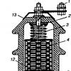
The valve discharger RVS (valve stationary arrester) is produced in the form of five standard elements: RVS-15, RVS-20, RVS-30, RVS-33 and RVS-35. These elements are used to complete arresters for voltages up to 220 kV. They are installed one on top of the other and connected in series. In fig. 2 shows a RVS element, consisting of a porcelain casing 1, inside which there are whitewash disks 2 and sets of spark gaps 4, consisting of several single spark gaps 3. Each set is enclosed in a porcelain cylinder 5. All spark gaps and whitewash disks are compressed by spiral springs 6. The porcelain casing is closed from the end sides by covers, under which a sealing rubber 7 is laid. The porcelain casing is reinforced with flanges 8, which are used to fasten the arrester to the supporting structure, as well as to connect to the busbars or wires. Sets of spark gaps are shunted by horseshoe-shaped resistors 9, designed to evenly distribute the voltage between them.
In fig. 3 shows a set of spark gaps, consisting of four single spark gaps. Each single spark gap includes two shaped brass electrodes 4, separated by a micanite spacer. Spark gaps are placed in a porcelain cylinder 3, closed at the top and bottom with brass caps 1. To the latter are attached horseshoe-shaped shunt resistors 2 made on the basis of carbocide. 
Rice. 3. Set of spark gaps of the arrester 
Rice. 4. Block of spark gaps of the RVM type arrester
Magneto-valve arresters of the RVM type have been used for a voltage of 35-500 kV. They differ from other types of arresters by the presence of blocks of magnetic spark gaps (Fig. 4). These spark gap building blocks, complemented by disc-type resistors, are manufactured for 35 kV. The block of magnetic spark gaps consists of a set of single spark gaps 2, separated by ring magnets 3. A single spark gap is made up of two concentrically located copper electrodes 6 and 8, between which an annular gap is formed 7. The arc arising in the gap rotates under the action of permanent magnets with high speed, which contributes to its rapid extinguishing A set of permanent magnets and single spark gaps is placed inside a porcelain cover 1, closed with steel covers 5. Magnets and copper electrodes are tightly compressed by a steel spring 4.
Arresters.
Completed by: Shlemina E.V.
Group: 7203
Faculty: EL
Checked by: V. T. Barchenko
St. Petersburg
1. Introduction ……………………………………………………………… ..3
2. Types of arresters …………………………………………………… ..3
3. Types of arresters …………………………………………………… ..4
4. General designation of the arrester ……………………………………… ..10
5. Volt-second characteristic …………………………………… ... 10
6. References …………………………………………………… ..13
Introduction.
Arrester- a device for closing electrical circuits by means of an electric discharge in a gas, vacuum or (less often) a solid dielectric; contains 2 or more electrodes separated by one or more discharge gap, the conductivity of which changes sharply when the potential difference between the electrodes becomes equal to some value determined under the given conditions - the breakdown voltage. Depending on the state of the discharge gap and the parameters of the electrical circuit, various forms of discharge can occur in the arresters: spark discharge, glow discharge (including corona discharge), arc discharge, high-frequency discharge, or mixed forms. Arresters are used in electrical engineering and various fields of radio electronics, in automation and experimental physics; they are used to protect electrical circuits and devices from overvoltage, to switch high-frequency and high-voltage electrical circuits, they are also used when measuring high voltages, and sometimes - as indicators of the degree of vacuum in vacuum systems.
Types of arresters.
In accordance with the functional purpose, there are two main types of arresters - protective and control. Protective arresters prevent excessive voltage build-up on the line or in the installation to which they are connected due to the breakdown of the arrester. The simplest types of arresters used to protect electrical networks are rod and horn arresters, consisting of two electrodes separated by an air gap (respectively, in the form of rods or curved horns). One of the electrodes is connected to the protected device, the other is grounded. Since the conductivity of the gas-discharge gap increases sharply during breakdown, the discharge current does not stop even after the voltage drops to a normal value. This current (the so-called follow current), which is the current of the system (or installation) to ground, leads to the operation of the relay protection, which entails a temporary interruption of the power supply to the installation or network section. Tripping of the relay protection in the case of alternating current can be prevented by using tube arresters that extinguish the follow current arc. In tubular arresters, the discharge gap is located in the channel of a tube made of insulating gas-generating material. Under the action of the heat generated in the follow current arc, the tube material decomposes with the release of a large amount of gas; in this case, the pressure in the tube channel rises, a gas flow is formed, extinguishing the arc when the accompanying current passes through a zero value. Tubular R. are used, as a rule, to protect AC power lines from lightning surges.
To ensure the effective operation of protective spark gaps, the breakdown voltage of the latter must be highly stable (independent of atmospheric conditions and the state of the electrodes). In addition, the volt-second characteristic of the discharge gap - the curve of the dependence of its breakdown voltage on the rate of voltage rise across it - should be relatively flat and lie below the volt-second characteristic of the insulation of the protected device. These requirements are met by valve arresters that provide protection against lightning and switching overvoltages for insulation of transformers and other electrical devices.
Control arresters are used to connect in a certain sequence various elements of pulse voltage generators, to connect the load to powerful pulsed current sources, as well as to connect electrical circuit elements of high voltage test equipment, etc. The simplest control arrester is a ball arrester consisting of two spherical electrodes, separated by a layer of gas. In some types of control spark gaps, the discharge between the electrodes is initiated at the right time by weakening the dielectric strength of the discharge gap (for example, by injecting an incandescent gas) or by means of an ignition pulse.
Types of arresters.
Tubular arrester serves to protect the insulation of overhead lines from atmospheric overvoltages and with other protection means to protect the insulation of electrical equipment of stations and substations with voltages from 3 kV to 110 kV, weak points on power lines and on approaches to substations. Tubular arresters are connected to live parts of power lines through an external spark gap.
It is a combination of two spark gaps connected in series (Fig. 1). The first (outer) rod gap S1 performs the function of limiting lightning overvoltages. The second (inner) gap S2 is located inside the gas generating material tube 1. One end of the tube is plugged with a grounded metal cap 2 with a rod electrode 3 attached to it. The other end of the tube is open and surrounded by a ring electrode 4. The inner gap serves to extinguish the electric arc and therefore it is also called arc suppression.

Rice. 1. Tubular arrester.
When limiting overvoltages, two stages of operation of a tubular arrester can be distinguished. At the first stage, when exposed to a lightning impulse, both spark gaps are broken through and a pulsed current flows through them, diverting the overvoltage energy to the ground and thereby limiting it. The volt-second characteristic of a tubular spark gap is mainly determined by the dimensions of the outer gap and has a form characteristic of all rod gaps in atmospheric air. The repeated breakdown of the ionized gaps by the operating voltage leads to the ignition of an electric arc between the electrodes. The second stage of the tubular arrester actuation begins - the extinguishing of the follow current arc. Under the action of the high temperature of the arc, a large amount of gas is released from the inner surface of the tube, which increases the pressure in it to 15 MPa. The gases rush to the open end of the tube and create a longitudinal blast with respect to the burning arc, which allows the arc to be extinguished at the first current crossing through the zero value. RT triggering is accompanied by the exhaust of a significant amount of incandescent ionized gases and a strong sound effect.
The tubular arrester is an arcing tube made of polyvinyl chloride, at different ends of which electrodes are fixed. One electrode is grounded, and the second is located at a short distance from the protected area (the distance is regulated depending on the voltage of the protected area). When an overvoltage occurs, both gaps are broken through: between the arrester and the protected area and between the two electrodes. As a result of the breakdown, intense gas generation occurs in the tube, and a longitudinal blast is formed through the exhaust hole, sufficient to extinguish the arc.
Valve arrester serves as a means of limiting overvoltages of electrical installations equipment arising during electrical circuit switching, lightning discharges, etc.


Rice. 2. Valve (single-phase) arrester.
It consists of spark gaps (1) and non-linear resistors (2), enclosed in a hermetically sealed porcelain cover (3), which protects the internal elements of the arrester from the external environment and ensures stability of characteristics.
The valve arrester consists of two main components: a multiple spark gap (consisting of several single-shot ones) and a working resistor (consisting of a series of drive discs). A multiple spark gap is connected in series with a running resistor. Due to the fact that the wilit changes its characteristics when humidified, the working resistor is hermetically sealed from the external environment. During overvoltage, a multiple spark gap breaks through, the task of the working resistor is to reduce the follow current to a value that can be successfully extinguished by spark gaps. Vilit has a special property - its resistance is nonlinear - it decreases with increasing current strength. This property allows more current to pass with less voltage drop. Thanks to this property, valve arresters got their name. Other advantages of valve arresters include quiet operation and no gas or flame emissions.
Magneto-valve arrester(RVMG) consists of several successive blocks with a magnetic spark gap and a corresponding number of whitened disks. Each block of magnetic spark gaps is an alternate connection of single spark gaps and permanent magnets, enclosed in a porcelain cylinder.
In the event of a breakdown in single spark gaps, an arc arises, which, due to the action of the magnetic field created by the ring magnet, begins to rotate at a high speed, which provides a faster, in comparison with valve arresters, arc extinguishing.

Rice. 3. Magnetic valve arrester.
Magneto-valve arresters of the RVM type have been used for a voltage of 35-500 kV. They differ from other types of arresters by the presence of blocks of magnetic spark gaps (Fig. 3). These spark gap building blocks, complemented by disc-type resistors, are manufactured for 35 kV. The block of magnetic spark gaps consists of a set of single spark gaps 2, separated by ring magnets 3. A single spark gap is made up of two concentrically located copper electrodes 6 and 8, between which an annular gap is formed 7. The arc arising in the gap rotates under the action of permanent magnets with high speed, which contributes to its rapid extinguishing A set of permanent magnets and single spark gaps is placed inside a porcelain cover 1, closed with steel covers 5. Magnets and copper electrodes are tightly compressed by a steel spring 4.
Surge suppressor Is a spark gap free arrester. The active part of such an arrester consists of a series of varistors, the conductivity of which is nonlinearly dependent on the applied voltage.
An arrester without spark gaps has a particularly fast response: when an overvoltage occurs, the resistance of such an arrester drops sharply, increasing immediately after the charge has passed (in less than 1 nanosecond). At the same time, the stability of the characteristics of varistors is maintained after many operations up to the end of the specified service life, which eliminates the need for operational maintenance.


Rice. 4. Surge suppressor.
1. Reinforcing elements
2. Varistors
3. Tire of new rubber
4. Protective tape
5. Flange
Arresters in a polymer housing can consist of one or several modules, each of which contains one column of varistors. Varistors do not have a "cumulative" effect; their current-voltage characteristic does not depend on the number of arrester operations. The silicone cover is applied to the active part by direct vacuum casting in a special holding machine. The flanges are connected to each other by two or more fiberglass reinforcing elements, which gives the arrester high mechanical characteristics. Due to the fact that the silicone insulation is applied directly to the variators, there is no air inside and, as a result, there are no internal partial discharges. In addition, the cooling conditions of the varistors are improved, which improves the energy absorption capacity of the arrester.
The arrester consists of an external insulator made of non-halogenated silicone rubber with end flanges and terminals made of stainless steel, aluminum or copper. The interior of the arrester consists of metal oxide varistors, steel gaskets, aluminum components, fiberglass ties and aramid fibers. Metal oxide varistors are agglomerate "tablets" consisting mainly of ZnO (90%) and other substances (more than 1%): Bi 2 O 3, Sb 2 O 3, NiO, Cr 2 O 3 .
Metal oxide varistors are coated with a layer of thin glass (<0,1 % веса), содержащим РbО. Силиконовая резина, используемая для внешней изоляции, обладает значительно более высокой гидрофобностью и стойкостью к воздействию ультрафиолетовой радиации, чем фарфоровая изоляция. Кроме того, применение полимерной изоляции снижает массогабаритные параметры ОПН, что расширяет возможность их применения. ОПН могут монтироваться по так называемой «перевернутой» схеме, когда подвод напряжения осуществляется снизу.
6-110 kV surge arresters with polymer insulation, in comparison with valve arresters, have a number of advantages:
1.varistors used in surge arresters have high stability, which
does not change during long-term operation;
2.high speed of operation of the arrester during switching and
lightning overvoltage;
3.Excellent peak characteristics of the arrester over a wide operating range
temperature;
4.the use of varistors in one column design allows
provide a particularly deep limitation of stresses and, accordingly, more
high reliability of equipment operation and improvement of network parameters;
5.Reduction of size and weight of surge arresters by 10 - 20 times allows them to be installed
directly near the protected equipment;
6.high mechanical strength and low weight of the arrester allows
install them on 6-110 kV overhead lines without strengthening the structure of the supports;
7. Arresters in a polymer casing do not require special maintenance, do not
damaged during transportation and storage;
8.small mass dimensions of the surge arrester make it easy to carry out their installation when
minimal use of technology.
General designation of an arrester.

Rice. 5. Designation of arresters.
1. General designation of the arrester
2. Tubular arrester
3. Valve-type and solenoid-valve arrester
4. surge arrester
During commutations, as well as due to atmospheric discharges in electrical installations, voltage pulses often occur - overvoltage, significantly exceeding the nominal. The electrical insulation of the equipment should not be damaged in this case and is selected with an appropriate margin. However, the resulting overvoltages often exceed this margin, and the insulation then gets damaged - breaks through, which can lead to serious accidents. To limit the arising overvoltages, and, consequently, to reduce the requirements for the level of electrical insulation (reduce the cost of equipment), arresters are used.
Arrester is an electrical apparatus, the spark gap of which breaks through at a certain value of the applied voltage, thereby limiting overvoltage in the installation.
The arrester consists of electrodes with a spark gap between them and an arcing device. One of the electrodes is connected to the protected circuit, the other is grounded.
If the curve 1 (Fig. 3-6) is the rated voltage, and curve 3 is the volt-second characteristic of the equipment insulation (i.e. the time during which the insulation can withstand this overvoltage without being damaged), then the volt-second characteristic of the arrester should be determined by curve 2 . When an overvoltage occurs (curve 4) the spark gap of the arrester breaks down earlier (point O) than the equipment insulation. After breakdown, the line (network) is grounded through the arrester resistance or short-circuited. In this case, the voltage on the line is determined by the value of the current through the arrester, the arrester and grounding resistance.
The voltage drop across the arrester when a pulse current of a given value and shape flows is called the residual voltage. The lower this voltage, the better the quality of the arrester.
After the breakdown of the spark gap from the voltage pulse, its spark gap is ionized and is easily broken by the phase voltage. A short circuit to ground occurs, and a power frequency current, which is called a follower, flows through the arrester. To avoid the operation of the protection and the shutdown of the equipment, the arrester must disconnect the follow current in the shortest possible time (approximately in the half-cycle of the industrial frequency).
Rice. 3-6. Volt-second characteristics.
The following requirements are imposed on arresters:
1. The volt-second characteristic of the arrester must be lower than that of the protected object.
2. The spark gap of the arrester must have a certain guaranteed dielectric strength at power frequency.
3. Residual voltage across the arrester, and characterizing its limiting capacity, should not exceed values that are dangerous for the isolation of equipment.
4. Follow current must be disconnected for a short time.
5. The arrester must allow a large number of operations without inspection and repair.
Tubular arresters. The arrester (Fig. 3-7) is an arcing tube 3 made of polyvinyl chloride brand "vinylplast", at the ends of which metal tips are fixed: upper, closed, 2 and lower, open, 7. A rod electrode is placed inside the tube 4, which is attached to the shank 9 of the upper tip. The second electrode of the internal spark gap is washer b, fixed in the lower tip. With the help of clamps 5, the lower tip (arrester) is fixed to the grounded structure. The actuation strip indicator is attached to the lower tip. 8, the free end of which is bent and wound inside the tip. When the spark gap is triggered, the end of the pointer is ejected by the gas blast, and the tape is straightened.

Rice. 3-7. General view of a tubular spark gap.
In order to unload the insulating material of the arrester from the electric field at the nominal mode, the arrester is separated from the line by an external (lnar) spark gap, which is regulated by an extension cord (horn) 1.
When an overvoltage occurs, both gaps break through (lvn and lout). An arc arising in the tube causes strong gas generation from the walls of the tube. The gases rush through the exhaust hole in the washer b and the open tip, forming an intense longitudinal blast, which extinguishes the arc when the current passes through zero, while the arc also extinguishes at the interval lnap. The shutdown is accompanied by a large emission of flames and gases (at U= 35 kV A = 3m, B = 1.5 m). The volume occupied by flames and gases should not contain any live parts. The maximum cut-off current is determined by the strength of the tube and, for example, for 6-35 kV PTV arresters, it is 12 kA. The limiting breaking currents of arresters with fiber-bakelite tubes are lower than those of arresters with vinyl plastic tubes.
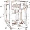
Valve arresters. The valve arrester (Fig. 3-8, a) consists of two main parts: a block of spark gaps 4, which includes several series-connected single spark gaps 3 (fig. 3-8, b), shunted by horseshoe-shaped nonlinear resistors 9, designed to equalize the voltage distribution, and a working resistor made up of a set of series-connected Vilit disks 2. The spark gaps are enclosed in porcelain cylinders 5.
The spark gap block is connected in series with the working resistor, covered with a porcelain casing 1, compressed by a spiral spring 6 and sealed with ozone-resistant rubber 7. The need for sealing is due to the hygroscopicity of vilit, which changes its characteristics when moistened. The arrester is attached with flanges 8 to the cast iron base (not shown in the figure).
The phase wire of the high voltage line connects to the bolt on the cover. The grounding conductor is connected to the cast iron base of the arrester directly or via a trip counter.
The spark gap works as follows. When an overvoltage occurs, spark gaps break through and the pulse current goes through the working resistor to the ground. The follow current is limited by an operating resistor to a value at which the arc can be extinguished by spark gaps. A single gap is able to turn off the current with an amplitude of 80-100. And at an effective recovery voltage of 1-1.5 kV. The number of spark gaps and the number of resistor discs are selected based on the specified conditions. In this case, the arc will extinguish in one half-cycle.


Rice. 3-8. Ventel arrester.

Rice. 3-9. Block with magnetic spark gaps.
A wilita resistor is characterized by the non-linearity of its resistance. With increasing current, the resistance value decreases. This allows a large current to pass through the resistor with a small voltage drop (because of this, the arresters are named in valves). The voltage across the arrester changes practically little over a wide range of currents. As the current approaches zero, the resistance increases sharply, reducing the current to zero before its natural zero crossing. This circumstance makes it easier to extinguish the arc in single spark gaps.
Valve arresters operate silently and without any emission of gases or flames. To fix the number of operations, special (electromagnetic, electromechanical, etc.) counters are installed. Valve arresters are made for voltages up to 220 kV and are designed to protect the insulation of electrical equipment from atmospheric overvoltages. They are used in open and closed electrical installations with a frequency of 50 Hz. Arresters for 3, 6 and 10 kV differ from each other only in the number of spark gaps and the number of power resistors, as well as in size. Arresters for rated voltages of 15, 20 and 35 kV consist of one standard element, similar to that shown in Fig. 3-8, a; arresters for voltages of 60 kV and above - of three or more standard elements connected in series with a rated voltage of 15, 20 or 35 kV.
Magnetoventilation arresters (RMVG). These arresters are designed for rated voltages of 150-500 kV. They are assembled from standard blocks (30 kV) with magnetic spark gaps and the corresponding number of disks for power resistors.
The block of magnetic spark gaps (Fig. 3-9) is a set (here four) of single spark gaps 2, alternating with permanent magnets 3 ring shape. The whole device is housed in a porcelain cylinder 1 and closed with steel covers 5. All elements are fastened inside the cylinder by spring pressure 4. Each block is shunted with high-resistance non-linear resistors.
A single magnetic spark gap consists of two concentrically located copper electrodes b and 8. The gap 7 between them forms a spark gap. Ring magnets 3 create a magnetic field in the slot (480-640 A / cm).
The arc arising in the slot begins to rotate along the annular slot at high speed. Compared to conventional spark gaps, the throughput and arcing capacity of the magnetic spark gap is much higher.
DC arresters. It is not possible to use arresters with conventional spark gaps to protect DC electrical equipment. The voltage drop across the spark gap after its breakdown will be only 20-30 V, and an extremely large number of gaps will be required to extinguish the arc; the breakdown voltage will be excessively high and the insulation will not be protected.
DC arresters are manufactured with arc extinguishing devices. Thus, DC magnetic arresters of the RMBV series consist of spark gaps with an arc suppression chamber (shunted or not shunted by resistors with high-resistance nonlinear resistances), a working non-linear power resistor unit and an arc-extinguishing spark gap with permanent magnets. Structurally, they are made similar to valve arresters.
Magnetic arrester of the RAS-1 type - a reusable arrester with reduced pressure inside the housing, designed to protect the excitation windings of synchronous machines against overvoltage. The arrester has a breakdown voltage setting adjustment range of 1200-3500 V (peak value) and allows a current to flow up to 5000 A (peak value) with an average current value for 1 s up to 1000 A. The nominal voltage of the arrester is 1000 V DC.
28.09.2015
Device, appearance
Regardless of the type, arresters must have spark gaps, as well as working and shunting resistors. Further, the structure is placed in a porcelain body and closed in all flanges using reinforcing mortars. This is how we see them in substations and switchgears.
Moisture-resistant paint and enamel are used, which are placed on top of the reinforcement. Arresters differ in class voltage, which determines the number of mikanite washers (spark gaps are produced from them), as well as their ratio with the resistance of the working resistor.
During the operation of the switchgear, when the voltage increases to breakdown, the resistance of the working resistor, on the contrary, falls, which indicates its nonlinearity.
Vilite (rarely tervite) disks are used as the basis for a working resistor. They are distinguished by such property as hygroscopicity, which explains the need for tightness of the arrester housing and connecting joints.
Basic types of arresters
- RVN, RVO, RVE, RVP and RVS arresters are used exclusively to protect switchgear and other high-voltage equipment from failures during a thunderstorm. In the latter, the pulse duration is shorter in comparison with the switching ones, which is important for these types of devices, because their capabilities are limited by the ability to extinguish the arc by spark gaps. All leads come from the composition of such arresters: the design consists of spark gaps and working resistance connected one after another.
- RVRD, RVMG and RVM: these arresters on any switchgear are capable of extinguishing the arc. The possibility is achieved due to the magnetic field, which acts from permanent magnets: in the spark gap, the arc stretches and disappears. Devices of these types are able not only to protect the switchgear or other high-voltage equipment from the destructive effects of lightning discharges, but also to protect against short-duration switching overvoltages.
- RVMK arresters will be the best protection against switching overvoltages, they have the following modules in their design:
- spark, consisting exclusively of spark gaps,
- valve, which is represented only by resistors,
- the main one, where both working resistors and spark gaps are located.
The use of lightning rods does not completely exclude lightning damage to electrical installations, especially power lines, since the probability of lightning breakthrough for overhead power lines can be relatively high, and, moreover, they are often performed without wire protection at all. Overvoltage waves that occur on lines during lightning strikes reach substations (which is why they are called incident waves) and can pose a danger to the insulation of equipment installed there.
To prevent damage to any insulating structure, turn on in parallel to it spark gap, volt-second (the characteristic of which must lie below the volt-second characteristic of the protected insulation. If this condition is met, the drop of the overvoltage wave will in all cases cause a breakdown of the spark gap, followed by a sharp drop ("cut") of the voltage across the spark gap and of the protected insulation. a pulse current through the spark gap will begin to flow a current due to the voltage of the industrial frequency of the electrical installation - the accompanying current.
In installations with a grounded neutral or in the event of a spark gap breakdown in two or three phases, the follow current arc may not extinguish on its own, and the impulse breakdown in this case will turn into a stable short circuit, which will lead to the installation shutdown. Therefore, in order to avoid such a shutdown of the installation, it is necessary to extinguish the follow current arc through the spark gap.
Devices that provide not only insulation protection against overvoltage, but also extinguishing the follow current arc for a time less than the duration of the relay protection, are called protective arresters unlike conventional spark gaps, which are commonly called protective gaps(PZ).
Tubular arresters together with are the main types of arresters. They differ in the principle of arc extinguishing of the follow current. In tubular arresters, the arc is extinguished by creating an intense longitudinal blast, and in valve arresters, the arc is extinguished due to a decrease in the follow current using an additional resistance connected in series with the spark gap.
Tubular spark gap (Fig. 1, a) represents tube 2 made of insulating gas-generating material, inside of which there is an arcing unregulated gap S1 formed by rod electrode 3 and flange 4. The spark gap is separated from the operating voltage by an external spark gap, since tube 2 is not designed for long-term presence under voltage due to the decomposition of the gas-generating material under the influence of leakage currents. The second flange 1 of the arrester is grounded.

Rice. 1. Tubular arrester: a - device and switching circuit, b - conventional designation on the diagrams, c - voltage across the arrester, d - equivalent circuit.
At overvoltage in the network(Fig. 1, c) both spark gaps break through and the overvoltage wave (curve 1) is cut off. An accompanying current begins to flow along the path created by the pulsed discharge, and the spark discharge turns into an arc discharge. Under the action of the high temperature of the arc channel of the accompanying current, the material of the tube decomposes with the release of a large amount of gases, the pressure in it increases sharply (up to tens of atmospheres) and the gases are forced out through the opening of the flange 4, creating an intense longitudinal blast. As a result, the arc is extinguished the first time the current passes through zero.
When the spark gap is triggered, incandescent ionized gases are emitted from it in the form of a torch 5 1.5 - 3.5 m long and 1 - 2.5 m wide (depending on the rated voltage of the spark gap) and a sound resembling a shot is heard. Therefore, in order to prevent phase-to-phase faults, when installing arresters, you need to ensure that the current-carrying parts of adjacent phases do not get into the exhaust zone. The triggering voltage of the arresters can be adjusted by changing the distance of the external spark gap, but they cannot be reduced below a certain minimum, as this causes too frequent triggering of the arresters and their increased wear.
Since the electric field of the rod electrodes of the tubular spark gap is highly inhomogeneous, its volt-second characteristic has a falling character in the area up to 6 - 8 μs, which is poorly consistent with the flat volt-second characteristics of transformers and electrical machines. For successful arc extinguishing, a certain intensity of gas formation is required, therefore there is a lower limit of the currents to be switched off, at which the arrester can still extinguish the arc within 1 - 2 half-periods.
The upper limit of the interrupted currents is also limited, since too intense gassing can lead to the destruction of the arrester (rupture of the tube or breakdown of the flanges).
The range of interrupted currents is indicated in the designation of the type of arrester, for example, RTV 35 / (0.5 - 2.5) means a tubular arrester of 0.5 - 2.5 vinyl plastic for 35 kV with a range of interrupted currents of 0.5 - 2.5 kA.
With a decrease in the length of the arc-suppression gap and an increase in its diameter, both limits of the disconnected currents of the arrester shift towards larger values.
Since the operation of the arrester is accompanied by the burning out of a part of the material of the arc suppression tube, then after 8 - 10 operations, when the diameter increases by 20 - 25% compared to the initial one, the arrester becomes unusable (since the limits of the currents cut off by it change) and must be replaced.
To account for the number of operations, the tubular arresters are equipped with an actuation indicator in the form of a metal tape 6 (see Fig. 1, a), which is unbent by the gases emitted by the arrester. Currently, the industry produces tubular arresters type RTF, in which the gas is generated by a fiber tube, and PTB type with a vinyl plastic tube.
Due to the low mechanical strength of the fiber, it is enclosed in a thick tube of bakelized paper, which, to reduce its hygroscopicity, is covered with a moisture-resistant varnish (usually perchlorovinyl enamel), which can withstand the weathering of summer and winter periods well. A feature of the RTF type arresters is the presence of a chamber at the closed end of the tube, which enhances the longitudinal blowing when the current passes through the zero value and thereby contributes to the extinguishing of the arc.
In RTV arresters, gas is generated by a vinyl plastic tube, which has a higher gas-generating ability and insulating properties that are well preserved even when working in the open air in any weather. RTV arresters have a simpler design (they do not have an internal chamber, do not require varnishing) and higher upper limits of interrupted currents (15 kA instead of 7-10 kA for RTF arresters).
Rice. 2. Tubular arrester RTV-20-2 / 10
For operation in networks with very large interrupted currents (up to 30 kA), reinforced arresters of the RTVU type are produced, the increased mechanical strength of which is achieved by winding a vinyl plastic tube with layers of glass tape impregnated with a weather-resistant epoxy compound.
The impulse throughput of tubular arresters, which pass practically the entire lightning current through themselves when it strikes the line, is quite high and amounts to 30-70 kA.
The choice of tubular arresters is made according to the rated voltage of the network and the limits of the short-circuit currents of the network at the point of their installation. Maximum short-circuit current calculated under the condition that all network elements (lines, transformers, generators) are turned on, taking into account the aperiodic component of the short-circuit current, the minimum current - with a network circuit with partially turned off elements (for example, for major repairs) and without taking into account the aperiodic component. The found limits of the short-circuit current. must fit within the limits of the cut-off currents of the tubular arrester.
Tubular arresters are produced for voltages from 3 to 220 kV, the interrupted currents are in the range from 0.2 - 7 and 1.5 - 30 kA at a voltage of 3 - 35 kV to 0.4 - 7 and 2.2 - 30 kA at a voltage 110 kV. The 220 kV arrester consists of two 110 kV tubular arresters connected by a steel cage with exhaust pipes.
The main disadvantages of tubular arresters are the presence of an exhaust zone, a steep cutoff of the overvoltage wave, short-circuiting (albeit short-term) of lines to ground and a particularly steep volt-second characteristic, which excludes the possibility of widespread use of tubular arresters as a protection device for substation equipment. The disadvantage of tubular arresters is also the presence of limiting interrupted currents, which complicates their production and operation.
Due to their simplicity and low cost, tubular arresters are widely used as auxiliary means for protecting substations, for protecting low-power and low-critical substations, as well as individual sections of lines.
Currently, tube and valve arresters are gradually being replaced by nonlinear voltage limiters (arresters)... They are series-connected metal oxide varistors (non-linear resistors) without spark gaps, enclosed in a porcelain or polymer case.