Seal
Repair Vestel TVs
Vestel VR2106TS chassis 11AK-30. Narrow vertical stripe- check R645 2k2, replace capacitor C627 430n250v.
Vestel VR54TF Chassis 11AK30A11. Processor ST92195C3B1/OEO VESTEL/T3X210. Power supply does not start, Q801 P6NK60ZF and R836 burned out (there is a jumper in the earlier chassis instead of R836) after replacing the burnt parts and turning on the TV, Q801 and R836 burned out again, after a thorough check, the IC800 MC44608 chip turned out to be faulty and again, when replacing ALL burnt parts, the TV worked fine. If Q801 has a short circuit on all pins, feel free to change IC800 MC44608 the simplest check of this mikruha between 4 and 5 legs should be about 33 k, if 0, then it needs to be changed.
Vestel VR74STS-2915 The raster is strongly stretched horizontally. The correction is not adjustable. Breakdown D606 UF5407 in a diode modulator. After replacement, the correction does not work. Q602 9NQ20T also turned out to be faulty. Detected only by replacement. The transistor is not broken, you can open and close the source-drain, but it does not work in correction circuits.
VESTEL VR 54TFF-2115 on some programs the sound starts to wheeze. It was treated by flashing the memory for the 11AK30 chassis.
VESTEL VR54TS-2145 . TV turns on. No raster, no sound, although the LED on the front panel indicates the operation of the TV (glows green). Faulty transistor Q601 STX112. The transistor in the diagram is shown as a normal NPN transistor. In fact, it is composite and cannot be changed with an ordinary NPN transistor.
VESTEL 2151. When turned on from standby mode, the power supply "tsikal". The test showed an underestimation of the output voltages from the UPS in operating mode. The Zener diode TL431 turned out to be faulty.
Chassis 11AK37. Large horizontal size. Vertical lines are concave along the edges of the screen (correction does not work). The reason is a broken coil L603.
Vestel 2151 When turned on from the duty room, "tsikal". The test showed an underestimation of the output voltages from the UPS in operating mode. The zener diode TL431 turned out to be faulty.
VESTEL VR 54TF-2145 not tuned to cable channel in the range of 150-160 mHz. An attempt to rearrange the TUNER options to SERVICE from a nearby TV resulted in the loss of the VL range. Flashing many firmwares from 11AK30 did not help restore the range. Turning to the Service manual, I installed the options of one of the six possible TUNERs for this chassis, Alps TEDE9-004A which came up under the TUNER TAEM-G804D installed in the TV.
VESTEL 2151T. Chassis 11AK19-5. E there is sound, no visible raster. As the accelerating voltage increases, a blue raster appears with retrace lines. I started with the firmware, it did not help (I put the memory on the socket). This AK19 chassis turns on even without MXS memory, there is a normal raster with noise. If, at the same time, a microcircuit is inserted into the panel directly on the working TV, then everything works. There is an image, sound, settings work. You turn it off to the duty one, then back to the worker and again it does not work. The reason is a malfunction of the ABB. Pin 5 of the TDA6108J is “planted” (ABB output was 20 ohms in one direction), there is also a 6.2 volt zener diode leak.
VESTEL 2151 The horizontal transistor is heated and flies. Changed four times. The reason is the pre-output stage, replace the STX112. C607 10.0x50v failure is also possible.
Vestel (chassis 11AK30). The output voltages from the power supply are too low(UPS). Faulty D802 (BA159). After replacement, the DR indication LED lights up green, after a second, red, and so it repeats. Replaced IC801(SFH617A).
Vestel VR37TS-1445. Won't turn on from standby. The video processor STV2246H gets very hot. Replacing the video processor. Replaced by STV2249H.
Vestel Chassis 11AK33 . After the start, he goes to duty. Neither a careful visual inspection, nor a thorough check of all hot elements (memory, processor, IP, SR, CR) gave anything. The output correction transistor is intact (if it has flown, then everything is clear), the open resistor is normal, the inductor - well, as from a showcase. In short, I pulled this throttle, and on the LC meter. And there are short turns. When disassembling the inductor, the turns turned out to be fried at the beginning of the winding (not visually visible). The throttle was successfully disassembled and rewound. The telly worked. By the way, to check the throttle, if there are no devices, you can substitute DRT 1-1 from 3USCT for a while. If BDX53BFI has flown and there is no native one, then you can put BUT11, BUT12 or BUX84. If the correction is assembled on a field effect transistor, then instead of BUK444 you can put 6N60, 6N80 and even BUZ90. P/S. The defect is typical, inherent in all VESTELs on 11AK ....
Vestel 5165. Chassis 11AK30. The standby indicator is on, the TV does not switch to the operating mode. The secondary voltages of the power supply are significantly underestimated. The search led to the capacitor C827 - 4700.0x16V. After replacing it, everything worked fine.
VESTEL chassis 11AK19P4 . When turned on, immediately returns to standby mode. The PSU key transistor heats up more than usual. When checking the parts of the PSU, a leakage of the diode D807 (BA159) was detected. The ringing defect was not detected. After replacing the diode everything is OK.
VESTEL 1465 Chassis 11AK20. PSU does not start, LED blinks. The PSU has an MC44603R chip, there is no optocoupler. First I checked the entire piping of the MC44603 and the short circuit at the output, everything is normal. I replaced the chip, no luck. When replacing the MC44603 strapping in detail, I found a broken C810 chip capacitor (0.1 microfarad). After replacing it with a regular capacitor by soldering to the tracks of the board, the TV worked fine.
Vestel VR74STS-2915 Chassis 11AK37. The screen does not light up. Is there sound, the channels are switched. Horizontal scan under voltage 145V, but no excitation, H.OUT pulses are not received from the 48th leg of the IC403 microcircuit. Upon inspection, a burnt resistor R639 and a BURNED capacitor C619 were revealed. This capacitor, together with C618, makes up the impulse voltage divider. With the loss of capacitance C619, the amplitude of the pulses increases significantly and goes along the circuit R639 (burned out) - diode D407 (broken) - R426 (burned out) - 49 leg IC403. After replacing the failed elements, the TV worked normally.
Vestel VR5465TS (AK30) . Does not turn on, indicator does not light. On examination, ring non-solders of the m / sx stabilizer IC804 LM7805 were revealed. After the non-soldering is eliminated, the standby mode indicator lights up, but when you try to switch to the operating mode, the TV starts up and after a few seconds goes into standby mode. When you decrease SCREEN on TDKS TV starts, but the image is dark. Voltages are normal. The fault was in the L601 throttle (Q603 base).
Vestel VR54TF-2145 (chassis 11AK30A4). When you turn on the TV from standby mode, the horizontal scan start delay in 20-30 seconds. If the TV was completely turned off for a long time, the turn-on delay time increased. Faulty C613 10.0x63 in the base circuit of the horizontal scanning transistor.
Entering the service menu for Vestel TVs(Chassis 11AK19P) Being in the menu, press sequentially: 4,7,2,5. Suitable for almost all Vestel models.
At the beginning of the article, malfunctions and possible causes of VESTEL TVs are described.
Vestel VR54TF-2145 (chassis 11AK30A4). When you turn on the TV from
standby mode, the delay in starting horizontal scanning is approximately half a minute or more if the TV has been turned off for a long time.
It turned out to be a faulty capacitor in the base circuit of the C613 line-scan transistor 10.0 x 63V.
VESTEL MODEL: 7216 GST PIP Chassis 11AK19B-1
The horizontal transistor is on - check the TMS is a small transformer in the HOT base (output trans SR). All these Turkish chassis suffer from non-solders on the deflection coil connector and in general in the line scan area.
A frequent fault for the failure of line transistors is their marriage! It is better (if any) to take a working transistor from the board of an unusable TV.
Vestel ch. 11AK30A11 Fault: The line transistor BU808DFI is broken.
Completed work: Replacement with BU808DFX did not work. When you press the P + panel for 2-5 seconds. secondary voltages appeared, but 8V was lowered to 4V. The check showed that the percent is faulty. STV2246H. Leg 45 (VCC1) shorted to GND. Since the TV was visited by another master, the values \u200b\u200bof some soldered parts were checked (according to fresh soldering). C618 was 5.6nF instead of 7.5nF (as in the diagram). Still had to change the memory.
Vestel 14" chassis 11AK36 A2
Fault: TV does not work. The power supply is OK. In standby mode, all voltages are normal, but when you try to start 114 volts, it drops to 50 volts.
Reason: dried up C820 47.0x160 and C827 33.0x160.
TV Vestel (different models, common chassis) the firmware crashes: you cannot select the VHF & UHF bands in the menu, but S1-S10 (CATV) appears, plus the power switch sparks. I didn’t find how to switch in the service manual, I took the firmware from a similar model and completely reflashed the microcircuit. There were 3-4 models with this malfunction.
Entering the service menu for Vestel TVs (Chassis 11AK19P) While in the menu, press in sequence: 4,7,2,5 Fits almost all Vestel models, as well as TV Eldorado.
Chassis 11AK19 (VESTEL, ELDORADO, etc.) often there is a defect in the form of twitching and tearing of the image, a breakdown in synchronization. This is due to poor contact of the HV wire in FBT 1142.5086 (poor design or execution). Eliminated by rigid fixation of this wire relative to the FBT case. In analog HR7950 this defect was never observed.
Vestel. TDA8842 + TDA6108 Fault: Bright screen illumination with LOH (reverse lines). After a few seconds, protection is activated and the TV goes into standby mode. The power supply of the video amplifier +200 is normal. There is no signal at the TDA6108 RGB inputs. One of the TDA6108 outputs turned out to be broken (short circuit to ground), while the TDA8842 blocks the outputs. TDA6108 can be replaced with TDA6107. Only in this case, it is necessary to additionally install 3 protective diodes at the outputs according to the TDA6107 wiring diagram.
Vestel VR37TS ch. 11AK36 The malfunction appears after 30-40 minutes. On bright scenes, the horizontal size narrows, at this moment + V drops from 115v to 102v, the picture changes, the size is restored. The power supply is assembled on m / s, UC3843 R804 increased its value to 7 kom, it stands between the 4th and 8th leg of the m / s.
Vestel VR5465TS (AK30) Fault: does not turn on, the indicator does not light. On examination, ring non-propane m / s stabilizer IC804 LM7805 was found. After the non-soldering is eliminated, the standby mode indicator lights up, but when you try to switch to the operating mode, the TV starts up and after a few seconds goes into standby mode. When you decrease SCREEN on TDKS TV starts, but the image is dark. Voltages are normal.
The fault was in the L601 throttle (Q603 base). The problem was fixed after replacement.
VESTEL 72cm (chassis 11AK37) Large horizontal size, vertical lines are concave along the edges (correction does not work). The reason is a broken coil L603. It was possible to restore, because. the break was near the exit.
Vestel ch. 11AK56-6 Fault: more often there is no sound (sometimes it appears). Guilt in the capacitor C165 (26 legs of the TDA9551 processor (SNDPLL)).
Vestel 2151 Fault: when turned on from the duty room, it “poked”. The test showed an underestimation of the output voltages from the UPS in operating mode. The zener diode TL431 turned out to be faulty.
Vestel chassis 11AK30A11 The UHF range disappears, the soldering of the CTF 5510A Thomson tuner did not give a result, I had to change it to what it was - TDQ-6L / 125SAA40-10007A. The TV worked.
Vestel VR2106TS Chassis 11AK-30 Narrow vertical strip - check R645 2k2, replace capacitor C627 430n250v.
Vestel VR2106TS ch. 11AK30-A14 Malfunction: there is no launch of a horizontal scan, when checking the binding of a horizontal scan, a swollen capacitance C619 100n / 250V was detected. After replacing it, the TV worked properly.
Vestel 5165. Chassis 11AK30. Fault: the standby indicator is on, in
TV does not switch to operating mode. Secondary power supply voltages
significantly underestimated. Troubleshooting led to the capacitor C827 - 4700.0x16V. After
replacing it worked fine.
Vestel 21″ TFS ch. 11AK30A14 Malfunction: when launching a line flash across the screen with a snake, crackling, no image, HOT whole. Faulty quartz 4.433619. After the replacement, the image is there, but without PAL and SECAM. I put this quartz through a 18pF capacitance to ground, and replaced the C427 capacitor with 1mf / 50v, the color went on in both systems.
Vestel VR74STF Chassis 11AK37 Processor ST 92195C381/OEO The TV starts up, but there is almost no image and there is simply no other sound in the BG standard in the settings, it does not remember the settings - the memory 24C08 is killed - after replacing the clean memory, I set all the options manually in the service mode (from another TV). Entering the TUITANIUM-210 service menu: on the remote control, the “M” button is the main menu, then buttons 4,7,2,5 and options:
OSD 050 ; IF1004; IF2 077 ; IF3003; IF4062; AGC037; VLIN 007 ; RGB 007 ; VSOF -03 ; VPOF -01 ; HSOF -01 ; HPOF -08 ; HTOF -01 ; WR025 ; WG025 ; BB 025 ; BR030; BG030 ; APR 004 ; FMP1 011 ; NIP1 028 ; SCP1011; SEC1 081 ; FMP2013 ; NIP2 045 ; SCP2008; SEC2049; F1H 00001011 ; F1L 01010010 ; F2H 00011101 ; F2L 00000010 ; BS1 00000001 ;
BS2 00000010; BS3 00001000; CB 10001110; OP1 11101101; OP2 00011001; OP3 11101101;
OP4 01111111; OP5 11110011; TX1 01011110; GEOM 00101100; OP8 00000000 . If you press the green button, then enter the submenu for setting the geometry: VSIZ 031; VPOS 019; VSCO 003; VCCO 007; HSIZ 008; HPOS 034; HPIN 011; HCCO 013; HTRP 014; VZSZ 006.
The exit from the menu is also the "M" button on the remote control. This is all on a diagonal of 74 cm with a flat screen. ATTENTION! Before changing the settings, they must first be overwritten.
Vestel VR54TF Chassis 11AK30A11 Processor ST92195C3B1/OEO VESTEL/T3X210 The power supply does not start, the Q801 P6NK60ZF and R836 burned out (there is a jumper in the earlier chassis instead of R836) after replacing the burnt parts and turning on the TV, Q801 and R836 burned out again, after a thorough check, the IC800 MC44608 chip turned out to be faulty and again, when replacing ALL burnt parts, the TV worked great. If Q801 has a short circuit on all pins, feel free to change IC800 MC44608 the simplest check of this mikruhi between 4 and 5 legs should be about 33 k, if 0 then it needs to be changed.
VESTEL VR2106TS Chassis PAEX0185 When turned on, the red LED is on, it does not respond to the keyboard, the power supply is in operating mode, there is no line start, a slight heating of N902 - ST8131. The culprit is C209 470/16v - to / z. 8v power supply, installed next to the tuner. A trifle, but the 3rd case this year.
Vestel VR74STS-2915 Fault: the raster is strongly stretched horizontally. The correction is not adjustable. Breakdown D606 UF5407 in a diode modulator. After replacement, the correction does not work. Q602 9NQ20T also turned out to be faulty. Detected only by replacement. The transistor is not broken, you can open and close the source-drain, but it does not work in correction circuits.
VESTEL VR 54TFF-2115 periodically and not every day, on some programs, the sound began to grunt. It was treated by flashing the memory for the 11AK30 chassis.
VESTEL chassis PAEX0185
Weak distorted sound. Voltages on TDA7267A:
1 leg (VS) - 15V,
2 (OUT) - 15V,
3 (SVR) - 15V.
I thought the TDA7267A was faulty, but when I started measuring pin 4 (IN), the sound became clear and loud. I remove the probe - the sound deteriorates, I touch it - it is restored. Using the selection method, I picked up a resistor for shunting 4 legs to the mass - up to 390 kOhm the sound disappears, at 470 kOhm it appears. Put 820 kOhm. Now the voltages on the TDA7267A are as follows:
1 - 15V,
2 - 10V,
3 - 15V,
4 - about 1V
The chip itself is a little warm.
VESTEL VR 54TF-2145 not tuned to a cable channel in the range of 150-160 mHz. An attempt to rearrange the TUNER options to SERVICE from a nearby TV resulted in the loss of the VL range. Flashing many firmwares from 11AK30 did not help restore the range. Turning to the Service manual, I installed the options of one of the six possible TUNERs for this chassis, Alps TEDE9-004A which came under the TUNER TAEM-G804D installed in the TV.
Vestel chassis 11AK30 Vertical stripe, lit R645 - 2k2. Guilty capacitor C627 - 430n / 250V
VESTEL-2151T. Chassis 11AK19-5 (LLC "TELEBALT"). Fault: there is sound, there is no visible raster. As the accelerating voltage increases, a blue raster appears with retrace lines. I started with the firmware, it did not help (I put the memory on the socket). This AK19 chassis turns on even without MXS memory, there is a normal raster with noise. If, at the same time, a microcircuit is inserted into the panel directly on the working TV, then everything works. There is an image, sound, settings work. You turn it off to the duty one, then back to the worker and again it does not work. The reason is a malfunction of the ABB. Pin 5 of the TDA6108J is “planted” (ABB output was 20 ohms in one direction), there is also a 6.2 volt zener diode leak.
VESTEL 2151 Malfunction: the line transistor is heated and flies.
The reason is in the pre-output stage, replace the STX112, the C607 10.0 x 50v may fail, as well as the substandard transistor itself.
Vestel chassis 11AK19PRO When turned on, the green LED lights up, all the voltages from the PSU are normal, but the kin is locked, there is a glow, it can be in this mode as long as you like, in my case the tube is narrow-necked (Chinese), the TV worked out a 3-year warranty on the fourth tube died, when adding a screen - the kin works, there is a picture and sound, the reason was found out only after a new kin was added, the ABB worked and the tube was locked!
Vestel (chassis 11AK30) Fault: The output voltages from the power supply unit (UPS) are too low. Faulty D802 (BA159). After replacement, the DR indication LED lights up green, after a second, red, and so it repeats. Replaced IC801(SFH617A).
Vestel chassis 11AK30 There is no horizontal scan start, the voltage is too low + 14V. Reason - defective C833 - 470uF / 16V
West 21E11. Fault: no picture and no sound. Check and, if necessary, replace VD854 (open).
Vestel chassis 11AK30A14 When turned on, the green LED lights up and immediately goes into the duty room, The voltages rise at the moment of switching on, and correspond to the diagram, C810 is faulty
Vestel ch. 11AK30 When turned on, the green LED lights up and immediately goes into the duty room. The reason is the video amplifier TDA6107. The most interesting thing is that at the same time, an ohm resistor of 200V. the amplifier does not break and does not burn.
VESTEL chassis 11AK28/41/52/53 and the like, where there is a personnel STV9379FA or TDA8177F. Malfunction: there are such cases when it cuts off the neck of the kinescope. The fact is that the Turkish developers did not take care that when one of the supply voltages to the frame scan disappears, the TV goes into protection. And so one resistor breaks, the beam wraps and you're done. What should I do to prevent this from happening in the future, and how do I deal with it.
If the TV starts up, but does not light up in 10 seconds, I immediately turn it off (25-30 seconds are enough to cut the neck, verified by my own experience). I check and solder all the wiring and vertical scan power circuits (including SMD). I throw them away and put my resistors and electrolytes to power the MS (even if they ring like workers). Resistors of 0.22 Ohm at 3W. in both channels - not interrupted, the manufacturer puts 0.22-0.68 per 0.5W. and 1.2-2.2 Ohm at 1-2W. Electrolytes they put 1000mFx16v, and this is when powered by 14 volts per channel! And what firms! - "G-LUXON" or "CAP-XON". I put 1000mFx 25 in Samsung, REK, Matsuchita. Preferably 105*. And even with new components installed, I disconnect the glow, and check the oscillogram on the OS (there were cases of left MS). According to statistics - In those VESTELs in which this revision was made, over the past 2 years, not a single return due to the fault of the frame. And no leaky pipes! Why does personnel fly in these chassis models? 1. Electrolytes - it is written: 1000mF - and we have 920mF, 100mF - we have 94mF, 470mF - we have 415mF, 220mF - we have 190mF. And these are warranty TVs from 3 to 8 months old (this is not an isolated case). Conclusion - low quality components, just for the warranty period. 2. The quality of the soldering - upon closer inspection under high magnification, microcracks of the solder around the legs of the elements are visible (usually after soldering the chassis, 50% of the telly comes to life). 3. Heavy thermal conditions.
Vestel Chassis11AK33 Fault: after the start, he goes into the duty room. Neither a careful visual inspection, nor a thorough check of all hot elements (memory, processor, IP, SR, CR) gave anything. The output correction transistor is intact (if it has flown, then everything is clear), the open resistor is normal, the inductor - well, as from a showcase. In short, I pulled this throttle, and on the LC meter. And there are short turns. When disassembling the inductor, the turns turned out to be fried at the beginning of the winding (not visually visible). The throttle was successfully disassembled and rewound. The telly worked. Conclusion: Turkish-Chinese quality of winding products. By the way, to check the throttle, if there are no devices, you can substitute DRT 1-1 from 3USCT for a while. If the BDX53BFI has flown and there is no native one, then you can put BUT11, BUT12 or BUX84 - they work without problems. If the correction is assembled on a field effect transistor, then instead of BUK444 you can put 6N60, 6N80 and even BUZ90. P/S. The defect is typical, inherent in all VESTELs on 11AK ....
Vestel ch. 11AK30A14 When turned on, the green LED lights up and immediately goes into the duty room. When you connect the light bulb to the load + B - it turns on but in the duty room it clicks. The reason for the C811 is 47n / 630V, swelling is visually visible.
Vestel 5165. Chassis 11AK30. Fault: the standby indicator is on, the TV does not go into operating mode. The secondary voltages of the power supply are significantly underestimated. Troubleshooting led to the capacitor C827 - 4700.0 x 16V. After replacing it everything works fine.
VESTEL chassis 11AK10-17 There is no image, the screen is dark, there is sound, the PSU voltages correspond to the circuit, When an accelerator is added, LOH appears, On the cathodes of the 180V kinescope, the kinescope is locked, Diode D601 is faulty (breakdown)
VESTEL chassis 11AK19P4 Fault: when turned on, it immediately returns to standby mode. The PSU key transistor heats up more than usual. When checking the parts of the PSU, a leakage of the diode D807 (BA159) was detected. The defect was not detected by the ringing of the diode. After replacing it, everything worked.
VESTEL chassis 11AK28-6 It did not turn on, there is a duty room, the power supply corresponds to the scheme, when switched to the operating mode, + V increases to 165V, 5V drops to 4.5V, 12V to 10.5V. The TV didn't start.
When the light bulb is connected in parallel to + V At 40W, all voltages become corresponding to the TV circuit, it starts in PP
Replacing optocoupler IC102 SFH617A solved the problem.
VESTEL 1465 Chassis 11AK20. Fault: PSU does not start, LED blinks. The PSU has an MC44603R chip, there is no optocoupler. First I checked the entire piping of the MC44603 and the short circuit at the output, everything is normal. I replaced the chip, no luck. When replacing the MC44603 strapping in detail, I found a broken C810 chip capacitor (0.1 microfarad). When measuring, the ohmmeter showed 4k. After replacing it with a regular capacitor by soldering to the tracks of the board, the TV worked fine. I assume that with such a malfunction, the fast diode D805 (IN4148) may fail, which short-circuits when the capacitor C810 breaks down. But in my case it was correct.
Vestel ch.11AK37 TV works, and all operating voltages are normal (according to the diagram). Defect - on the right side of the screen, there is a sort of disruption of synchronization across the entire diagonal, and a low-frequency rustle like ringing. The reason is the capacitor, parallel to the rectifier diode + V (145v), 470pF / 2kv, as well as the mains capacitor, it had 310 volts and ESR was normal, when I unsoldered it and checked the capacitance - 0!
Vestel VR37TS-1445. Fault: does not turn on from standby mode. The video processor STV2246H gets very hot. Replacing the video processor with STV2249H.
Vestel chassis 11AK52 It does not turn on, the PSU clicks. The capacitor C847 is guilty - 4700uF / 16V. Position number С834
Vestel VR54TFS-2115. Finally, a useful trick - to remove the child lock in the absence of a remote control, you need to go to 0330h write down FF.
General recommendations when detecting possible malfunctions and eliminating installation violations
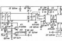
Before proceeding with the repair and adjustment of the module, it is necessary to familiarize yourself with the circuit diagram, and the location of the adjustment and adjustment elements.
1) with the TV turned off, remove the back wall of the TV and carry out a thorough external inspection, paying attention to any external, visually distinguishable defects in the installation of parts, the presence of radio elements with external damage (broken leads, swelling, darkened from overheating of the coating, touching each other elements). Installation should not have breaks and short circuits of conductive printed conductors;
2) with the TV turned on, make sure that the contacts in the connectors are reliable;
3) Measure the constant and pulse voltages at the contacts of the modules, at the terminals of transistors and microcircuits (from the printing side) and compare the obtained values with those given in the circuit diagram.
Elimination of violations of installation.
Installation violations include the elimination of breaks in leads, conductors, cold solder joints, short circuits of printed lines, breaks in bundled wires and connector contacts, as well as gluing conductive printed conductors. In case of small breaks in the printed lines (burning of the layer, cracks, etc.), it is possible to solder a single-core wire without insulation with a diameter of 0.5 ... 0.8 mm into the break area.
Read more…
Winter is coming soon. The main flow of cold comes from uninsulated windows. With the onset of the cool period of the year, each of us tries to insulate windows for the winter, especially if repairs in an apartment or house have been carried out for a long time. Below, the article discusses the main ways to insulate windows for the winter.
A selection of tips for troubleshooting problems in Vestel TV circuits will allow you to quickly and efficiently repair your sick TV.
TV Vestel() (different models, common chassis) the firmware flies: you cannot select the VHF & UHF bands in the menu, but S1-S10 (CATV) appears, plus the power switch sparks. I didn’t find how to switch in the service-manual, I took the firmware from a similar model and completely reflashed the microcircuit. There were 3-4 models with this malfunction.
Entering the service menu for TVs Vestel (Chassis 11AK19P) While in the menu, press in sequence: 4,7,2,5 Fits almost all Vestel models (who knows where they are assembled?), As well as Eldorado TV (the same, only the name has been changed).
VESTEL 7216 GST PIP Chassis 11AK19B-1 The horizontal transistor is on - check the TMS is a small transformer in the HOT base (output trans SR). All these Turkish chassis suffer from non-solders on the deflection coil connector and in general in the line scan area.
In TVs on the 11AK19 chassis (VESTEL, ELDORADO, etc.), a defect is often observed in the form of twitching and tearing of the image, and synchronization failure. This is due to poor contact of the HV wire in FBT 1142.5086 (poor design or execution). Eliminated by rigid fixation of this wire relative to the FBT case. In analog HR7950 this defect was never observed.
Vestel. TDA8842 + TDA6108 Fault: Bright screen illumination with LOH (reverse lines). After a few seconds, protection is activated and the TV goes into standby mode. The power supply of the video amplifier +200 is normal. There is no signal at the TDA6108 RGB inputs. One of the TDA6108 outputs turned out to be broken (short circuit to ground), while the TDA8842 blocks the outputs. TDA6108 can be replaced with TDA6107. Only in this case, it is necessary to additionally install 3 protective diodes at the outputs according to the TDA6107 wiring diagram.
VESTEL 72cm (chassis 11AK37) Large horizontal size, vertical lines are concave along the edges (correction does not work). The reason is a broken coil L603. It was possible to restore, because. the break was near the exit.
Vestel 2151 Fault: when turned on from the duty room, it "tsikal". The test showed an underestimation of the output voltages from the UPS in operating mode. The zener diode TL431 turned out to be faulty.
Vestel VR2106TS chassis 11AK-30 Narrow vertical band - check R645 2k2 , C627 430n250v capacitor replacement.
Vestel VR74STF Chassis 11AK37 processor ST 92195C381 / OEO The TV starts, but there is almost no image and there is simply no other sound in the BG standard, it does not remember the settings - the memory 24C08 is killed - after replacing the clean memory, I set all the options manually in service mode (from another TV). Entering the TUITANIUM-210 service menu: on the remote control, the "M" button is the main menu, then buttons 4,7,2,5 and options:
OSD 050 ; IF1004; IF2 077 ; IF3003; IF4062; AGC037; VLIN 007 ; RGB 007 ; VSOF -03 ; VPOF -01 ; HSOF -01 ; HPOF -08 ; HTOF -01 ; WR025 ; WG025 ; BB 025 ; BR030; BG030 ; APR 004 ; FMP1 011 ; NIP1 028 ; SCP1011; SEC1 081 ; FMP2013 ; NIP2 045 ; SCP2008; SEC2049; F1H 00001011 ; F1L 01010010 ; F2H 00011101 ; F2L 00000010 ; BS1 00000001 ;
BS2 00000010; BS3 00001000; CB 10001110; OP1 11101101; OP2 00011001; OP3 11101101;
OP4 01111111; OP5 11110011; TX1 01011110; GEOM 00101100; OP8 00000000 . If you press the green button, then enter the submenu for setting the geometry: VSIZ 031; VPOS 019; VSCO 003; VCCO 007; HSIZ 008; HPOS 034; HPIN 011; HCCO 013; HTRP 014; VZSZ 006.
The exit from the menu is also the "M" button on the remote control. This is all on a diagonal of 74 cm with a flat screen. ATTENTION! Before changing the settings, they must first be overwritten.
Vestel VR54TF chassis 11AK30A11 processor ST92195C3B1 / OEO VESTEL / T3X210 The power supply does not start, Q801 P6NK60ZF and R836 burned out (there is a jumper in the earlier chassis instead of R836) after replacing the burnt parts and turning on the TV, Q801 and R836 burned out again, after a thorough check, the chip turned out to be faulty IC800 MC44608 and again, when replacing ALL burnt parts, the TV worked fine. If Q801 has a short circuit on all pins, feel free to change IC800 MC44608 the simplest check of this mikruhi between 4 and 5 legs should be about 33 k, if 0 then it needs to be changed.
Vestel VR74STS-2915 Fault: the raster is strongly stretched horizontally. The correction is not adjustable. Breakdown D606 UF5407 in a diode modulator. After replacement, the correction does not work. Q602 9NQ20T also turned out to be faulty. Detected only by replacement. The transistor is not broken, you can open and close the source-drain, but it does not work in correction circuits.
VESTEL VR 54TFF-2115 periodically and not every day, on some programs, the sound began to grunt. It was treated by flashing the memory for the 11AK30 chassis.
VESTEL VR 54TF-2145 is not tuned to a cable channel in the range of 150-160 mHz. An attempt to rearrange the TUNER options to SERVICE from a nearby TV resulted in the loss of the VL range. Flashing many firmwares from 11AK30 did not help restore the range. Turning to the Service manual, I installed the options of one of the six possible TUNERs for this chassis, Alps TEDE9-004A which came up under the TUNER TAEM-G804D installed in the TV.
VESTEL-2151T. Chassis 11AK19-5(OOO>TELEBALT>) Fault: there is sound, there is no visible raster. As the accelerating voltage increases, a blue raster appears with retrace lines. I started with the firmware, it did not help (I put the memory on the socket). This AK19 chassis turns on even without MXS memory, there is a normal raster with noise. If, at the same time, a microcircuit is inserted into the panel directly on the working TV, then everything works. There is an image, sound, settings work. You turn it off to the duty one, then back to the worker and again it does not work. The reason is a malfunction of the ABB.<Подсажен>5 pin TDA6108J (ABB output was 20 ohms in one direction), there is also a 6.2 volt zener diode leak.
VESTEL 2151 Fault: the line transistor is heating up and flying. In the authorized center of Tambov, they stubbornly changed four times, although, according to the client, he did not work even two hours. The reason is the pre-output stage, replace the STX112. C607 10.0x50v failure is also possible.
V estel (chassis 11AK30) Fault: The output voltages from the power supply unit (UPS) are too low. Faulty D802 (BA159). After replacement, the DR indication LED lights up green, after a second, red, and so it repeats. Replaced IC801(SFH617A).
Vestel VR37TS-1445: Does not turn on from standby mode. The video processor STV2246H gets very hot. Replacing the video processor. Replaced by STV2249H.
West 21E11. Fault: no picture and no sound. Check and, if necessary, replace VD854 (open).
VESTEL chassis 11AK28/41/52/53 and the like, where there is a personnel STV9379FA or TDA8177F. Malfunction: there are such cases when it cuts off the neck of the kinescope. The fact is that the Turkish developers did not take care that when one of the supply voltages to the frame scan disappears, the TV goes into protection. And so one resistor breaks, the beam wraps and you're done. What should I do to prevent this from happening in the future, and how do I deal with it.
If the TV starts up, but does not light up in 10 seconds, I immediately turn it off (25-30 seconds are enough to cut the neck, verified by my own experience). I check and solder all the wiring and vertical scan power circuits (including SMD). I throw them away and put my resistors and electrolytes to power the MS (even if they ring like workers). Resistors of 0.22 Ohm at 3W. in both channels - not interrupted, the manufacturer puts 0.22-0.68 per 0.5W. and 1.2-2.2 Ohm at 1-2W. Electrolytes they put 1000mFx16v, and this is when powered by 14 volts per channel! And what firms!
Vestel Chassis11AK33 Fault: after the start, he goes into the duty room. Neither a careful visual inspection, nor a thorough check of all hot elements (memory, processor, IP, SR, CR) gave anything. The output correction transistor is intact (if it has flown off, everything is clear), the open resistor is normal, the inductor - well, as from a showcase. In short, I pulled this throttle, and on the LC meter. And there are short turns. When disassembling the inductor, the turns turned out to be fried at the beginning of the winding (not visually visible). The throttle was successfully disassembled and rewound. The telly worked. Conclusion: Turkish-Chinese quality of winding products. By the way, to check the throttle, if there are no devices, you can substitute DRT 1-1 from 3USCT for a while. If BDX53BFI flew off and there is no native one, then you can put BUT11, BUT12 or BUX84 - they work without problems. If the correction is assembled on a field effect transistor, then instead of BUK444 you can put 6N60, 6N80 and even BUZ90. P/S. The defect is typical, inherent in all VESTELs on 11AK:.
Vestel 5165. Chassis 11AK30. the standby indicator is on, the TV does not go into operating mode. The secondary voltages of the power supply are significantly underestimated. Troubleshooting led to the capacitor C827 - 4700.0x16V. After replacing it, everything worked fine.
When repairing various electronic equipment, the primary task is fault detection . Often, the search for the cause of failure of a device takes much more time than its elimination.
This article offers a certain troubleshooting technique for modern TVs. When there are situations that the TV does not show any signs of life, I try to adhere to this particular method of detecting a breakdown.
So where should you start.
To begin with, after "opening" the device, you need to clean its "inside" from dust. You can use a small brush and a vacuum cleaner, or you can do it in a different way, the main thing is the result.
After cleaning, you need to carefully inspect the board for defects in radio components that are visible to the eye (swollen capacitors, blackened resistors and resistances, microcircuits or transistors literally punched and burnt tracks). You should also pay attention to the “cannon” of the kinescope: if it is transparent, then everything is fine, if it is milky white, then the kinescope is faulty (there is a vacuum). If you cannot visually detect a malfunction, then check the TV's power cable and protective fuse. You should also check the network button to turn on the TV.
If the fuse is blown, then do not rush to change it and turn on the device, as it can burn from a short circuit in the power circuit and a faulty PTC (read how to change the PTC).
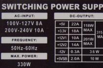
Then we move on to checking the power supply. To do this, you need to turn off the load, namely the line-scan output stage, and instead of it we connect a 220V and 60 ... 100W lamp. Depending on the size of the kinescope, the horizontal scan supply voltage (SR) varies from 110 to 150 V. We find the SR power filter capacitor in the secondary circuits (usually it has a rating of 47 ... incandescent lamp, simulating the load. To turn off the load, after this capacitor we find a choke, a limiting resistor or a fuse (sometimes just a jumper), through which power is supplied to the CP cascade and soldered off.
Due to a malfunction of the strapping elements in the power supply unit (PSU), when turned on, the key transistor or PSU chip may fail. To prevent this from happening, the PSU must be turned on through another 220V 100 ... 150W lamp, which will serve as a fuse. If, when turned on, this lamp burns brightly, then you should check the input circuits, the rectifier (diode bridge), the network, the power capacitor and the key element of the PSU (transistor or microcircuit). And if the lamp lights up and goes out or begins to glow weakly, then most likely the power supply is normal and then you need to disconnect this lamp and perform further diagnostics without it.
Now turn on the PSU and measure the voltage at the load: if the kinescope is 20 ... 21 inches, the voltage should be 110 ... 130V, if the kinescope diagonal is 25 ... 29 inches, then 130 ... 150V.
If these values are exceeded, it is necessary to check the elements in the primary power supply circuit and the feedback circuit. You should also pay attention to electrolytic capacitors, the capacity of which decreases when dried, and this leads to unstable operation and increased voltages.
At low voltages, you need to check the secondary circuits for short circuits and large leaks. You also need to check the protective diodes in the power supply of the SR, if any (usually R2K, R2M or similar). You should also check the protective diodes in the vertical scan power supply circuit (CR).
After making sure that the PSU is working, we remove the lamp that was used instead of the load, and solder back the element that was soldered to turn off the SR, thereby restoring the power supply circuit of the SR.
Line scanning
To check the SR, it is advisable to re-install the incandescent lamp as a fuse. If, when turned on, the lamp lights up and goes out or glows faintly, then the output stage of the CP is working. If the lamp lights up and continues to shine brightly, check the health of the output transistor CP. With a working transistor and the absence of high voltage, you need to check for the presence of control pulses on the basis of this transistor. If the voltages and impulses are normal, then the next step will be.
There is another breakdown of the SR, due to which the PSU does not turn on, and the lamp that is turned on instead of the fuse glows brightly - this is a malfunction of the horizontal deflection coils (breakdown). If these coils are disconnected and after that the TV turns on, then the deflecting system (OS) is faulty.
Personnel scan
The vertical scan (CR) check should begin with a measurement of the supply voltage, which, in most cases, is taken from the winding of the horizontal transformer. First of all, you need to check the limiting resistor through which power is supplied. Also, the rectifier diode in the power supply circuit of the CD and, in fact, the personnel microcircuit itself often fail. Very, very rarely there is an inter-turn short circuit in personnel deflecting coils. Checking these coils is best done by replacement.
kinescope power
If the power supplies and scans are working, and the TV screen does not light up, then, first of all, you need to check the power supply for the incandescence of the kinescope - it should be within 6 ... 8V. If voltage is supplied, check the integrity of the kinescope filament.
Tip: if there is a break in the filament winding in the TDKS, you can wind a new winding on the core of the same transformer - 3 ... 6 turns of MGTF 0.14 wire.
Color block, video amplifier, radio channel
If the scan is working and the screen is glowing, but there is no image, it is possible to determine the malfunction of one or another block by some signs:
The absence of image and sound indicates a malfunction of the radio channel - the video processor and tuner.
The absence of an image, but the presence of sound indicates a breakdown in the color block or video amplifier.
If there is an image, but no sound, you need to check the ULF or video processor.
Control block
It should be said right away that when repairing a control unit (CU), it is desirable to have the necessary data on the control processor (circuit, datasheet), which can be found on the Internet.
Signs indicating a malfunction of the control unit: the TV does not turn on, does not respond to the control buttons and the remote control, the volume, brightness, contrast and other parameters are not adjusted, channels are not configured or saved.
If the TV is not turned on, you need to check the power to the control processor and the operation of the clock generator (TG). Next, you need to find out if the signal from the processor goes to the switching circuit (indicated on the processor as “power” or “stand-by”): if the signal arrives, we look for a malfunction in the switching circuit; if not, change the processor.
If the TV does not respond to the remote control, you should. If it is working, you need to check the signal path from the photodetector to the processor. If a signal arrives at the input of the processor, and there are no changes at the output, then most likely the processor is faulty.
The same test principle applies to the control buttons on the TV panel.
All this, of course, is only a small part of the malfunctions that can be on TVs, but if, at one time, I had such an instruction for finding faulty blocks, it would have made it much easier for me to start working as a master.
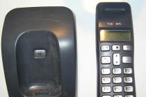
Hi all. Today we will repair the TV ST TV2106, which does not turn on.
TV model
After applying voltage, the red LED on the TV starts blinking and a squeak is heard. I will say right away that I will find a malfunction, but it will not work to repair the TV, but more on that later in the article.
Disassembly, cleaning of the board and initial diagnostics
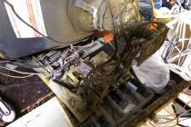
After removing the back cover, the first thing I decided to do was to clean the board from dust.

The state of the board after removing the back cover
It can be seen that the TV is assembled on a standard Chinese chassis, the repair of which is usually not very difficult. In order to simplify the work a little, I decided to clean the board from dust. For this, I used a paint brush and a vacuum cleaner.

Pay after cleaning
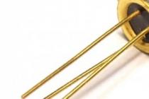
Since a squeak is heard after switching on, the culprit of this behavior is a short circuit in the output circuits of the power supply. In most cases, this is a burnt line transistor. A rocky transistor. I decided to check it for a short circuit. My suspicions were confirmed, since the horizontal transistor was completely shorted.

Checking the line transistor. The transistor is shorted, the multimeter in continuity mode shows a voltage drop of 0.003 V

To exclude a short circuit on the side of the board, the transistor rang again in a soldered state
Complete TV diagnostic and troubleshooting process.
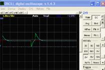
After removing the faulty transistor from the board, I decided to apply voltage to the board. The result pleased, since all the output voltages appeared, in particular, the power supply to the horizontal scan was 111.6 volts.

Horizontal power supply voltage
For such TVs, this voltage is normal.
To find out the true cause of the horizontal scan failure, for myself I use the following sequence of actions:
- First of all, I check the collector capacity for serviceability. Finding her is easy. Usually, this is a film capacitor with a rating of 6 nanofarads to 20 nanofarads, and a voltage of 1600-1800 volts. This capacitor is connected with one foot to the collector of the horizontal transistor (the central leg of the transistor), and the second to the minus.
- If everything is fine with the capacitor, then the deflecting system (hereinafter referred to as the OS) falls under the test next. TVs with a faulty deflecting system come across very often. Over time, the varnish on the OS wires is damaged, after which a short circuit is formed.
- The last thing I check is TDKS.
To protect the horizontal scan, I dropped the jumper from the power supply to the TDKS, and soldered a 60 W incandescent lamp instead. This lamp will protect the horizontal transistor in case of incorrect horizontal scanning.

To install a protective lamp, I removed the jumper, and soldered an incandescent lamp instead
After installing the lamp, I began checking the capacitor in the collector circuit. It turned out to be a 1800 volt 912j capacitor. Its value should correspond to 9 nanofarads. Connecting this capacitor to a multimeter, it showed 8.8 nF, which is within normal limits.

Checking the collector capacity
After checking the capacitor, I decided to solder the line transistor and turn on the TV. The lamp lit up brightly, which indicated that the line scan was not working properly, as there was a very large current consumption. In the normal state, the lamp should light up a little, or not burn at all. This is true for 14-21 inch TVs, for larger diagonal TVs, it is necessary to use a higher power lamp, since the current consumption in such TVs is much higher.

The glow of the incandescent lamp when the TV is turned on
If I had not installed the lamp, then the line transistor would immediately burn out.
The OS (rejection system) was next to be checked. To easily check it, you need to turn off your native OS, and instead throw some kind of osku from the disassembly.

OS connector
If you don’t know on the donor where the lower case coils are, where the personnel coils are, it doesn’t matter. We take a multimeter, and measure the resistance on the wires. Where the resistance is less (about 6 ohms), there we have line coils, where there are more personnel coils.
Searching in my bins, I found an OS to check.

OS from a donor for substitution
Previously, I disconnected the osci connector from the native board, and instead soldered the line coils of the donor OS. I did not solder the personnel coils, since we do not need them yet. After that, briefly turned on the board. The lamp glowed a little, then went out.

Soldered the donor OS to the board
I heard a high voltage, after which I turned off the board. The fact is that it is impossible to turn on the board without an OS for a long time, since there will be no magnetic field on the kinescope, and all the rays will hit at one point. The kinescope will show only one dot in the center of the screen. If you leave the TV in this position to work, then we get a burnout of the kinescope.

OS removal process. we unscrew these 2 bolts, after which we first remove the magnets, then the OS itself
After tearing off the old glue, and unscrewing 2 bolts, I did it. Throwing a new osku, and connecting it to the board, and removing the incandescent lamp, turned on the TV.

Turned on TV without connected frame coils. The spruce strip is visible, this is despite the fact that the accelerating voltage is wound up to 100%
The TV turned on, but the picture was so pale, with one of the colors missing. After checking the kinescope on the device, it turned out to be completely dead. Having phoned the owner, he confirmed that they ate the TV, and after discussing all the details, they came to the conclusion that it makes no sense to repair the TV.
Here is a repair. Although there is no working TV as a result, a malfunction was found. Here is a repair. If you have any questions, create topics on, I will be happy to answer. Thank you all for your attention, and see you soon in new repairs.