Often there is a need for remote control of a remote object, for example, control of heating, alarm system of a country house, etc. Traditional methods of management will not help here. In this case, cellular communication will come to the rescue. But simply taking a cell phone will not help matters, a DTMF code decoder is required, which, when a particular number is pressed on a cell phone, will switch one or another channel on the decoder. It is this decoder that is presented to your attention.
Main parameters of the decoder:
- has 10 independent control channels;
- password access;
- maintaining the state when the power is turned off;
- sound confirmation of events;
- automatic recording of the state of the outputs, if enabled;
- automatically lock the device if password access is enabled.
The decoder circuit is quite simple and does not need to be adjusted. All functionality is implemented on the microcontroller PIC16F883 .
As a decoder DTMF signal, a specialized microcircuit of the brand is used MT8870. At the output, buffer stages are installed on ULN2003, which allows the relay windings to be connected in series.
I assembled a trial version of the device on a breadboard
The circuit provides for the installation of three jumpers, their purpose:
- S1 - Enable saving the state of the outputs;
- S2 - Reset password;
- S3 - Enable password access.
The algorithm of the device is very simple:
We call the phone and by pressing the buttons on the phone we control the device. If jumper S3 is installed, a password must be entered before switching the state of the outputs (default 0000). Next, to turn on the required channel, press the channel number and number 1. To turn off - the number of the selected channel and number 0. For example, turn on and turn off channel number 5. Press 51, and then 50. If you want to turn on all channels at once, press two asterisks (* *). To turn off all channels at once - two gratings (##).
To change the code, enter the following combination: *#*# followed by four digits of the new code. If you have forgotten the entered code, it is easy to reset it to the standard 0000 by briefly setting jumper S2.
As a rule, in country houses cases of blackouts are not uncommon, and short-term disappearances during strong winds are also possible. To save the state of the outputs, it is possible to write the state to the non-volatile memory of the microcontroller and restore this state when the power supply is restored. For this, jumper S1 is used.
Chochu pay special attention to the pinout of the connector for connecting the device to a cell phone. Different manufacturers solder this connector in the phone in different ways! If the device does not respond, swap the leads, or look for a pinout specifically for your phone. The auto-up feature is available in almost any phone!
A small video review on working with the device
In some cases, it becomes necessary to remotely turn on and off any load, device, for example, control the lighting of a house to create the effect of the presence of residents, or turn on any device in advance.
Cell phone manages the load
At present, the cellular communication channel is the most convenient channel for remote control. Now there are many different devices built on microcontrollers and working via SMS, or made on specialized microcircuits that understand the commands of the phone buttons. But all this can be too complicated for a simple case when you only need to turn one load on and off. Such a device should consist of a cell phone and a trigger, with a relay output.
It should respond to a call signal. And there must be a delay at the input of the trigger. The fact is that advertising in the form of SMS messages periodically comes to any cell phone, while there is a short ringing signal. So, the delay is needed so that the trigger does not work on a short signal, but only on a significantly longer one that comes with an incoming call. Now the second question is how to connect the cell phone to the trigger? Very unregulated. If the duration of the display is more than the charging time of C1, then the voltage on C1 reaches a logical unit and the Schmitt trigger on the elements D1.3 and D1.4 switches.
If the duration of the display is less than the charging time of C1, then the voltage on C1 does not reach a logical unit and the Schmitt trigger on the elements D1.3 and D1.4 switches, and the capacitor itself is rapidly discharged through VD1 and R3. Now let's move on to the actual trigger that controls the relay. It is made on the D2 chip. This is a D-flip-flop, included according to the scheme of a single-digit counter. Its state is reversed each time an impulse arrives at its "C" input.
And so, at the moment the power is turned on, the trigger D2 is set to a single state by the RC circuit R7C2, which, at the moment the power is turned on, generates a pulse at its output 6. In a single state, the inverse output of the trigger, pin 2, will be a logical zero. Transistors VT1 and VT2 are closed, relay K1 is off. This is the original state. If now they called once and the duration of the call was sufficient to generate a pulse at the output D1.3, then the trigger D2 goes into the opposite state, a logical unit is set at its inverse output. The VT1-VT2 key opens and the K1 relay turns on the load with its contacts (not shown in the diagram).
When you call again (if the duration of the call was sufficient to generate a pulse at the output D1.3), the trigger D2 goes into its original state, zero is set at its inverse output. The key VT1-VT2 closes and relay K1 turns off the load with its contacts. A power supply with a voltage of 5 ... 6V, as such, you can use a charger for a cell phone, "figuring out" a tee. Or power the circuit from any other current source of the same voltage. Relay K1 with 5V winding. Installation can be performed on a breadboard printed circuit board, and clamps for fastening a cell phone that will work with it in pairs can also be provided on it.
Microcircuits can be replaced by foreign analogues (shown in the diagram). Chip D1 type K561LE5 is used here as a set of inverters, so it can be replaced by any other with at least four inverters, for example, K561LA7, K561LN2. The relay can be replaced by any with a 5V winding, suitable for the power of the contacts for switching a specific load. You can also use a relay with a winding for a higher voltage, but this will require a corresponding increase in the supply voltage. The supply voltage can be in the range from 5V to 15V. Naturally, if it is greater than the output voltage of the cell phone charger, the circuit will require a separate power supply.
Establishment comes down to setting the photosensor with resistor R1. It is necessary to cover the photoresistor with a cardboard box and adjust R1 so that the output of D1.2 is a logical zero. It is possible that you will have a photoresistor of a different type or nominal resistance, and it is quite possible that you will have to replace the resistor R1 with a resistor of a different resistance. Then, you need to put the photoresistor with a working surface on the cell phone display. Can be attached with clear tape.
Then cover this design with a cardboard box, and call a cell phone. In this case, its output D1.2 should be a logical unit. The next step is to adjust R5. First, set it to the maximum position. Then call this cell phone and "wait for an answer" until the D1.3 output is zero. If the call reset occurs earlier, reduce the resistance R5. Then, send SMS, D1.3 output zero should not appear, otherwise increase R5 a little.
The device (hereinafter referred to as the remote control) is designed for remote control of any device with a simple operation algorithm. Simply put - this is a remote switch (or switch) using a cell phone. In this case, the phone can be any, since the device is not connected to it galvanically.
Main technical characteristics:
- Supply voltage 12 volts
- Three possible modes of interaction with the control object
- turn on for 3 seconds
- turn on for 10 seconds
- shutdown for 10 seconds - Galvanic isolation from the controlled device
- Controlling the transition of the phone to receive mode
- Schema health monitoring
Schematic diagram of remote control:
Description of the scheme
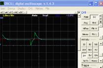
This circuit uses a phone operation sensor assembled on the elements L1, C1, R1, VT1, R2, which is the simplest electromagnetic field detector with low sensitivity. The operation of the phone in the receive mode on the oscillogram taken from the sensor is clearly visible.
The microcontroller works out the following algorithm when the phone receives a call: having received the first pulse, it goes into standby mode and after 15 seconds checks whether the pulse comes from the sensor again. If not, then it goes back to the beginning of the program, if there is an impulse, it turns on or off the relay for a given interval. Thus, some noise immunity and filtering of technological checks from the operator, as well as signals from SMS are achieved.

It may seem to you that protection against accidental operation is insufficient, but as practice has shown, this is more than enough. A remote computer worked with this scheme for about 3 years, which sometimes had to be restarted in this way. The computer was located on the other side of the city and worked in a technological room in a 9-storey building. It was not interesting to drive to restart it and spend a couple of hours on it, and restarting with the phone solved the problem in most cases. Of course, there are special devices for such cases, but, as practice shows, they cannot always solve the problem and are often not economically feasible. You can manage not only a computer - only imagination limits the options.
The relay operation time interval is set by switching SA2:
1. submission time log. 1 - 3 seconds
2. submission time log. 1 - 10 seconds
3. submission time log. 0 - 10 seconds
Switch SA1 simulates a triggered sensor. VD1 duplicates the pulses at the input of the microcontroller.
Used radioelements in the circuit. Interchangeability
Transistor VT1 can be mps9014, BC547. VT2 can be replaced by any medium power reverse conduction transistor. Select a 12 volt relay with contacts of sufficient power to control your device. Chip 78L05 can be replaced by 7805. Choke can use SMD.
The configuration bits are already written in the firmware file.
Device setup
Setting up the device comes down to flashing the controller and setting the sensor sensitivity level with resistor R1. It is enough that he would react to the phone from a distance of 3-5 cm.
The cost of parts to create such a device is about $3.
You can download the firmware and PCB file in LAY format below
List of radio elements
| Designation | Type | Denomination | Quantity | Note | Shop | My notepad |
|---|---|---|---|---|---|---|
| MK PIC 8-bit | PIC12F629 | 1 | To notepad | |||
| Linear Regulator | LM78L05 | 1 | To notepad | |||
| VT1 | Transistor | 2PC945 | 1 | To notepad | ||
| VT2 | Transistor | 2SC2682 | 1 | To notepad | ||
| VD2 | rectifier diode | 1N4001 | 1 | To notepad | ||
| C1, C2, C5 | Capacitor | 0.1uF | 3 | To notepad | ||
| C3 | 10uF 50V | 1 | To notepad | |||
| C4 | electrolytic capacitor | 10uF 16V | 1 | To notepad | ||
| R1 | Resistor | 330 kOhm | 1 | To notepad | ||
| R2 | Resistor | 6.8 kOhm | 1 | To notepad | ||
| R3, R5 | Resistor | 1.2 kOhm | 2 | To notepad | ||
| L1 | Inductor | 10 mH | 1 | To notepad | ||
| VD1 | Light-emitting diode | 1 | To notepad | |||
| K1 | Relay | 1 |
Remote control for 3 channels using
mobile phones "Siemens" and SMS messages.
The remote control system is designed for remote control of electrical circuits, for example: lighting in a country house or in the country house, turning on the electric watering of the garden, turning on the electric heating of the car engine in the winter in the garage, etc. and so on. The difference from the previous version is the connection to a mobile phone using the interface connector located at the bottom of the mobile phone.
D.W. consists of an electronic unit on a microcontroller that acts as an interface between a mobile phone and an actuating device, decoding incoming commands from the phone in the form of short SMS messages, which can be sent from any other phone.. At mobile phone is controlled by AT commands, you need to connect to the "Power" and "OK" buttons to turn on the power of the mobile phone. If you are sure that the phone will not turn off, these signals can not be connected. This remote control it is possible to connect to any of the Siemens phones listed on the diagram. It is also possible to work with other types of phones that have a communication port. The scheme of the device is shown in Fig.1. It is based on a microcontrollerPIC 16F 628A -I /Ptogether with the relay driver ULN2003A. The device is assembled on a single-sided printed circuit board.
Correctly assembled and from serviceable parts, the device does not need adjustment! It is only necessary to enter the user's mobile phone number to the D.U. data.
Work algorithm.
When the control unit is initially powered up, the controller determines whether the mobile phone is turned on by sending an AT command. If the controller does not receive a response within 7 attempts, it turns on the phone by successively pressing the "Power" key (holding it for 2..3 seconds, the time is programmed when the controller is flashed) and briefly pressing the "OK" key if the phone is already turned on, the procedure for turning on the mobile phone is skipped. Next, the mobile phone is initialized for its operation in the required mode of receiving SMS messages, which is indicated by flashes of the red LED "INIT", after which, if it is successfully completed, the green LED "OK" lights up, indicating the readiness of the D.U. to receive SMS commands and control. In response to the user's phone, a call is made. The user sees the call number and hangs up. This function was introduced at the request as an informational one, in case of power failure, if the system is not backed up by a battery.
Management is carried out as follows:
By sending a short "SMS" message to the mobile phone number to which the D.U controller is connected, with a certain text, part of which acts as a password, and part as a command. When such a command is received, the load is turned on or off, after which the incoming SMS is deleted from the phone, and in response to the user's phone, a ring is made.
The password is required for security purposes, so that there is no unauthorized control of the load channels.
No other text messages (including promotional ones) will cause D.W. to respond!
For example:
to turn on channel 1, send the following SMS text - "11 1234", where "1234" is the password, "11" is channel 1, 1 is turn on
to turn off channel 1, send the following SMS text - "10 1234", where "1234" is the password, "10" is channel 1, 0 is off. The default password is "1234", when flashing the controller, it is possible to set any password of 4 digits. (These commands are summarized in Table 1.)
After the channel is controlled, a control call will be made in response to the control phone, indicating that the command has been accepted. Thus, if you do not pick up the phone, the call will not be charged. When using tariff packages with minimal rates for SMS (or maybe even free of charge), there is no need to make calls, listen to the answers, whether the command was recognized (as was the case in the previously described D.U. using tone parcels), minimal financial costs are achieved!
Also in this D.W. There are two notification channels. Normal state - rebounds are enabled, i.e. they have voltage (this may be a signal about the presence of lighting, the heating boiler is turned on, from a security alarm, etc.). as soon as any of them disappears, a call is made to the mobile phone number specified during the firmware. The number of calls and the period of time can be changed when the controller is flashed. When the controller is operating, the "INIT" LED periodically flashes, indicating normal operation. LED "OK" - glows continuously. When an SMS command is received, it goes out, the command is executed, and then it lights up again, indicating that it is ready for execution next. commands.
Table 1.
Commands processed by the remote controller:
Team |
Name, appointment |
Team |
Name, appointment |
1 |
2 |
3 |
4 |
11 1234 10 1234 |
1 channel enable 1 channel turn off |
21 1234 20 1234 |
2 channel enable 2 channel turn off |
31 1234 30 1234 |
3 channel enable 3 channel turn off |
the command and password are separated from each other by one space, or an asterisk or any other icon you like, it does not play a role, but serves for visual separation. | |
Another option D.U. using SMS messages - the scheme is shown in Fig. 2. The main difference is that another controller is used, which sends confirmation messages about the actions taken with pre-prepared texts, as well as added command "00"+password not producing control, but only issuing a report on enabled/disabled channels. Also, you can control from any phone, which will receive response SMS, you do not need to enter this number into the controller's memory in advance! If necessary, it is possible to add control channels. The number is limited only by free controller ports! PCB drawing format SprintLayout v.4.0!

As a continuation, another construction by D.W. using SMS, only the security function is added - 2 (security inputs) when 12 volts appear on them. an alarm SMS is sent with a text of any content to the number (the text and the number are written to the firmware at the controller programming stage). Therefore, the meaning of the text may be different - depending on the security sensor, object, time of day, etc. This command-based design works similarly to the previous one - Fig. 2 The device operation is indicated by three LEDs:
Indication of device operation by 3 LEDs. LED1- indicates that the power is on, LED2 and LED3 - show the operation of the controller together with the mobile: The green LED blinks when the R.U. is in standby mode, i.e. switch S1 is not armed, when we close switch S1 - arm it, - the red LED blinks - the green one stops. The flashes are short - so as not to greatly discharge the battery if the power is not from the mains. If some security input is triggered, 12V power is applied. - then the red LED starts to burn with a steady light, does not blink. The corresponding SMS is being sent ... While the security input is in the "worked and did not return to normal" mode, re-sending and subsequent SMS will not be sent at this input until it is brought back to normal - as it returned to normal - the red LED goes out and this security the login will send SMS again if it works. This is done so that you do not receive a series of identical SMS for one event and do not waste money from your mobile account. While the first input is, as it were, blocked, i.e. sent one SMS - the second input works independently and similarly, i.e. if, after triggering and sending SMS on the first input, there will be an alarm event on the second one, it will also send its SMS and wait for it to return to normal.
Publication date - 25.02.2007
Last update - 07/05/2009
Yakimenko Sergey. Email: or or
The author accepts orders for the manufacture of devices for individual orders, and also sends programmed controllers complete with a printed circuit board for repeating published designs.
Publication in periodicals, as well as on other sites only with the written permission of the author!
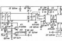
Schematic diagram of a set-top box for a cell phone for remote control and monitoring of the load status, not a complicated circuit on the KR1008Vzh18, K561LA7 microcircuits. There have already been several articles on the pages of the Radioconstructor magazine on the topic of remote control using a cell phone.
Usually, this is taken from a cell phone with an auto-answer mode. And from it the signal is fed through the headset to the DTMF decoder. Next up is the relay. With all the advantages, such a scheme also has an important drawback - it is not known what state the load is in, that is, it is on or off.
After all, we do not see what we control, and situations can be very different, for example, a power outage, or for another reason, the switched on load may not turn on or turn off if it is turned off.
circuit diagram
In this scheme, a solution to this problem is proposed - during the on state of the load, a repeating single-tone sound signal is applied to the microphone input of the cell phone headset, repeating at a frequency of about 0.3 Hz. That is, every three seconds. To determine the load is currently on or off, you need to call the object and listen. If there is a repetitive sound, the load is on; if it is not there, it is off.
The repetition period is chosen so large (3 seconds) that it is possible to give a command to turn off in the pause of the sound signal so that the sound does not interfere with the control. The device allows using a cell phone to control one load, switched on by an electromagnetic relay.
Rice. 1. Principal diagram of the set-top box for remote control and monitoring using a cell phone.
The diagram shows a standard headset with two earpieces, a microphone, and a button to control a cell phone. Now, most of the inexpensive cell phones come with just such headsets. When a headset is connected, the phone enters headset mode. When a call comes in, it vibrates, the display lights up, and a call tone is heard in the headphones.
You need to first transfer the phone to auto answer mode, this can be done in the settings for working with the headset, referred to in different phones - “car”, “hands free”, “auto answer”, “answer mode - automatically” or otherwise. In this mode, the phone itself will “pick up the phone” when any incoming call arrives.
Auto answer mode is available on most cell phones with wired headset jacks. However, there are those in which this mode is not available, despite the presence of a wired headset. This needs to be checked first. And so, an incoming call comes in, and the cell phone, being in auto-answer mode, “picks up the phone”.
After the incoming call is accepted, the DTMF decoder circuit on the D2 chip comes into operation. Since you will need to manage by pressing the buttons of the cell phone from which the call came. In this case, the tone code of these buttons will be transmitted, and through the headset it will go to the decoder on the D2 chip.
The RF signal is input to the D2 chip through C4-R4. The gain of the input ultrasonic microcircuit depends on the resistance of the resistor R4. When establishing, through trial and error, using this resistor, you need to set the optimal sensitivity of the D2 chip.
To give a command, you need to press one of the numeric buttons on your cell phone. In this case, to turn on relay K1, you need to press the button "1". To turn off - the button "2" (or another).
If a two-tone DTMF signal arrives at the input, the signal is decoded and as a result, a command binary code appears on pins 11-13. If the "1" button was pressed, then the unit will be at pin 11. A logical unit occurs, and the key on the transistor VT1 will open. Relay K1 included in its collector circuit with its contacts (not shown in the diagram) will turn on the load.
To indicate the on state, a repeating sound signal generator is assembled on the D1 chip. It consists of two multivibrators. The multivibrator on the logic elements D1.1 and D1.2 generates pulses with a frequency of about 0.3 Hz. These pulses are fed to pin 8 of element D1.3, which is part of the second multivibrator that generates pulses with a frequency of about 2.5 kHz.
When relay K1 is turned on, there is a logic one at pin 11 of D2. It goes to pin 2 D1.1 and starts the repeating sound signal generator. A repetitive sound signal through the resistor R3, which, when adjusted, sets the optimal signal level, is fed to the microphone input of the headset.
And the user hears a repeating beep as confirmation that the load is on. When the load is off, there is a logic zero at pin 11 D2. It goes to pin 2 D1.1 and turns off the repeating beep generator. And the user does not hear a repeated beep, which is a confirmation that the load is turned off.
Pin 10 of the D2 chip is connected to the positive of the power source, so after each command is received, the relay state will be maintained until the next command arrives. Relay type WJ118-1C or can be replaced by some other low-powered one with a winding of 12V and a winding resistance of at least 200 Ohms, and make contacts.
Myasnikov S. V. RK-2017-01.
Literature: 1. Myasnikov SV - The answering machine opens the gate. RK-7-2015.