“You can’t break the diet,” said the character of the famous cartoon. And he was right: health depends on the quality of food, and not only of a person. Our electronic friends need good food just as much as we do.
A fairly significant percentage of computer failures is related to power problems. When buying a PC, we are usually interested in how fast its processor is, how much memory it has, but we almost never try to find out if it has a good power supply. Is it any wonder then that powerful and productive hardware works somehow? Today we’ll talk about how to check the power supply of a stationary computer for operability and serviceability.
A bit of theory
The task of the power supply unit (PSU) of a personal computer is to convert the high AC voltage of the household electrical network into a low DC voltage that devices consume. According to the ATX standard, it has several voltage levels at the output: + 5V, +3.3V, +12V, -12V, +5VSB(standby - standby power).From the +5 V and + 3.3 V lines, USB ports, RAM modules, the bulk of microcircuits, part of the cooling system fans, expansion cards in PCI, PCI-E slots, etc. are powered. From the 12-volt line - the processor , video card, hard drive motors, optical drives, fans. From +5 V SB - logic circuit for starting the motherboard, USB, network controller (for the ability to turn on the computer using Wake-on-LAN). From -12 V - COM port.
The PSU also generates a signal Power_Good(or Power_OK), which informs the motherboard that the supply voltages are stabilized and work can begin. The high level of Power_Good is 3-5.5 V.
The values of output voltages for power supplies of any power are the same. The difference is in the levels of currents on each line. The product of currents and voltages is the power indicator of the feeder, which is indicated in its characteristics.
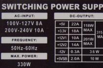
If you want to check whether your power supply matches the rating, you can calculate it yourself by comparing the data indicated in its passport (on a sticker on one of the sides) and those obtained during measurements.
Here is an example of what a passport might look like:

Working - not working
Probably, you have ever encountered a situation where nothing happens when you press the power button on the system unit. . One of the reasons for this is the lack of supply voltages.The power supply may not turn on in two cases: if it itself malfunctions and if the connected devices fail. If you do not know how the connected devices (load) can affect the feeder, I will explain: in the event of a short circuit in the load, the current consumption increases many times over. When this exceeds the capabilities of the PSU, it turns off - it goes into protection, because otherwise it will simply burn out.
Outwardly, both look the same, but determining which part of the problem is quite simple: you need to try to turn on the power supply separately from the motherboard. Since there are no buttons for this, let's do this:
- Disconnect the computer from the mains, remove the cover of the system unit and disconnect the ATX block from the board - the most stranded cable with a wide connector.

- Let's disconnect other devices from the PSU and connect a known-good load to it - without it, modern power supplies, as a rule, do not turn on. As a load, you can use an ordinary incandescent lamp or some energy-intensive device, for example, an optical disc drive. The last option is at your own peril and risk, since there is no guarantee that the device will not fail.
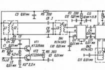
- Let's take an unbent metal clip or thin tweezers and close the contacts responsible for switching on the ATX block (which comes from the PSU). One of the pins is called PS_ON and corresponds to a single green wire. The second is COM or GND (ground), matches any black wire. The same contacts are closed when the power button on the system unit is pressed.
Here is how it is shown in the diagram:

If, after shorting PS_ON to the ground, the fan in the power supply starts spinning, and the device connected as a load also starts working, the feeder can be considered operational.
And what is the output?
Functionality does not always mean serviceability. The PSU may well turn on, but not produce the necessary voltages, not output the Power_Good signal to the board (or output too early), sag (reduce output voltages) under load, etc. To check this, you will need a special device - a voltmeter (or better, a multimeter ) with DC voltage measurement function.For example, like this:

Or any other. There are a lot of modifications of this device. They are freely sold in radio and electrical stores. For our purposes, the simplest and cheapest one is quite suitable.
Using a multimeter, we will measure the voltage at the connectors of a working power supply and compare the performance with the nominal ones.
Normally, the output voltage values \u200b\u200bunder any load (not exceeding the allowable for your PSU) should not deviate by more than 5%.
Measurement order
- We turn on the computer. The system unit must be assembled in the usual configuration, that is, it must contain all the equipment that you use constantly. Let's let the power supply warm up a little - we'll just work on the PC for about 20-30 minutes. This will increase the reliability of the indicators.
- Next, we launch the game or test application to load the system to the fullest. This will check if the feeder is able to provide energy to the devices when they are running at maximum consumption. You can use a stress test as a load powerSupply from the program.

- Turn on the multimeter. Set the switch to 20 V constant voltage (the constant voltage scale is marked with the letter V, next to which a straight line and a dotted line are drawn).

- We connect the red probe of the multimeter to any connector opposite the colored wire (red, yellow, orange). Black is the opposite of black. Or we fix it on any metal part on the board that is not energized (voltage measurement should be carried out relative to zero).

- We take readings from the display of the device. 12 V is supplied through the yellow wire, which means that the display should show a value equal to 12 V ± 5%. On red - 5 V, the indicator will be normal 5 V ± 5%. In orange, respectively - 3.3 V ± 5%.
Lower voltages on one or more lines indicate that the PSU is not pulling the load. This happens when its actual power does not meet the needs of the system due to component wear or poor workmanship. Or maybe due to the fact that it was initially incorrectly selected or ceased to cope with its task after upgrading the computer.
To correctly determine the required PSU power, it is convenient to use special calculator services. For example, . Here the user should select all the equipment installed on the PC from the lists and click " Calculate". The program will not only calculate the required feeder power, but also suggest 2-3 suitable models.

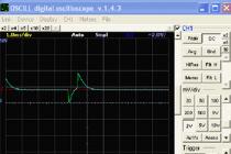
As a result of all conversions of the input AC voltage (rectification, smoothing, re-converting to an alternating frequency with a higher frequency, stepping down, another rectification and smoothing), the output must have a constant level, that is, its voltage should not change over time. When viewed with an oscilloscope, it should look like a straight line: the straighter, the better.
In reality, a perfectly flat straight line at the PSU output is something from the realm of fantasy. A normal indicator is the absence of amplitude fluctuations of more than 50 mV along the 5 V and 3.3 V lines, as well as 120 mV along the 12 V line. If they are larger, as, for example, in this oscillogram, the problems described above arise.

The causes of noise and ripple are usually a simplified circuit or low-quality elements of the output smoothing filter, which is usually found in cheap power supplies. And also in the old ones, which have developed their resource.
Unfortunately, it is extremely difficult to identify a defect without an oscilloscope. And this device, unlike a multimeter, is quite expensive and is not often needed on the farm, so you are unlikely to decide to buy it. Indirectly, the presence of ripples can be judged by the swing of the arrow or the running of numbers on the multimeter display when measuring constant voltages, but this will be noticeable only if the device is sensitive enough.
We can also measure the current
Since we have a multimeter, in addition to the rest, we can determine the currents that the feeder produces. After all, they are of decisive importance in calculating the power indicated in the characteristics.The lack of current also affects the operation of the computer extremely unfavorably. An “undernourished” system slows down mercilessly, while the power supply heats up like an iron, as it works at its limit. This cannot go on for a long time, and sooner or later such a PSU will fail.
The difficulty of measuring the current lies in the fact that the ammeter (in our case, a multimeter in ammeter mode) must be included in the open circuit, and not connected to the connectors. To do this, you will have to cut or unsolder the wire on the tested line.
For those who decide to experiment with measuring currents (and without serious reasons, this is probably not worth doing), I give instructions.
- Turn off your computer. Divide in half the conductor on the line under study. If it's a pity to spoil the wires, you can do it on an adapter, which is connected to the power supply connector at one end, and to the device with the other.
- Switch the multimeter to the mode of measuring direct currents (their scale on the device is indicated by the letter A with straight and dotted lines). Set the switch to the value exceeding rated current on the line (the latter, as you remember, is indicated on the PSU sticker).

- Connect the multimeter to the break in the wire. Place the red probe closer to the source so that the current flows in the direction from it to the black one. Turn on the computer and fix the indicator.
More on the site:
Eat to "live": how to check the power supply of a computer updated: March 8, 2017 by: Johnny Mnemonic
Since with power supplies, I see, I got involved a little seriously and apparently for a while (I would like to pick up and systematize the base of circuits, and understand a little about modern circuitry), and I just can’t get off with a couple of videos, I decided to simplify the task a little.
I'll start from the end, here's what happened. This is the first version without switching additional loads.
Since the nichrome wire finally arrived, I began to gradually make a block of load resistances for ATX power supplies. Testing with car bulbs is somehow not right, the fact is that when you connect or start with such a load, a current surge occurs. And there is a chance to burn, perhaps a newly repaired unit.
As a case, I took a case from an old ATX power supply.

To begin with, I decided to install a second fan so that they work together to blow through the spiral.

Accordingly, 12V, 5V, 3.3V loads. it will also be necessary to install three switches for switching loads. for all three circuits. You also need to set the load for -12V and +5V SB, obviously in the form of powerful resistors.
- М4-8/Ф8-50MM — 9 pcs
I carved the first rack, with an M4 thread, it turned out that the thread was rather weak, it was necessary to M5. Turned the second, fixed, keeps well. It does not short-circuit from below, but the nut will have to be lifted a little on plastic washers.

I made 8 more holders, all to a height of 50 mm
 Just inserted, not twisted
Now we need to make M3 in the holders. Each has three 2.5 mm holes, and cut the threads accordingly. This is done in the milling cutter, and you first need to go through centering. I also chamfer about 0.5 mm on both sides for better contact of the nichrome wire and better clamping with a washer / nut.

And then a drill. M3 suggests a 2.6mm hole, I use a 2.5mm drill.
 Installed all coils
Spirals 12v-2+1, 5v - 1+1, 3.3v - 1+1
Now it remains only to find the ATX connector, make a small adapter card, everything is gathered together.
To begin with, I made a template from an old broken motherboard
 Trying on
  We cut the tracks with proxon
  We attach it to the back panel. View from the inside.
 Soldered main loads 5/12/3.3 and closed pwr_on. I did not connect additional loads, since it is necessary to install a couple of switches.
  Here is the look
Next, you need to install an additional switch for 12 / 3.3 and 5V loads. Since short spirals are not connected yet. Also, loads for 5 duty and -12V are not installed. It will probably be a 24 and 33 ohm resistor, with a capacity of 1 and 5 watts.

I started the load, manually switched the loads, the + 12V coil heats up to red. It may even be necessary to use a larger diameter nichrome coil to increase its length and improve cooling.
UPD. Switched loads.
Main 140 W
- +5 ~15A
- +12 ~5A
- +3.3 ~5A
Additional on switch hung, red

- +5 - ~10A
- +3.3 - ~ 10A
And I planned to bring an additional 360 watts 12v / (10 + 20A) to another connector.
UPD. And here is how professionals test power supplies. Quite an interesting solution. Take a meter of a radiator profile, put more coolers on one side, and electronics on the other. I really liked the idea.
Modern power supplies, in general, and for a computer in particular, are quite complex devices. There are more than a dozen main electrical characteristics alone, and there are also noise, thermal, weight and size characteristics. All power supplies of the ATX standard are pulse converters with different variations of circuit solutions, but with a single principle of operation. Without special equipment, in the form of controlled loads, an oscilloscope and some other devices, it is impossible to test compliance with the standard of the characteristics indicated on the sticker and in the power supply passport. The simplest question is "Will the power supply XXX be enough to run the UUU computer?" actually not so simple at all. To answer this question, you need to familiarize yourself with the various characteristics of existing power supplies and the typical consumption of computer hardware.
Power supply specifications
All the main characteristics and requirements are described to some extent in documents known as ATX12V Power Supply Design Guide Version 2.2, SSI EPS12V Power Supply Design Guide Version 2.91 and similar. This documentation is intended for power supply manufacturers to ensure that their hardware is compatible with the generally accepted ATX standard. This includes the geometric, mechanical and, of course, the electrical characteristics of the devices. All documentation is available in open form on the Internet (ATX12V PSDG/SSI EPS PSDG). Here are the main topics covered in this documentation. It’s worth starting with the most important value, which is indicated on every power supply available at retail.
Permissible load power
Each power supply has several output channels with different voltages and is designed for a certain long-term power for each of them. The modern standard prescribes the presence of channels with a voltage of + 5V, + 12V, + 3.3V, -12V and a standby voltage of + 5V. The total power is usually indicated in watts on the sticker (in English it sounds like Total Power). This value is the sum of all the powers for each of the channels and is easily calculated by summing the product of the currents and the corresponding voltages. For example, we have a power supply with a power of 500 watts, with the indicated permissible currents: + 3.3V 30A, + 5V 30A, + 12V 40A, -12V 0.8A, + 5Vd 2.5A. Multiplying and summing up, we get the final figure (250 + 480 + 9.6 + 12.5) = 752.1 watts. Why does the label say 500W? The fact is that there is a mutual dependence of the channels of their joint maximum power. The sticker states that the maximum power on the +3.3V and +5V channels cannot exceed 152W in any case, and the total combined power of the +12V and +3.3 & 5V channels must not exceed 480W. That is, we can load the unit at full power at +12V, leaving the low-voltage channels unloaded, or at full power of the +3.3 and +5V channels (152 W in our case), we can use only 328 W at + 12V. Therefore, when calculating, you need to be careful and always pay attention to the permissible load combination for each line. This is usually indicated on a sticker, in the form of a common cell with a single power value for several channels.

Taking this factor into account, the new power recalculation will look like this: 152+328+9.6+12.5=502.1 W, or 0+480+9.6+12.5=502.1 W, or any of the allowable variations between these two extreme values of power distribution by channels. Based on this, the question arises - how to test the unit: at full load through low-voltage channels, or at the maximum channel power + 12V? Or maybe some intermediate value? Let's consider this point in more detail later.
Also, do not confuse the parameters of maximum long-term power and peak power (Total Peak Power), permissible for a short period of time (17 seconds according to ATX 2.2 and 12 seconds according to EPS 2.91). For example, a power supply with a rated power of 500W can deliver up to 530W at a peak, but it is undesirable for a power supply to constantly work in excess of the rated power, because the margin of safety of the components may not be very large, and unpleasant fireworks will happen in a hot summer.
Permissible voltage deviation level
This characteristic is one of the main ones and determines the permissible deviation of each of the voltages. It will be more convenient and clearer to present these values as two tables taken from the EPS 2.91 standard:

Table 20 reflects the maximum allowable deviation level, and table 21 is optional, with more stringent limits that are relevant for graphic stations and servers. If the voltage deviation is below 5-10% of the threshold, it is likely that the computer will malfunction, or spontaneous reboots during a heavy load on the processor or video card. Too high voltage negatively affects the thermal operation of converters on the motherboard and expansion cards, and can also damage sensitive hard drive circuits or cause them to wear out. In the more loyal ATX Power Supply Design Guide, in addition to channels with a voltage of + 12V, a permissible 10% deviation is regulated at peak load on these channels. In this case, the voltage of the +12V2 channel (usually used to power the processor) should not drop below +11 V.
Ripple level
No less important is the minimum possible voltage surges (ripples) on each of the lines. Permissible frames are described in the standard as mandatory and look like this:

The sources of ripples are usually converter circuits inside the power supply itself, as well as powerful consumers with a pulsed nature of consumption, such as processors, video cards. Hard drives and the block of magnetic heads present in them during frequent movement can also create bursts of interference, but their power is much less.
Input voltage, efficiency and PFC
The power supply must operate in all permissible modes at the following input voltages:

The presence of the voltages shown in the table below must not cause damage to the power supply circuitry. Loss of mains voltage for any period of time, at any time of operation, should also not lead to a malfunction of the unit. When turned on, the charging current of the high voltage capacitors must not exceed the ratings of the input circuits (fuse, rectifier diodes and current limiting circuits).
There is a myth that a more powerful power supply consumes more power from the outlet, compared to a low-powered cheap counterpart. In fact, the opposite is often the case in reality. Each block has energy losses when the mains voltage is converted to low-voltage DC, which goes to the computer components. The efficiency (efficiency) of a modern cheap unit usually fluctuates around 65-70%, while more expensive models can provide up to 85% efficiency. For example, by connecting both units to a load of 200 W (which is approximately what most computers consume), we will get a loss of 70 W in the first case and only 30 W in the second. Saving 40 watts when running your computer 5 hours a day and a 30-day month will save 6 kW on your energy bill. Of course, this is a meager figure for one PC, but if we take an office with 100 computers, then the figure may turn out to be noticeable. It is also worth considering that the conversion efficiency is different for different load power. And since the peak efficiency falls on 50-70% of the load range, there is no practical point in purchasing a power supply unit with a double or more power reserve.
The operating efficiency should exceed 70% for full load, and 65% for 20% load. At the same time, the recommended efficiency is at least 75% or better. There is a voluntary certification system for manufacturers known as Plus 80. All power supplies participating in this program have over 80% conversion efficiency. Currently, the list of participating manufacturers in the Plus 80 initiative includes more than 60 items.
Also, do not confuse the efficiency of the power supply with such a characteristic as the power factor (Power Factor). There is reactive power and active power, and the power factor reflects the ratio of reactive power to the total total power consumption. Most power supplies without any correction circuits have 0.6-0.65 power factor. Therefore, switching power supplies generate reactive power to a large extent, and their consumption looks like powerful pulses during the peaks of the mains sine wave. This creates interference on the mains that may affect other devices powered by the same mains. To eliminate this feature, schemes with passive power factor correction (Passive PFC) and active (Active PFC) are used. Active PFC effectively copes with this task, in fact, being a converter between the power supply itself and the mains. The power factor in blocks using APFC easily reaches 0.97-0.99, which means the almost complete absence of a reactive component in the power supply consumption. The passive Power Factor correction circuit is a massive inductor connected in series with the mains wires of the power supply. However, it is much less effective and in practice increases the factor to 0.7-0.75. From the point of view of the computer and the consumer, there is practically no difference between a block with APFC and a block without correction at all, the use of the former is beneficial for power supply companies.
PSON and PWOK signal lines
PSON (Power Supply ON) - a special signal line for turning on / off the power supply by the logic of the motherboard. When this signal is not connected to ground, the power supply must remain off, except for the +5V (standby) channel. At a logic zero (voltage below 1 V) - the logic turns on the power supply. PWOK (Power OK) - a signal line through which the power supply informs the motherboard that all output lines are in a normal state and stabilization is carried out within the limits specified by the standard. The delay time for the appearance of a signal during normal operation of the power supply from the moment a logical zero is applied via PSON is 900 ms.
Protection schemes
The power supply must have protection circuits that will turn off the main outputs in case of abnormal situations. The protection must block the restart until the turn-on signal reappears on the PSON wire. Overcurrent protection (OCP) is mandatory for lines +3.3, +5, +12, -12, +5 (on duty), the minimum threshold is 110%, the maximum is 150%. In case of overload, the unit must turn off and not turn on until the turn-on signal appears, or until the mains voltage is completely de-energized. Over Voltage Protection (OVP) is also required and must be monitored within the power supply itself. The voltage must never exceed those specified in Table 29 at any time.

Over Temperature Protection (OTP) for power supplies is not a mandatory feature, so it is important to comply with the operating conditions of power supplies in cramped enclosures or in places with poor ventilation. The maximum air temperature during operation should not exceed +50°C. Some manufacturers calculate and indicate the power of the power supply at a low temperature of +25, or even +15 ° C, and an attempt to load such a product with the specified power in hot weather can lead to an unpleasant ending. This is exactly the case when the note sixth from the bottom matters. If it is possible to find an acceptable temperature range for a particular block model on tests, we indicate this explicitly in the table with characteristics.
Short-circuit protection (Short Curcuit Protection, SCP) - is mandatory for all power supplies, is checked by briefly connecting the power bus between the channels and the ground of the power supply.
A little about the division of the + 12V channel into several "virtual"
The hackneyed separation of channels is caused by the requirement of the EN60950 safety standard, which prescribes to limit the current on the contacts accessible to the user at the level of 240 VA. Since the total total power of the + 12V channel in powerful power supplies can exceed this value, it was decided to introduce a division into several separate channels with individual current protection of less than 20A. These separate channels are not at all required to have individual stabilization inside the PSU. Therefore, in fact, almost all power supplies have one high-current + 12V channel, regardless of the number of virtual channels. Although there are several models on the market with truly separate regulators and several independent +12V lines, this is only an exception to the general rule. For computer components, virtual, as well as real, division into channels does not affect in any way, and those of the components that may require a current of more than 18-20A have the ability to connect two separated channels. So the 8-pin power connector of the processor on motherboards has two pins for each of the two channels, and the top NVIDIA and AMD video cards have two 6-pin ones (or a combination of 6-pin and 8-pin, like the Radeon 2900 XT, Radeon HD 3870 X2, GeForce 9800 GX2) connector.
In addition to electrical characteristics, there are also physical ones. Each block claiming to conform to the ATX form factor must be 150mm wide by 86mm high. The depth of the block can vary from 140mm to 230mm or more.
Cable equipment of the block
Existing power supplies are equipped with a mass of cables with different types of connectors. Information about their lengths and quantity will allow you to determine even before purchase whether a particular model is suitable for the desired case, or you will have to buy additional adapters and extension cords. All these parameters are displayed in the form of a table for each of the tested blocks. The upper part is fixed cables, and below, in the case of detachable wires, the number and length of all cables with connectors are indented.

If there are several connectors on one wire, the lengths to each are written in a row. For example, the total cable length in the example above for the last SATA connector is 45+15+15 = 75cm. Non-standard connectors, for example, a 3-pin fan speed monitoring cable, or adapters are indicated in the bottom rows of the table. In addition to listing the cables and their types, the thickness of the wires used in the cables is determined, the presence of additional wires for monitoring and compensating the resistance of the wires to the connector (the so-called Vsense wires).
Noise of the cooling system
Almost all power supplies are equipped with a fan to actively cool the components inside the case. In addition, the fan also pushes the heated air inside the computer case out into the environment. Most modern power supplies have a 120 mm fan located on the bottom wall. Increasingly, models with a 135 or even 140 mm fan are becoming more common, so that noise levels can be reduced while maintaining cooling efficiency. However, in older powerful models, an 80 mm fan is still used in the rear end wall, which ejects air from the PSU to the outside. Variations are also possible using a different location of the fan, or the use of several fans. Almost all units are equipped with a dynamic fan speed control circuit, depending on the temperature inside the PSU (most often the temperature of a heatsink with stabilizer diodes).
Power consumed by various components
The largest share of power consumption is accounted for by the central processor and video cards. There are many different computer consumption calculators on the Internet. Gives fairly reliable results. Our test system based on an Intel Xeon 3050 processor, an Intel DP35DP motherboard, four DDR2 memory modules, an NVIDIA GeForce 6600GT video card, and three Seagate ST3320620AS hard drives, according to the calculator's calculations, requires a 244W power supply. The measured real consumption of the system under load reached 205 watts. The figures are similar, and the presence of some power reserve will not hurt, because the PC configuration may change over time, for example, another hard drive will be added, or the video card will be replaced with a more productive one. It will be unpleasant to change the power supply with each such replacement. Modern 4-core processors based on 65nm Intel and AMD cores require up to 100-140W of power (without overclocking), and the 45nm Intel Core 2 Extreme QX9650 is content with 75-80W at full load. The older NVIDIA and ATI video cards are much more voracious, and a tandem of two GeForce 8800 Ultra or ATI Radeon HD 3870 X2 video cards can require up to 350-450 W for the graphics subsystem alone. In such configurations, it is logical and necessary to use the appropriate power supplies, with a power of 500-600W. The remaining components consume little, one hard drive barely reaches the mark of 15-25W during the start and positioning of the heads, the memory module requires an average of 4-10W, peripheral boards - 5-25W. Cooling systems, with the exception of complexes using thermoelectric elements, also consume a little: 10-40W.
Methodology and test stand
Now it’s a little clear that for a full-fledged testing of the power supply, it’s not enough just to measure the voltage at the outputs with a voltmeter. This can only show the absence of obvious and serious problems in the operation of the power supply, but nothing more. The main problem in providing quality power usually lies in the inability of the power supply to deliver the required current for each component of the computer, or excessive voltage deviation from the nominal value. All sorts of variations of testing by the “voltmeter method” can only show that the computer is able to work on a specific load, at a specific point in time, but it absolutely does not show how much power the power supply can actually produce, and does not show what will happen to the power supply, if the load exceeds the allowable power.
To test and find out the technical characteristics of each power supply unit, it is connected to a special stand, which allows you to simultaneously measure the voltage and current levels on all output channels in automatic mode. Before testing at the stand, all power supplies are disassembled, photographed, the quality of soldering and installation is checked, the components on the boards are inspected for defects. If available, they are described in the article, with reference to the fact that one particular unit may be defective, like any other complex electronic equipment. Also, there is always a photograph of the sticker of the power supply, with permissible power values for all channels. If the mounting density allows, a review of the applied element base and features of schematic solutions is carried out. Often there is a situation when companies do not develop themselves, but only sell third-party power supplies from OEM companies. This can usually be identified by the UL certification code, which is rarely hidden and is printed on the main specification label, and looks like “E123456”. An example of using this principle is OCZ, Tagan, ThermalTake and others. You can determine whether the code belongs to the manufacturer's name on the UL Online Certifications Directory website by searching for the code from the sticker in the UL File Number column.

For boxed products, the equipment and additional accessories are reviewed. At the same stage, data on the power of the unit and channels from the sticker of the power supply are entered into the stand control program, and all the necessary connectors are connected, in accordance with the distribution of channels. The operation of the short-circuit protection circuits (each line is connected in series to the earth bus) is checked, as well as the overload protection on the channels. The block for measuring the input parameters of the network is currently under development, therefore, measurements of efficiency, power factor and PSU operation with a different range of input voltages are temporarily not carried out. After carrying out a basic check of the functioning of the power supply, the graphs of the cross-load characteristic (CNC) are taken. Usually, to stabilize the voltages + 12V and + 5V in power supplies, a group switching circuit is used, which equalizes the arithmetic mean between these two voltages. Such a device is easily seen when viewing the internal structure of the power supply; for a group stabilizer, one inductor of a larger and one smaller diameter is used for the + 3.3V channel, which is stabilized separately. These chokes are usually located near the connection point of the wires of the output channels of the power supply.

The disadvantage of such a switching circuit is that the voltages + 12V and + 5V are highly dependent on each other. With a heavy load on + 12V, the voltage on the unloaded + 5V channel begins to rise. The reverse situation is also equivalent, a kind of “swing” principle operates. In modern computers, all the powerful load falls on +12V, a quad-core CPU and several video cards can easily create a load of about 30A, with an almost zero load of +5 and +3.3V.

A more preferred approach is to use separate chokes to stabilize each of the voltages independently. However, this requires additional space on the printed circuit board, and the chokes themselves cost money, so this solution is used only in fairly expensive power supplies. In addition, additional circuits can be used in the blocks to stabilize voltages, and the efficiency of their work is intended to be clearly shown on the KNKh graph.

As a load, as well as to simplify and automate testing, a bench based on the ATMEL AT91SAM7A3 RISC microcontroller was developed and manufactured. Six independent identical channels are used for loading. The characteristics of each of them are shown in the table below.

Physically, the electronics and boards of the stand are mounted on an aluminum radiator with dimensions of 750x122x38 mm using racks. The power keys themselves are directly installed on the radiator wall. Powerful Nidec Beta V and Delta DFB1212SHE 120x38 fans are used to cool the radiator, and the impeller of each rotates at a speed of over 4000 rpm.
The possibilities of the stand are quite wide and include at the moment:
- Enable / disable the PSU by controlling the PSON signal
- Continuous monitoring of PWOK signal status
- Measurement of currents and voltages for each of the main channels
- Setting the specified load on any of the channels
- Stand Calibration for Accurate Measurements
The stand itself has an indication of the status of all lines of the power supply, namely: PWON, PSON, +3.3V, +5V, +12V1, +12V2, +12V3, +12V4, +5standy (on duty), -12, -5 (for old BP). There are also several other control LEDs. There is one 24-pin ATX connector, four 8-pin PCI-Express power connectors, one 8-pin connector for the processor cable, and eight 4-pin peripheral connectors to connect the tested power supply to the stand.

To control the operation of the stand, its configuration and control, special software is used, running under Windows OS, which constantly exchanges data with the microcontroller of the stand. Communication is carried out using the USB interface, which is available on any modern PC.

In manual mode, each channel of the stand can be independently adjusted, and voltage and current control is carried out continuously, which allows you to quickly find out the thresholds for stable operation of the unit. The program also allows you to generate pulses with different current values to check the stability of the unit to pulsed loads (for example, the simultaneous start of several hard drives, or the operation of video cards in SLI / CF).

In automatic mode, the program builds 6 graphs (a separate graph for each channel). Along the X axis, the total value of the power consumed by the test bench through the +12V channel, and along the Y axis, the total power from the +3.3 and +5V channels. Any limit on load power can be set, within the allowable power of the stand. Each point of the graph at the intersection of the axes indicates the voltage value for the channel with a total load on the channels of +3.3, +5 and +12V. That is, on the +3.3V voltage graph, the entire field of the graph is the voltage value for all possible combinations of loads. Knowing the permissible deviations for each voltage declared in the standard and described earlier in the article, we can reliably state by how many percent the power supply has reduced or exceeded the voltage relative to the ideal 3.300V, 5.000V and 12.000V. But to bring this huge array of numbers in the article does not make practical sense, and it is more convenient to display all the deviation values on the chart with color markers. A legend with deviations is attached to each graph and makes it easy to determine where the power supply has invested in the requirements of the standard and where it has not. Undervoltage is displayed in shades of blue, increased relative to the nominal value - in red. Levels outside the standard (+\-5%) are displayed in dark blue and dark red. The step between each of the points is 0.2-0.5 A, depending on the specified testing conditions. A typical power supply with a power of 500W in automatic mode is tested for about an hour, while about 10,000 measurements are made, and the same number of load control stages. To conduct a similar test manually would take a lot of time. For units with typical power, KHX can be removed in accordance with the load models described for typical loads in the ATX PSDG 2.2 and EPS PSDG 2.91 standards.

After taking measurements, the graphs are compiled into one animated GIF file and published in the article. The final look is something like this:

Roughly speaking, the more green on the graph, the less the voltage deviation from the ideal. Recall that the main consumption of modern PCs falls on the +12V channel, so the minimum possible deviation is important in the horizontal plane of the graph.

In addition to KNC, ripple levels are measured on each of the main channels. For this, a Tektronix 2246-1Y 4-channel oscilloscope is used, with a maximum frequency of 100 MHz, which is enough to detect and measure all possible power supply ripples with a large margin. Ripple is measured at 100% load on the power supply, it is under these conditions that their values are maximum. The lower the ripple, the less interference and interference the power supply creates in the devices it feeds. This is especially important for sensitive sound cards, tuners and similar devices. In the future, the measurement of pulsations will also be automated.

Results and further ways of improvement
At the moment, the method used and the stand allow us to determine with good accuracy the main load capabilities, the level of ripples and compliance with the standard tolerances for all main supply channels of the power supply. However, there is always room for improvement, so we are planning to implement a block for automatic measurement of the conversion efficiency (COP) of the power supply, power factor measurements, optical sensors for measuring the rotational speed of the unit's fans and temperature measurements in conditions close to real use environments. This article will be updated periodically as changes are made. Also, all wishes and additions of readers will be carefully considered and taken into account.

Version 1.01b dated February 2, 2008. Initial version.
- ATX12V Power Supply Design Guide, version 2.2
- SSI EPS Power Supply Design Guide, version 2.91
- eXtreme Power Supply Calculator Pro - power consumption calculator for various configurations
- Plus80.org - site of the Plus 80 certification program
I express my gratitude for the help in creating the stand
J-34, izerg, MAXakaWIZARD, cyclone.
Computer won't turn on? In this material you will find the answer to the question: how to check the power supply of a computer.
The thesis solution of this problem is in one of our previous articles.
Read about how to check its performance in our today's article.
Power supply (PSU) - a secondary power source (the primary source is a socket), the purpose of which is to convert AC voltage to DC, as well as to provide power to computer nodes at a given level.
Thus, the PSU acts as an intermediate link between the electrical network and, accordingly, the performance of the remaining components depends on its serviceability and proper operation.
Causes and symptoms of a malfunctioning power supply
As a rule, the reasons due to which PSUs fail can be:
low quality of the mains voltage (frequent voltage drops in the network, as well as its going beyond the operating range of the PSU);
poor quality of components and workmanship in general (this item is relevant for cheap power supplies);
You can determine the failure of the PSU or some other component by the following signs:
after pressing the power button of the system unit, nothing happens - there is no light and sound indication, the cooling fans do not rotate;
the computer turns on once;
The BP check can be done in several ways.
We will talk about the sequence of each of the checks below, and now we will only limit ourselves to short information to understand what we will do.
The essence of the first method is to check the voltage supply and at this stage we perform a rough check - is there voltage or not.
The second way is to check the output voltage, we have already mentioned that the voltage must be strictly within certain limits and a deviation in any direction is unacceptable.
The third way is to visually inspect the PSU for swollen capacitors.
For ease of perception, the algorithm of each of the checks will be presented in the form of step-by-step instructions.
Checking the voltage supply by the power supply
Step 1.
Step 2
Remember or take a picture for convenience, how the power was connected to each of the components (motherboard, hard drives, optical drive, etc.), after which they should be disconnected from the PSU.

Step 3 Find a paper clip. With a paper clip, we will close the contacts on the PSU, and if it was not at hand, a wire similar to a paper clip in length and diameter will do.
After that, the paper clip must be bent in the form of the Latin letter "U".
Step 4 Find the 20/24 pin power connector. This connector is very easy to find - it is a bundle of 20 or 24 wires, respectively, that come from the power supply and connect to the PC motherboard.

Step 5 Find the green and black wires on the connector. Insert a paper clip into the connectors to which these wires are connected.
The paperclip must be securely fixed and have contact with the appropriate connectors.

Step 6
Step 7 Checking the operation of the PSU fan. If the device is working and conducts current, then the fan located in the PSU case should rotate when voltage is applied.
If the fan does not rotate, check the contact of a paper clip on the green and black connectors of the 20/24 pin connector.
As mentioned above, this check does not guarantee that the device is working. This test allows you to determine that the power supply is turning on.
For a more accurate diagnosis, the following test is necessary.
Checking the correct operation of the power supply
Step 1. Turn off computer. It must be remembered that the computer power supply unit operates with a voltage dangerous for humans - 220V.

Step 2 Open the side cover of the system unit.
Remember or take a picture for convenience, how the power was connected to each of the components (motherboard, hard drives, optical drive, etc.), after which they should be disconnected from the PSU.
Step 3 Find the 20/24 pin power connector.
This connector is very easy to find due to its larger size - it is a bundle of 20 or 24 wires, respectively, that come from the power supply and connect to the PC motherboard.
Step 4 Find the connectors for the black, red, yellow, pink wires on the 20/24 pin connector.
Step 5 Carry out the load of the PSU. In the future, we will measure the output voltage of the power supply.
In normal mode, the PSU operates under load, providing power to the motherboard, hard drives, optical drives, fans.
Measuring the output voltage of a power supply unit that is not under load can lead to a fairly high error.
Note! An external 12V fan, an optical drive or an old hard drive, as well as combinations of these devices, can be used as a load.
Step 6 Turn on the power supply. Power up the PSU (do not forget to turn on the power button on the PSU itself, if it was turned off in Step 1).
Step 7 Take a voltmeter and measure the output voltage of the PSU. The output voltage of the PSU will be measured on the pairs of wires indicated in Step 3. The reference voltage for the black and pink wires is - 3.3V, black and red - 5V, black and yellow - 12V.
The deviation of the specified values in the amount of ± 5% is allowed. So the voltage is:
3.3V should be within 3.14 - 3.47V;
5V should be within 4.75 - 5.25V;
12V should be between 11.4 - 12.6V.

Visual inspection of the power supply
Step 1. Turn off computer. It must be remembered that the computer power supply unit operates with a voltage dangerous for humans - 220V.
Step 2 Open the side cover of the system unit.
Remember or take a picture for convenience, how the power is connected to each of the components (motherboard, hard drives, optical drive, etc.), after which they should be disconnected from the power supply.
Today we will talk about how to check a computer? We will carry out the check using two different measuring instruments: a multimeter (multester) and one Chinese "device" :) With them we will carry out the necessary measurements and try to identify a malfunction of the computer's power supply. Let's hope that with the help of these devices, the power supply check will be not only successful, but also informative!
Let's start, as usual, with a little background. There was a case in our IT department: the user's workstation turned on from the third or fourth time. Then it stopped loading completely. In general - a "classic of the genre", all the fans are spinning, but.
We sin on a malfunction of the power supply. How can we check the power supply of a computer? Let's take it out of the case, run it autonomously and measure the voltage at its output.
As already mentioned, we will check the power supply with two different measuring instruments: one unnamed Chinese device and the most common multimeter for 10-15 dollars. So we will immediately kill two birds with one stone: we will learn how to work with these meters and compare their readings with each other.
Let me start with a simple rule: the voltage of the power supply must be checked by first loading the PSU itself with something. The fact is that without a "load" we will receive inaccurate (slightly overestimated) measurement results (do we need it?). According to recommendations standard for power supplies without a load connected to them, they should not start at all.
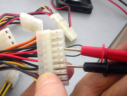
Of course, (in the case of measurements with a multimeter) you can not disconnect the PSU from (thus saving the workload for it), but then I just won’t be able to take a normal picture of the measurement process for you :)
So, I propose to load our PSU with a conventional 8-cm external fan for 12V (you can use two), which we will connect to the “Molex” connector of the subject during the test of the power supply. Like this:
And this is how our Chinese tester (a thing in itself) looks like for checking the PSU, which I spoke about earlier:

As you can see, the device is unnamed. The inscription "Power Supply Tester" (power tester) and that's it. But we do not need a name, we need it to measure adequately.
I signed the main connectors from which this device can take readings, so everything is simple here. The only thing before you start checking the computer's power supply, make sure that you have correctly connected the additional 4-pin 12V plug. It is used when connected to the corresponding socket near the CPU.
Let's take a closer look at this point. Here is a close-up of the part of the device that interests us:

Attention! See the warning label "Use correct connector"? (use the correct connector). If the connection is wrong, we will not be able to check the power supply correctly, we will kill the meter itself! What should you pay attention to here? To the prompts: "8P (pin)", "4P (pin)" and "6P (pin)"? A 4-pin (12-volt) processor power plug is connected to the 4-pin connector, a six-pin additional power connector (for example, a video card) is connected to "6P", to "8P", respectively, an 8-pin . Only this way and nothing else!
Let's see how to check the power supply of this device in "combat" conditions? :) We open it, carefully connect the connectors we need to the tester and look at the screen with the measurement results.

In the photo above, we can see the measurement indicators on the digital display. I propose to sort them all out in order. First of all, you should pay attention to the three green LEDs on the left. They indicate the presence of voltage on the main lines: 12, 3.3 and 5V.
The numerical result of measurements is displayed in the center of the screen. Moreover, both plus values and voltage values with a minus sign are displayed.
Let's take another look at the photo above and from left to right we will go through all the indications of the tester when checking the computer's power supply.
- - 12V (available - 11.7V) - normal
- + 12V2 (12.2V available) - current on a separate 4-pin connector near the processor)
- 5VSB (5.1V) - here V=Volt, SB - "standby" (standby voltage - "standby"), with a nominal value of 5V, which are set at a given level no later than 2 seconds after the unit is connected to the network.
- PG 300ms - "Power Good" signal. Measured in milliseconds (ms). Let's talk about it below :)
- 5V (there is 5.1V) - lines that are used to supply power to hard drives, optical drives, disk drives and other devices.
- + 12V1 (12.2V) - which are fed to the main (20 or 24-pin connector) and disk device connectors.
- + 3.3 V (available - 3.5V) - used to supply power to expansion boards (also present on the SATA connector).
It was we who checked the power supply, which was fully functional (to fill our hand), so to speak :) Now the question is, how to check the power supply of a computer that makes us suspicious? This article began with him, remember? We remove the PSU, "hang" a load (fan) to it and connect it to our tester.
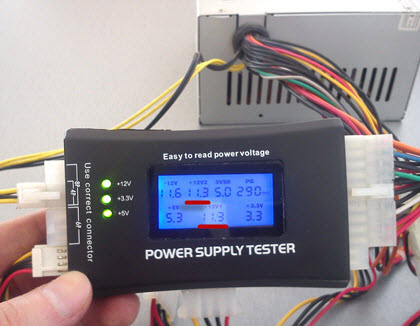
Notice the highlighted areas. We see that the voltage of the computer's power supply along the lines 12V1 and 12V2 is 11.3 V (at a nominal value of 12V).
Is it good or bad? Ask you:) I answer: according to the standard, there are clearly defined boundaries of permissible values that are considered "normal". Everything that does not fit into them - sometimes it also works great, but often it is buggy or does not turn on at all :)
For clarity, here is a table of permissible voltage spread:

The first column shows us all the main lines that are in the BP. Column " Tolerance" this is the maximum allowable deviation from the norm (in percent). According to it, in the field " min" indicates the minimum allowable value for this line. Column " nom" gives the nominal (recommended value, according to the standard). And - " Max" is the maximum allowable.
As you can see (in one of the previous photos), our measurement result for the 12V1 and 12V1 lines is 11.30V and it does not fit into the standard five percent spread (from 11.40 to 12.60V). This malfunction of the power supply, apparently, leads to the fact that in general or it starts from the third time.
So, we found a suspicious malfunction. But how to make an additional check and make sure that the problem is in the low voltage + 12V? With the help of our (most common) multimeter under the brand name " XL830L».
How to check the power supply with a multimeter?
We will start the block as described in, closing two contacts (pins) with a paper clip or a piece of wire of a suitable diameter.

Now - we connect an external fan to the PSU (remember about the "load") and - a 220V cable. If we did everything correctly, then the external fan and the "carlson" on the block itself will begin to rotate. The picture, at this stage, looks like this:

The photo shows the devices with which we will check the power supply. We already considered the work of a tester from China at the beginning of the article, now we will make the same measurements, but with the help of .
Here you need to digress a bit and take a closer look at the computer's power supply connector itself. More precisely, the tensions that are present in it. As we can see (in one of the previous photos), it consists of 20 (or 24-four) wires of different colors.
These colors are used for a reason, but they mean very specific things:
- Black the color is "ground" (COM, it is also a common wire or - mass)
- Yellow color + 12V
- Red: +5V
- Orange color: +3.3V
I propose to check and consider each pin separately:

So - much clearer, isn't it? Do you remember colors? (black, yellow, red and orange). This is the main thing that we need to remember and understand before we check the power supply ourselves. But there are a few more pins that we need to pay attention to.
First of all, these are the wires:
- Green PS-ON - when it is shorted to ground, the power supply starts up. This is shown in the diagram as "PSU On". It is these two contacts that we close with a paper clip. The voltage on it should be 5V.
- Further - gray and the signal "Power Good" or "Power OK" transmitted through it. Also 5V (see note)
- Immediately behind it is purple with the marking 5VSB (5V Standby). This is five volts of standby voltage ( duty room). It is supplied to the computer even when it is turned off (the 220V cable must, of course, be connected). This is necessary, for example, in order to be able to send a command over the network to a remote computer to launch “Wake On Lan”.
- White (minus five volts) - now practically not used. Previously, it served to provide current for expansion cards installed in the ISA slot.
- Blue (minus twelve volts) - at the moment they consume interfaces "RS232" (COM port), "FireWire" and some PCI expansion cards.
Before checking the power supply with a multimeter, let's consider two more of its connectors: an additional 4-pin for the needs of the processor and a "Molex" connector for connecting optical drives.

Here we see the colors already familiar to us (yellow, red and black) and their corresponding values: + 12 and + 5V.
For greater clarity, download all the PSU voltages in a separate archive.
Now let's make sure that the theoretical knowledge we have received is fully confirmed in practice. In what way? I suggest starting with a careful study of the factory "sticker" (sticker) on one of the real ATX standard power supplies.

Pay attention to what is underlined in red. "DC OUTPUT" (Direct Current Output - DC output value).
- +5V=30A (RED) - plus five IN, provides a current strength of 30 Amperes (red wire) We remember from the text above that it is + 5V that comes in red?
- +12V=10A (YELLOW) - plus twelve IN we have a current of ten amperes (her wire is yellow)
- +3.3V=20A (ORANGE) - line three and three tenths IN can withstand a current of twenty amps (orange)
- -5V (WHITE) - minus five IN- similar to the one described above (white)
- -12V (BLUE) - minus twelve IN(blue)
- +5Vsb (PURPLE) - plus five IN on duty (Standby). We have already talked about him above (he is purple).
- PG (GRAY) - Power Good signal (gray).
On a note: if, for example, the standby voltage, according to measurements, is not equal to five volts, but, say, four, then it is very likely that we are dealing with a problematic voltage stabilizer (zener diode), which should be replaced with a similar one.
And the last entry from the list above tells us that the maximum output power of the product in watts is 400W, and only channels in 3 and 5V can provide a total of 195 watts.
Note: « Power good"- "Food meets the norm." Voltage from 3 to 6 Volts (nominal - 5V) is generated after the necessary internal checks through 100 - 500ms(milliseconds, it turns out - from 0.1 to 0.5 seconds) after switching on. After that, the clock generator chip generates the initial setup signal. If it is missing, then another signal occurs on the motherboard - a hardware reset of the CPU, preventing the computer from working with abnormal or unstable power.
If the output voltages do not correspond to the nominal ones (for example, when it decreases in the mains), the Power Good signal disappears and the processor automatically restarts. When all necessary current values are restored "P.G." re-formed and the computer starts working as if it had just been turned on. By quickly turning off the “Power Good” signal, the PC “does not notice” problems in the power system, because it stops work before errors and other problems associated with its instability can appear.
In a properly designed block, the issuance of the “Power Good” command is delayed until power is stabilized on all circuits. In cheap PSUs, this delay is insufficient and the processor starts to work too early, which, in itself, can even lead to distortion of the contents of the CMOS memory.
Now, armed with the necessary theoretical knowledge, we understand how to properly check the power supply of a computer using a multitester. We set the measurement limit on the DC scale to 20 Volts and proceed to check the power supply.

We apply the black "probe" of the tester to the black wire "ground", and we begin to "poke" with red into all the remaining ones :)
Notes e: do not worry, even if you start to "feel" something wrong, you will not burn anything - you will simply get incorrect measurement results.
So, what do we see on the screen of the multimeter in the process of checking the power supply?

On the + 12V line, the voltage is 11.37V. Remember, the Chinese tester showed us 11.3 (in principle, a similar value). But it still does not reach the minimum allowable of 11.40V.
Also pay attention to two useful buttons on the tester: "Hold" - holding the measurement readings on the display and "Back Light" - backlighting the screen (when working in poorly lit rooms).

We see - the same (not inspiring confidence) 11.37V.
Now (for the sake of completeness) we need to check the power supply for compliance with the rating of other values. Let's test, for example, five Volts on the same Molex.
Black "probe" to "ground", and red - to the red five-volt pin. Here is the result on the multimeter:

As you can see - the indicators are normal. Similarly, we measure all other wires and compare each result with the nominal value of.
Thus, checking the power supply showed that the device has a very low (relative to the nominal) voltage of + 12V. Let's, for clarity, once again measure the same line (yellow color on an additional 4-pin connector) for a fully functional device.

We see - 11.92V (remember that the minimum allowable value here is 11.40V). So we are well within the tolerance.
But checking the computer's power supply is still half the battle. It is necessary to repair it after that, and we analyzed this moment in one of the previous articles, which was called.
I hope that now you yourself, if necessary, will be able to check the power supply of the computer, you will know exactly what voltages should be present at its terminals and act in accordance with this.