A.Urmilovg.Novgorod-Volynsky, Zhytomyr region. Relay K1 (RES6 passport RFO.452.103) is connected to the anode circuit of the thyratron, the group of normally open contacts of which is connected in parallel with the self-locking contacts of the musical bell relay (or through these contacts they feed an ordinary apartment bell). To exclude false alarms of the sensor device and spontaneous ignition of the thyratron, a parametric voltage stabilizer was introduced, made on the VD1 zener diode and a short-circuit ballast resistor. A constant supply voltage of 170 V remains unchanged when the mains voltage fluctuates from 180 to 250 V. = DOOR SENSOR Sensor E1 in the form of an aluminum rivet, resistor R1 (it can be from 1 to 10 MΩ) and a thyratron are placed in a small case mounted on the input doors outside. VHF circuit To control the operation of the sensor opposite the thyratron, a hole was drilled in the case. At the moment the rivet button is touched, the thyratron dazzlingly flashes. Setting up the sensor device is reduced to setting the variable resistor R5 to a voltage of 170 V across the oxide capacitor at a minimum mains voltage (180 V) - this voltage can be applied, for example, from an autotransformer. in strict accordance with the diagram after determining the neutral and phase wires. Literature1. "Door sensory bell". - Radio No. 1-82, p. 54. RADIO No. 6-90, p. 77 ....
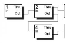
For the circuit "Doorbell time limiter"
Doorbells, as you know, turn on the button at the door. They work as long as the button is pressed. If the button is accidentally short-circuited, which happens when it is made of low-quality plastic, or it is specially closed, for example, with a match, it will work continuously. not designed for this mode of operation. At best, it will burn, and at worst, a fire is possible. But even when the caller keeps the button pressed for a long time, the prolonged ringing gets on the nerves, so it is desirable to limit the ringing time to 5-7 seconds. The scheme described below (see figure) allows you to do this. ...
For the scheme "Power supply of an imported radiotelephone"
Resistor R1 attenuates the current pulses through the rectifier bridge at the moment of switching on, restrains the current through the primary winding T1 when the mains voltage is too high, and burns out in cases of very high mains voltage or an interturn short circuit in the transformer. Zener diode VD2 determines the value of the output voltage (if necessary, select a copy of the zener diode with the load turned off). The HL1 incandescent lamp serves to limit the power released on the VT1 transistor in nominal mode and limit the short-circuit current. If under load the voltage decreases by more than 1 V, a more powerful lamp should be used (one or two lamps from a 13.5 V garland can be soldered in parallel to HL1). ...
For the "VER 2.0 radiotelephone handset in a housing ... from mk"
When setting up the radiotelephone described in , there were problems finding an inexpensive handset body. Accidentally came across a faulty calculator, which was not subject to repair due to the peculiarities of the electrical circuit - the so-called "empty case" and LSI in the form of one flat drop on the circuit board. By itself, the elegant case of the HL-812E calculator measuring 125x70x18 mm was pitifully thrown away, and after some thought, it was decided to try to assemble a radiotelephone handset circuit. A fairly deep niche measuring 54x78x8 mm, in principle, made it possible to place all the details with a slight refinement of the bottom cover (I had to drill and cut two holes in it: for the microphone capsule - in the lower right corner, and the phone - in the upper right corner). To install a telescopic antenna, a hole was drilled in the left side of the upper end of the calculator case. The lower end of the antenna is fixed with a small bracket to the board of the former calculator. Tracks going to the BIS from the buttons 0; 1; 2; 3; ...9; "OFF"; "C" and "AC" must be cut and unsoldered to the corresponding points of the tube circuit (Fig. 1 c). Scheme of underheating of the soldering iron When assembling, small-sized resistors ULM-0.12, capacitors KD, KM-6, K10-17 and K50-40, electrolytic capacitors of the K53-30 series were used. Instead of ULM-0.12, resistors of the MLT-0.125 W type can be used. The battery compartment at the top of the calculator (under the LCD indicator) is used for its intended purpose - to accommodate the handset's battery. The entire assembled circuit is closed with a self-made protective cover measuring 105x55 mm, fixed with self-tapping screws through the regular holes of the case. Unused keyboard buttons, such as "V ";"%"; "MR"; "M-"; "M+"; V; "x";"-";"+"; "=";".", can be covered with home-made, made of plastic of the same color as the body, with plugs, gluing them to the calculator board. In the "+" button, several holes should be drilled with a diameter of 1.5 ... 2.0 mm. This button is not glued to the board, as it closes the microphone and is glued to the top cover. Also, in the top cover, you need to drill several holes (or one with a diameter of 4 mm) above the telephone primer. As a result...
For the scheme "MELODIC RING FROM... WRISTWATCH"
Consumer ElectronicsMELODY FROM... WRIST WATCHES. KULIKOV, 443072, Samara-72, 18 km of Moscow Highway, 13-61l I had an imported electronic wristwatch in a metal case with a faulty indicator. There are many names for watches of this type (for example, "Montana"), but they are all the same. With the current time on the indicator, the melody is turned on by constantly pressing the "AL.TM" button and briefly pressing the "DATE" button. This principle is implemented in the call. The watch battery is replaced with ingredient A343, which lasts for several years. The element is best soldered, because. salt often appears on the "-" and it oxidizes. Instead of a piezo emitter, a load is necessarily turned on - a capacitor C1 of the KM type (between the clock case and the "spring"). An amplifier is added on a transistor of the KT829 (KT827) type with a large Vst, the load of which is a speaker of 0.5 W, 4 ohms. Moreover, for some hours the volume turned out to be insufficient, I had to add an additional amplifier to the KT3102D. The power supply is the simplest 15 V rectifier with a permanent connection of the primary winding to the network. Because some melodies have a long sound time, which is undesirable for a call; it is supplemented with a timer that limits the sound time to a few seconds. Schematic borrowed from . Setting up a time relay - ibid. Literature 1. Radio.-1990.-N 2. c.32.Radio amateur 7/96...
For the scheme "Doorbell from an old phone"
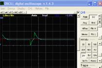
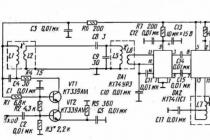
Electronic telephones fail for various reasons. And there is either no time to fix the phone, or it is already impractical, or maybe just a different, more perfect fellow has been working in its place for a long time. But if the old device has not yet been thrown away, then its filling can be used. As a rule, an electronic telephone set consists of a dialer and key circuit, as well as a conversational circuit. When a signal is received from the telephone exchange, a ringing device is activated, in other words, an electronic bell. This is the part of the device that we need. The telephone ringer is often built on a specialized integrated circuit (IC) of the KR1436AP1 type. The microcircuit is powered by a special power supply unit with hysteresis. It provides power to the remaining components: LF generator, HF generator and output amplifier. The occurrence of sound vibrations is provided by two RC circuits. The TC112 triac and the circuits on it are a low-frequency generator with its RC circuit, which is connected to pins 3 and 4, and generates pulses with a frequency of approximately 10 Hz. They control the operation of the RF generator with the fundamental frequency (f1) set by the RC circuit connected to pins 6 and 7. Thus, at the output of the second generator, pulses with alternating frequencies f1 and f2 are generated. Frequency ratio f2/f1 = 1.25. As a result, a characteristic trill sound is obtained at the output of the microcircuit. The KR1436AP1 microcircuit is made in a miniature DIP-8 package. The main electrical parameters are given in the table 1. Let's take a quick look at the processes in the bell circuit shown in Fig. 2. AC mains voltage 220 V, 50 Hz is supplied through a bell button and a quenching circuit of two capacitors C1 and C2 and resistors R1 and R2. Next, the AC voltage is rectified by a bridge rectifier ...
For the "Simple electric musical bell" scheme
For scheme "Caller for hubs"
Telephone hubs, as well as old industrial telephone hubs such as KD-6 and KS-6, do not have a loud call, and therefore, when used in rooms with a high noise level, the call may not be heard. I supplemented my concentrator, as well as many KD-6s, with a public address device with a regular telephone call, which is included instead of an acoustic signal capsule. The principle of operation of the device, the diagram of which is shown in the figure, is as follows. When a call arrives at its input, the transistor opens. A positive pulse of the collector circuit of the transistor opens the KU201K thyristor and starts working. The remaining parts form the simplest parametric stabilizer. Alternating current from a separate step-down transformer is used to power the bell and transistor. Since a non-sinusoidal voltage is supplied through the thyristor, call should be installed in a vertical position. The polarity of its inclusion is determined empirically. The MP16B transistor can be replaced by MP26B. The thyristor can be replaced by KU202N. Resistor R2 - wire.A. WHITE, Donetsk region, Artemovsk...
For the scheme "MINIATURE RADIO TELEPHONE"
Sometimes it happens that a home radiotelephone becomes morally obsolete and ceases to please: new models appear with which you want to “change” for the joy of yourself and your loved ones.
It also happens that it suffers from a local malfunction: for example, my Texet TX-D5300 phone, after falling to the floor, stopped displaying some characters on the display, and reading information turned into flour for me. Parsing the device and improving the contacts of the display with the printed circuit board did nothing gave.
Then we are coming to you!
Do not part with your loved ones or new life for old things
Unfortunately, there are hundreds and thousands of such and similar cases. A small (up to 1000 rubles) cost of such devices suggests that the owner will replace such a phone without regret, since the profitability of the repair will outweigh the cost of the product itself.
Nevertheless, such "lame ducks" - radiotelephones with minor breakdowns, are quite suitable for breathing new life into them with the hands of a radio amateur. For example, it is not difficult to make a remote signaling device for opening the front door from a "toy".
You can go even further and teach the "lame duck" to notify with sound about any other change in the controlled space within the apartment or office. The main thing is that the transmitting and receiving paths are working, and the “tube search” function works. Next, I will tell you how to make a useful household item out of such a half-serviceable wireless kit.
The result of the alteration: I was looking for a tube - I found an open door

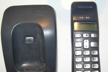
On fig. 1 shows the appearance of the wireless kitTexetTX-D5300: base and one handset.
To finalize the standard kit (base + handset), you will need to take a few simple steps. Here they are:
- disassemble the base of the radiotelephone (remove the case to access the printed circuit board);
- connect a two-wire cable with a maximum length of not more than 1.5 m in parallel with the contacts of the “search tube” button (to avoid false positives from AC voltage pickups from mains wires);
- connect the other end of the loop to a limit switch (for closing) or a reed switch for opening (with a normally closed group of contacts) installed on the front door box (see details below);
- install (fix) the base of the radiotelephone here, not far from the "remote switch";
- using a standard adapter, connect the base to a voltage of 220 V;
- connect the remote handset to another (additional) network adapter with an output voltage of 3-5 V, so as not to depend on the discharge of batteries or accumulators in the handset;
- install the handset with the adapter in the right place, for example, not far from the desktop.
Let's take a closer look at these steps.

On fig. 2 shows a view of the base with the housing cover removed.
In the center of the printed circuit board (Fig. 2) there is a button with closing contacts; it has 4 outputs, two of which are connected (duplicate each other). With an ohmmeter, we check the connection in the contact group of the button - when we press it, we reveal closing contacts.
In parallel with them, with a soldering iron with a thin tip and a power of up to 25 W (so as not to damage the radio elements on the printed circuit board), we solder a two-wire cable; there is no need to shield it (Fig. 3).

The connection diagram is quite simple, and, in my opinion, does not even need to publish a separate figure. This is a reed switch connected parallel to the button (on the base) "search for the handset".
The base has nothing to do with it: the trill will sound in 3 seconds
When you press the "search handset" button (in the central part of the base) - provided that the base is connected to a 220 V network and charged batteries directly in the handset - the latter emits a short trill lasting 2.5 ... 3 seconds. Moreover, this happens regardless of whether a telephone line is connected to the base, which made it possible to use the old radiotelephone for other purposes.
With a long (or repeatedly repeated with a frequency of more than 1 time in 5 seconds) pressing the "search tube" button, the sound signal will still be only one, lasting several seconds. The same will happen when opening the door on which the "contact breaker" is installed. This is a feature of the industrial development of the Texet TX-D5300 phone.

On fig. 4 shows a reed switch combined with a magnet on the moving part of the door.
When the door is tightly closed (Fig. 4), the magnet acts with its field on the reed switch and the contacts of the latter open. When the door is opened, the reed switch is in normal mode with closed contacts. This state is transmitted to the base and the handset emits a heart-rending beep. As a reed switch, I use KEM-3-1 with three contacts.
To power the handset of a radiotelephone located within 30 meters from the base, I use an adapter for powering a Nokia cell phone with an output constant voltage of 3.7 ... 4.2 V. In this case, any unnecessary charger with an output voltage in the specified range will do.

Rice. 5. Radio tube and new power adapter
Technical characteristics of the base unit TX-D5300 from Texet
- DECT GAP standard (possibility to register additional handsets from other manufacturers);
- menu in Russian;
- phone book for 50 names and numbers (repeat the last 10 dialed numbers);
- identification of the caller's number (AON / Caller ID) with a memory of 40 numbers
- the ability to connect up to 5 handsets (wireless mini-PBX): internal connection between handsets;
- operating frequency: 1880-1900 MHz;
- range of the Texet TX-D5300 wireless kit indoors / outdoors up to: 50 m / 300 m;
- caller ID only in Texet TX-D5300 Black;
- interfaces: Texet TX-D5300 Black RJ-11 input.
Security and service functions in the Texet TX-D5300 Black model:
- mute the microphone;
- keyboard lock;
- time indication;
- battery discharge indication;
- indication of going out of the communication zone of the base unit;
- tube search.
The base is powered by a 6.5 V DC power adapter (current consumption 150 mA).
The phone is powered by two AA batteries, 1.2 V and 550 mAh each.
Breaking news: the toilet is already free...
As I have already noted, there can be many options for using the modified device: there would be something to signal.
For example, in addition to the proposed alarm about opening the front door, if placed differently, the sensor can happily report whether the toilet or bathroom is occupied, whether a leak has visited us somewhere, whether the fan or air conditioner is turned on in another room. And there are also loggias, which sometimes also open - but you never know what latest news we would like to receive?
To implement any of these ideas, you just need to take care of placing the contact sensor directly in the zone of its operation and place the base of the radiotelephone nearby.
Instead of contacts of a reed switch (button or switch to close), you can even use an electronic circuit with control based on electronic keys (microcircuits K190KT1 - K190KT2, multiplexers or relays). But this is a completely different story, more complicated.
An interesting idea: our development can be used for real estate protection. This will require one tube and one neighbor. If you install the phone with a neighbor in the stairwell (with the condition of prior consensus with her), then during your long absence, this same neighbor, who is not indifferent to other people's secrets, will always know that “someone has opened the door” for you, and will be able to I hope to call "the right place" in time.
So enjoy and prosper!
How to make a Skype Telegram wireless telephone extension cord with your own hands. Everyone who is connected with computers knows Skype very well. Working on Skype allows you to negotiate almost free of charge and see the interlocutor who is on the other side of the world. Skype is also very convenient for local calls, when you need to hold lengthy discussions or consultations. In ordinary life, additional communication equipment other than a microphone, speakers or headset is not required. It is convenient to work with such a communication set when negotiations are not long or you constantly need to access a computer. And when conducting lengthy negotiations on abstract topics, constant connection to a computer can tire and hamper freedom. To eliminate this inconvenience, to plug radiotelephone to a computer. A study of the documentation for various types of radiotelephones showed that there should not be any difficulties in connecting to a computer. From telephone trash, I managed to pick up a Panasonic KX-TCD700 entry-level DECT phone, the phones are reliable and can still be found in offices. This is a 900 MHz radiotelephone with a communication range of up to 70 meters and, most importantly, requires “AA” batteries for its power, and not special batteries. With the choice of a donor radiotelephone, the question of how to make a radio extender for Skype with your own hands began to be resolved.
How to make skypophone with your own hands
1. We insert the batteries into the handset, connect the 220v adapter to the base and check the operation of the radiotelephone when connected to a conventional telephone network. The device must be working. The subtleties of setting the base tube are given in the instruction manual.
Phone is a donor
2. We open the base. At first it was uncomfortable at the sight of a dense installation. But the study of the circuit and the abundant marking of the elements on the board made it possible to calculate and find the connection points to the conversational node of the board. The connection points can be chosen as guidelines when adapting to a computer and other phone models, in my opinion, any radiotelephone will be able to connect. It was necessary to find the transmit and receive signals - going to the conversational node of the telephone line and take them to connect to the microphone input and line output of the computer. According to the scheme, these are the signals RX-AF and TX-AF, respectively. To connect to a computer, a test point TP82 and a capacitor C62 are selected (test point TP96 is not marked on the board).
Base internals
Scheme fragment
Fragment of the wiring diagram
3. The connection cable is taken from the cheapest computer headset, it has pleasantly accelerated the work. The ends of the cable conductors are cleaned and covered with solder.
4. To decouple galvanic connections along the signal circuits and limit the signal strength, the connection to the control points was made through two RC circuits. An RC circuit is a series connection of a 0.1uF capacitor and a 5.1kΩ resistor. Soldering points are shown in the wiring diagram and photograph. Extension wires are soldered to the test points. The capacitors are glued with hot glue, and the resistors are fixed in a volumetric way.
computer headset
Connecting to the board
Parts filled with hot glue
5. The headset cable is passed through the hole in the RG-45 connector and soldered with the corresponding ends to the capacitors. the cable is fixed in the connector with hot glue. The RX signal goes to the microphone input, the TX signal goes to the line output. Passing the cable through the connector performed at the same time foolproofing. I admit that when the phone is connected to the telephone network at the same time, some troubles may occur, for example, with a microphone input.
6. We assemble the base and connect the radiotelephone. The self-made radio extender based on the Panasonic KX-TCD700 phone started working right away, it was only necessary to correctly adjust the signal strength using computer settings. Tests have shown the performance of the device at a distance of 30 meters from the base (there was a comfortable sofa 😉). Since it is not possible to establish a connection in the program from a phone connected to the computer, the connection is established in the usual way, and then you can pick up the handset by pressing the key and start a conversation.
It follows from the features of the connection that the speech signal became more compressed (features of the radiotelephone), but at the other end, the interlocutors usually did not notice anything unusual, except for an incomprehensible empty space in front of the computer when the video link was on. At the end of the conversation, it's a good idea to return to the computer and check the connection is broken.
From a further improvement of a home-made device, you can consider the option of end-to-end control of speakers or a computer headset, which will turn off when removing the handset from the base or turning it on, but this will certainly complicate the design.
At the request of readers, connection points for Panasonic phones KX-tcd410rum (rus) / KX-tcd412rum (rus) / kx-a141rum (rus) / kx-a142rum (rus) and , KX-TC1245RUB ( , ) were drawn. Friends, do not forget to report the results of the alteration, the site is working for thanks.
Often, fishing, in the forest, and in many other situations, there is a need for communication. In recent years, many cheap models of radio stations have been released on the market to work in the decimeter band 446 MHz recently allocated for “civilian” communications. But they (in my opinion) have some drawbacks: only eight operating frequencies; the standard antenna is fixed, as they say, “tightly”, and this does not make it possible to use antennas of other types; When changing the power supply, all settings must be re-entered. In general, of course, the walkie-talkies are not bad. And the price of professional "bites". Nevertheless, for these purposes, radio amateurs construct various types of low-power stations themselves, but the goal does not always justify the investment: the time spent on design, search for components, manufacturing is too high. Meanwhile, many somewhere "in the attics" have already served their age, but quite suitable radiotelephones for radio frequencies of 46 ... 49 MHz or others are lying around.
In practice, by means of rather minor alterations, quite good radio stations can be made from such old radiotelephones, providing quite reliable communication at a distance of 300 ... 500 meters. Both handsets and base units can be used. But, of course, tubes are preferred.
For rework, it is better to use phone models in which the receiving path is built according to a double frequency conversion scheme, as it has greater sensitivity. First of all, it is necessary to electrically completely separate the receiving and transmitting paths, dismantle the pilot signal conditioners and decoders from the printed circuit boards, and everything else that is not needed in the circuits of radio stations. At the discretion of the radio amateur, certain switches of the “reception-transmission” mode are mounted. You can enter a volume control, install a suitable dynamic head (if the ULF has sufficient output power). If only one pair of radio stations is manufactured, then it is quite possible to get by with those quartz resonators that are in one set of radiotelephone, communication will be carried out at two different frequencies. If it is necessary to manufacture more than two radio stations, then you will have to look for identical sets of radio telephones, which, of course, is clear to everyone who will be engaged in alteration: I just want to say here that the contours of telephones are rebuilt over a wide range, and rewinding of the contour coils is not necessary, it is enough just to rebuild and adjust them according to existing methods. If it is known in advance that the radio stations will be operated in areas remote from populated areas, you can slightly increase the output power of the transmitters.
Since cordless handsets do not have a noise reduction system, you must enter it yourself. MC3361 and similar microcircuits have the necessary resources for this. In the places vacated after the removal of unnecessary elements, a noise reduction circuit is mounted according to the above scheme (the circuit of the KENWOOD TH-22 radio station was used). Transistor VT1 - any silicon, diodes VD1; VD2 - the same, any of those that were on the board. The transistor key can be included both in the ULF power circuit and block its input.
Thus, the radio stations are ready. The time of alteration of two radio stations does not exceed 8...10 hours. The number of track cuts and jumpers on the board is minimal, almost all newly installed elements are mounted in place of the removed ones, and radiotelephones get a second life. At least in children's hands!
In the same way, I converted the radiotelephone handsets to work in the meter range, replacing the RF transistors with others with a higher cutoff frequency, and reducing the number of turns of the inductors (it is better to rewind with a larger diameter wire!) On the existing frames with the same cores. The number of turns decreases as many times as the frequency increases. But at the same time, not every design will enable stable operation of the station, since the printed circuit board is on a one-sided getinax, and therefore it is necessary to use shielding of individual stages and the receiver and transmitter: there is a tendency to self-excitation. You can somewhat reduce the latter if you reduce the number of turns of the loop coils slightly, and at the same time reduce the capacitance of the capacitors. Quartz resonators were used the same as those used in the tube, their ninth harmonic was used (on quartz, as a rule, the third harmonic is indicated). The reception and transmission frequencies were different. The station was paired with the already named TH-22E. The results were weak, but on the basis of the elements themselves in radiotelephones, such stations can be built, you just need to make a new board that meets the requirements for the VHF band.
Harald Akermanis, Ogre, Latvia
Sometimes it happens that a home radiotelephone becomes morally obsolete, ceases to please as before, because modern models appear that you want to “insert” into your interior to the delight of yourself and your loved ones. It also happens that it is overtaken (overtaken) by a local malfunction; for example, my phone Texet TX-D5300 after falling to the floor stopped displaying some characters on the display, and reading the information turned into flour for me. Parsing the device and improving the contacts of the display with the printed circuit board did not give anything. Unfortunately, there are hundreds and thousands of such and similar cases. A small (up to 1000 rubles) cost of such “toys” suggests that the owner will replace such a phone without regret, since the cost of repairs will outweigh the cost of the product itself.
Nevertheless, household radiotelephones with minor and local malfunctions are quite suitable for breathing "new life" into them with the hands of a radio amateur.
For example, it is not difficult to make a remote signaling device for opening the front door out of a “toy”; and this task skillfully embodied in reality will allow you to go even further and notify with sound about any other (with the appropriate connection) change in the controlled parameter within the same apartment (office). The main thing is that the transmitting and receiving paths are in good order and the “tube search” function works. Next, I will tell you how to make a useful household item out of such a half-serviceable wireless kit.
On fig. 3.29 shows the appearance of the Texet TX-D5300 wireless kit, which consists of a base and one handset.
To finalize the basic (regular) kit (base + handset), you will need to take a few simple steps. Here they are:
Disassemble the base of the radiotelephone (remove the case to access the printed circuit board);
Connect a two-wire loop with a maximum length of not more than 1.5 m in parallel with the contacts of the “search tube” button (to avoid false alarms from AC voltage pickups from mains wires);
Connect the other end of the loop to a limit switch (for closing) or a reed switch for opening (with a normally closed group of contacts) installed on the front door box (see details below);
Install (fix) the base of the radiotelephone here, not far from the "remote switch";
Using a standard adapter, connect the base to a voltage of 220 V;
Connect the remote handset to another (additional) network adapter with an output voltage of 3-5 V, so as not to depend on the discharge of batteries or accumulators in the handset;
Install the handset with the adapter in the right place, for example, not far from the desktop.
Let's take a closer look at these steps.
On fig. 3.30 shows a view of the base with the housing cover removed.
In the center of the printed circuit board (as seen in Fig. 3.30) there is a microbutton with closing contacts; it has 4 outputs, two of which are connected (duplicate each other). With an ohmmeter, we check the connection in the contact group of the button - when we press it, we reveal closing contacts. In parallel with them, with a soldering iron with a thin tip and a power of up to 25 W (so as not to damage the radio elements on the printed circuit board), we solder a two-wire cable; there is no need to shield it (see Figure 3.31).
The connection diagram is quite simple, and, in my opinion, does not even need to publish a separate figure. This is a reed switch connected parallel to the button (on the base) "search for the handset".
More recently, LEDs were considered a novelty, and at present they are already massively used for additional lighting and room decor. LED strip is widely used to create exclusive lighting solutions by designers ...
In accordance with state regulations, at enterprises with dangerous working conditions, lighting equipment of an increased explosion protection class must be used without fail.
The popularity of LED products in our country and around the world is explained very simply. LED fixtures are the most economical lighting option. Having paid once, you forget about replacing the source for a very long time ...