Long gone are the days when the radio scanner was the lot of the elite, now even schoolchildren can play it!
Many probably remember the 90s or 2000s, when serious devices like AOR or ICOM cost about a thousand dollars and most of us could only dream of buying such a radio scanner. But time does not stand still, and now, thanks to the DVB-T SDR USB TV tuner on the RTL2832U + R820T chip (RTL2832U + R820T2) and special software, you can make a broadband SDR radio receiver from it for just $10.
What is a radio scanner? A radio scanner is a special broadband receiver with which you can listen to service radios and radio stations, that is, you can receive frequencies: traffic police, police, air, railway, emergency situations, maritime, radio amateurs, private security companies, taxis, etc.
Now, to listen to the above services, it is enough to have a personal computer with Windows OS
Description of work
DVB-T TV USB tuner has the ability to work in SDR mode. All that needs to be done is to replace the specialized software instead of the original driver. Such a tuner is capable of providing radio reception to all radio stations operating in the frequency range from 24 MHz to 2.2 GHz, including SI-BI radio stations, amateur radio bands 10 m, 2 m and 70 cm, air band, LPD walkie-talkies, taxi drivers, GSM spectra and others with AM, FM, WFM, NFM, CW, SSB modulations. To operate such a radio, you do not need a separate sound card, just insert it into the USB connector of a computer or tablet, install drivers, launch the receiving program and enjoy the reception. Span - 3.2 MHz, i.e. you see all the stations in that range at the same time. Frequency tuning - with the mouse wheel. Comes with a 70 cm antenna.
Specifications:
Frequency range: 24 - 1750MHz
Modulation: AM, FM, NFM, LSB, USB, CW (ADS-B, D-STAR, AIS and more...)
Span: variable from 250kHz to 3MHz
Sensitivity: 0.22mKv (at 438MHz in NFM mode)
Receiver input impedance: 50 ohm
Band Filters: External only
ADC bit depth: 8bit
Dynamic Range: 50dB (in CW mode)
Received signal delay: 340ms
Interface: USB 2.0
PC requirements: any modern
Operating system: Windows, Linux, Android
Wideband FM radio
The receiver of the frequency modulated signal for the range of 36 MHz - 920 MHz.
The receiver was built to monitor the work of Volgograd radio amateurs - ultrashortwaves (144-146 MHz), and since only a Chinese AVOmeter (and a Soviet TV - see below) was used for tuning, I had to use a purchased RF unit - a channel selector, to convert sound according to the first IF; the only home-made unit is assembled - a sound UFC with a PLL from the RADIO magazine 11/89 p. 48, the authors V. Bogdanov, V. Pavlov (how to simplify and the printed circuit board, see below), ULF any (ready-made ULF TV board was used on K174UN7).
A phase-locked loop amplifier is needed because the selector selects a very wide signal band - 7 MHz, but it is necessary to detect 15 kHz, of the tested designs, it is the indicated PLL-amplifier that effectively holds the signal.
Sensitivity and selectivity are determined by the channel selector you can get your hands on.
According to subjective data, they are taken on a piece of wire 1m stretched from the window, in a high-rise microdistrict, almost the city center:
home radio extenders of the range 36-49MHz within a radius of 150m;
Volgogradvodokanal, Ambulance - in the area,
Volgograd-Volzhsky taxi on call 36-42MHz (rst "Len") = this is on the first (I-II according to the directory) range of the selector to the first TV channel.
Up to the fifth TV channel: Repeaters 144.5 and 145.675 MHz of ultrashortwaves and radio amateurs 144-146 MHz from adjacent areas,
Volgograd police and traffic police at 148 MHz,
military and FAPSI channels up to 160 MHz sold to oil companies for telephones and used by semi-illegal trunk radio (stations) telephones,
paging transmissions - try to decrypt, for example, with the POCSAG program from the Internet,
behind TV channels - 300-400 MHz (SKM-24 does not catch) trunk rst and long-range radiotelephones, all from adjacent areas, some beyond 30 km = this is on the second (III) range of the selector.
Up to 21 UHF TV channels - federal cellular network "Sotel" 450-470 MHz (Cellular, NMT = 450 standard) (whole city),
for UHF TV channels home radio extenders ~ 650 MHz radius 350 m,
at the end of 825-870 MHz - the Unicel (Indigo) cellular network (cellular, AMPS standard) is caught only when the selector is set to 33-35V instead of 28V and, according to experience, on 4 selectors out of 5 = this is the third (IV- V) range (or SKD-24);
of course, all VHF, FM radio stations and TV sound are received.
Note that the beginning of the range (I-II= 36MHz, III= 120MHz, IV-V= 430MHz) corresponds to 0V on the varicap control, the end of the range (I-II= 110MHz, III= 230.400MHz, IV-V= 900MHz) +33 .35V.
For 2002, the cost of components purchased at the Volgograd radio market was:
Channel selector (SK-V-41 new) for 100 rubles (SKM-24 + SKD-24 for 80 rubles;
rootless Asian selector with a torn antenna socket for 10 rubles);
2 blocks of settings resistors with blocks of push-button switches from the VM-12 Vidic for 40 rubles;
Microcircuits, transistors, Krenki about 50 rubles;
the rest is amateur radio rubbish - borrow from friends or prepare another 50-100 rubles for the market;
total 280 rubles for a receiver offered by Moscow firms selling special equipment for 450 USD. minimum (if there is no police nearby).
For radio amateurs With extensive experience, the list of purchased parts is enough for manufacturing, so they may not read further, I will tell the rest of the path traveled during manufacture.
How to make a receiver
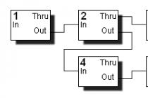
Receiver Block Diagram
Fig.1. Receiver Block Diagram (Click for large image)
To begin with, we make a sound amplifier with a PLL - see RADIO magazine 11/89 p.48.
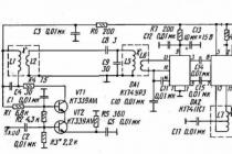
Schematic diagram of the amplifier:

We simplify the existing scheme as follows:
We leave only two circuits of the FSS filter, crossing out parts C6, C7, L3, L4 on the diagram. Now the left terminal of C8 comes from the upper terminal of L2 (the bottom of L2 remains grounded).
Transistors VT1, VT2 KT339A (in metal) are difficult to get, besides, for some reason, the IF is self-excited with them. Let's apply KT339AM (in plastic).
Instead of the varicap assembly VD1 KVS120A1 (not available and there is no reference book with a pinout), we use KVS111A or B with the simultaneous replacement of C19 with 31Pf +/-5% (it was 19Pf).
We change VT3 KT3102A to any KT315 (soldered from the old board).
KP307 with any letter (other field-effect transistors will not work)
We wind all coils on frames from circuits from the IF board of a color lamp TV - vertical, 7.5 mm in diameter with carbonyl iron trimmers (L7, L8 also, a brass core is not needed). We cut the coils to 15-20 mm, melt the legs into the right places of the base, cut the screens as well - leave the lower part. Inside the screen will fit part of the details of the contours (wrapped together with paper, for insulation). The number of turns changes accordingly: L1 and L5 are 8 turns each (instead of 11), L2 and L6 are also 2 turns each, L7 - 2 turns in 2 wires, L8 - 20 turns (instead of 25). Everything can be wound with a wire of 0.2 ... 0.3 mm. It is recommended to connect the upper terminal of the loop coils and communication coils with a common wire (in the diagram, on the contrary, the lower terminals are grounded), and wind the coils in one direction. We wind the communication coil onto the contour coil in its upper part.
Resistors MLT-0.125 with deviations of +/-10% (instead of 2.2K - 2K or 2K4), capacitors C4, C8, C9, C18, C19 \u003d 31Pf, C20, C21 used tubular KT-1 deviations of +/-10%, the remaining capacitors +100% / -50% disk KD or flat square K10-7V. Do not be too lazy to ring the resistors with an AVOmeter for an approximate correspondence to the rating and capacitors for a short circuit (one K10-7V shorted the power supply).
C16 and the Uapch output are not needed, because there is a PLL and there will be manual tuning.
It is with these details that the printed circuit board is made. On a double-sided foil-coated fiberglass 120x65mm - see fig.


Fig.2. Printed circuit board.
The conductors are cut from the bottom, along the contour, with a wood carving cutter - a small V or U shaped cutter, the cut width is 1 ... 2 mm, the rest of the area is left for a common wire. If you want, etch the board in the traditional way in ferric chloride, but leave a maximum of the common wire (respectively, draw the contours of the common wire yourself).
holes can be drilled with a broken needle and a sharpened spatula. On the part of the details, holes for leads not connected to a common wire are countersunk to a diameter of 2 ... 4 mm with a 6 ... 12 mm drill.
Please note: the connection point L1, C4, R4 and the connection point C8, C9, L5 must be isolated from the board - they are connected only at the base of the coil; Also, legs 2,4,6,8,10,11 DA1 isolate from the board (it is better to cut it off). We clean the board from the side of the parts with sandpaper, cover it with a solution of rosin in alcohol (done in 10 minutes), service it with solder. From the side of the parts, it is better to clean only the places around the terminals connected to the common wire. First, we solder R, C, L and screens and control the absence of short circuits, form the R and C leads so that the part rises 1 ... 3 mm above the board, solder the leads with a common wire on both sides of the board. The applied microcircuits and transistors can be soldered several times, but still try not to overheat their conclusions for more than 3 seconds - solder in a checkerboard pattern, if you get a bad solder, wait 10s. Do not use sockets for microcircuits - they cost like the microcircuit itself, and the reliability of the connection is low. We install the VT4 field-effect transistor last, before installing push the candy foil between its terminals (and do not forget to pull it out after soldering). Carefully and stupidly for 30 ... 60 minutes, check the installation for compliance with the details and the absence of short circuits. Input and output - shielded wires, preferably coaxial. 2 power wires, and it is better to turn on the diode D226 or KD105 in the positive one so as not to burn when applying reverse voltage.
Setting up the UPC:
We do not send a signal to the input. We connect the output to any ULF: the input of the tape recorder for recording, the ULF of the stereo complex, Lin IN or Mic IN of the sound card and turn on this ULF. We connect a 9 ... 12V power supply, if the noise from the ULF output has grown, the board somehow works, if not, look for YOUR mistake.
For orientation, I quote the voltages on transistors and microcircuits at a supply voltage of + 10V. VT1: K + 8.5V, B + 3.9V, E + 3.3V. VT2: K + 3.3V, B + 1.1V, E + 0.5V. VT3: K + 10V, B + 3.9V, E + 3.5V. VT4 AND +4V, C +7V, Shutter 0V. DA1: 3.5 +2V, 9 +6.5V, 12,13,14 +2V. DA2: 2 +3V, 3 +3.9V, 5 +10V, 7.8 +2.8V, 10.12 +1V, 11.13 +1.3V. If they differ by more than 2 times, look for a short on the board or change the faulty part.
We solder a plug to the input wire - for example, an antenna, or simply make loops on the signal and common wires.
We open the Soviet TV, in which there is an SKM-24 block and connect to the always free socket with the inscription "pf output", if without a plug, then we use a clothespin to attach the common wire. The rest of the connections are the same. Unscrew the cores from the coils L1-L6. We turn on the TV to a confidently received program and rotate the L7, L8 core, preferably with a screwdriver made from an old toothbrush, until the sound of the same TV program appears.
Then, screwing / unscrewing the cores into the coils L1-L6, we achieve the maximum sound volume. With 2 coils, such a setting is obtained, which is why they got rid of the L3L4 coil. Already now, at the beginning of the 2nd band, you can receive 144 MHz radio amateurs and the police, and at the beginning of the UHF band (if there is SKD-24) Sotel cellular.
Now you can place the board in a screen made of tin from cans, soldering around the perimeter and making the top and bottom covers, then adjust again using the same method. But it works fine even without a screen.
Now the general layout. See. fig.1.
The easiest way for the base is to take a sheet of chipboard with a thickness of 10 ... For the front panel, you can find a sheet of plastic or plywood 1.5 ... 3mm, then screw it from the end of the base; on it, mark the places for buttons, speaker, miliammeter (tuning scale), volume resistors, RRU, Manual frequency control. It is better to place the settings resistor block on the side (at least screw it to the base).
The remaining blocks are adjusted during installation.

Fig.3. Settings block diagram
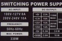
Fig.4. Power Supply Schematic (Click for large image)
Fig.5. Connection diagram of the channel selector SK-V-41 (Click to get a larger image)
Fig.6. Foreign Channel Selector Wiring Diagram (Click to view large image)
The block of touch buttons for selecting programs from the 3rd generation TV is not suitable, because. its triggers do not switch at the desired tuning voltage of 33 ... with dependent inclusion) see Bloc_nastroek.gif. I recommend making a fixed inclusion of ranges, for example, 1-2 buttons are the 1st range, 3-5 - the 2nd, 6-8 - the 3rd. The circuit is simplified, and soldering is not long.
The settings resistor block (8pcs) is also the most stable from VM-12, see Fig. 3. We solder everything except multi-turn resistors and diodes, and the diodes must be turned over because + 35V we supply from the other side. You can use a separate block of 8 resistors from a 3rd generation TV. Very bad large multi-turn resistors from a block of 6 pcs. for example SVP-4-5. We supply the voltage from the output of the resistor block to a conventional variable resistor for operational tuning within 1-10 MHz - this will be our Manual Frequency Adjustment, its value will have to be selected from 10 kOhm for the 825-870 MHz range, up to 50 kOhm for the 144-148 MHz range (do not forget, that radio amateurs or radiotelephones occupy a portion of the range, and multi-turn resistors fail with frequent tuning). Manual frequency tuning - R2, it is selected to obtain the desired operational tuning bandwidth and depends on the selector, for example, for SKM-24 4.7K, SK-V-41 47K. To begin with, connect the button block and the settings block and apply 10V to it, for example, first check the correct connections to the range switching circuit and use an AVOmeter, then the same 10V to the settings circuit, the voltage should change from 0 to 10V.
The power supply will have to be made independently, because. +10…12V and +35V voltages are required, both stabilized see Fig.4. Try to find a transformer that produces an alternating voltage of 9 ... 20V and 30 ... 50V on the secondary windings, if there are inscriptions on the coil, you can recalculate the voltage on the secondary windings, at 220V on the mains. Read, for example, RADIO 4/99 p.38. Sound transformers, TVZ-1-9 (1) or personnel TVK-70 (or 110), require a 33V winding winding: disassemble the transformer and wind a test winding of 10 turns of 0.1 mm wire (for 33V thicker is not needed) in insulation, put back most of the plates and measure the voltage on the new winding, now you can count the number of turns per 1V and wind it up to 33V, and on TVZ you can add another 2 ... 3V to the existing secondary winding (and get 12V out of 9). When assembling, smear the core plates with glue so that it does not buzz. And do not forget - the network winding of low-power transformers is always with a high resistance> 100 Ohm, the number of turns is 1500 ... 2500 (this does not apply to powerful TC-180 (270), you can get the necessary voltages from them, but they are too bulky). It is better to place the transformer in a separate container (for example, from under the Palmira detergent or sour cream) so that it does not heat the rest of the blocks. Rectifiers with stabilizers can be placed in a common unit. If you don’t like Krenki, make ordinary stabilizers on transistors with zener diodes in the base circuit (schemes in almost any RADIO magazine).
I recommend the channel selector SKV-41 or Asian with tuning from a voltage synthesizer (it won’t work from a frequency synthesizer, especially since it is 2 times more expensive) see Fig. 5 and Fig. 6 .. About SK-V-41 read RADIO 3/90 pp. 43-44 (the SK-V-40 is described - 2 entrances, and the SK-V-41 entrance is combined). For wiring and connecting Asian and European selectors, see RADIO 2/98, 3/98, 7/99 and see diagrams of foreign TVs, for example, in the magazine RADIO AMATEUR 12/91, if you take a selector, compare the wiring of the legs from the antenna jack, next to the leg usually 2-3 letters: 1-BU(+12V UHF), 2-BT(0…+33V settings), 3-BH(+12V Range1), 4-AGC(AGC +3…+6V), 5-BL (+12V Range 2), 6-AFC (APCG, can not be used), 7-BM (+12V, constant selector power), 8-missing, 9-IF (IF output to PLL IF). Philips UV936 turned out to be the worst of all - it does not accept the 36-39MHz and 825-870MHz range, working strictly within the TV range. The connection of the SKM-24 and SKD-24 selectors can be seen on the diagrams of Soviet semiconductor TVs, there is also a printed circuit board, the selector control signals are the same (of course, a different wiring), only there is no + 12V DC power supply. The selector SK-V-41 or Asian is installed on a simple scarf from a plate of foil fiberglass (if it is 2-sided, countersink the holes), cutting out patches with a diameter of 3 ... 5 mm with a cutter, around the holes drilled along the selector pins. It is better to solder the selector pins directly, this will not harm the selector, and there is a lot of fuss with the connector. We tie the RC selector with power filters on cut out patches.
The low-frequency signal from the UPF output can be amplified by any ULF (the ULF was used from the control unit BU-3, BU-4, BU-14 TV on K174UN7), even the simplest home-made one on K174UN4, UN7, UN14 is enough, see Fig. 7.

Fig.7. Schematic diagram of the ULF version on K174UN14
Sorry for the missing diagram of the "PLL IF Audio Amplifier" from Radio magazine number 11, 1989 pages 48-49. Unfortunately, the scanner could not be found. If the numbers are for 1989. written off in your district library, you will have to look for a magazine on the radio market, with friends, or in the nearest Radio club, for example, in the Volgograd radio club "Kolos" they do not refuse even a person from the street.
Distribute this text together with the drawings (see above) freely, if possible, please insert a scanned sheet (spread) 48-49 from Radio 11/89. I do not claim absolute authorship, because the very idea (with page indication) was suggested by a friend, a former engineer of the Volgograd special (electronic) enterprise "Aurora".
Disclaimer (excuse)
Read the article of the Criminal Code of the Russian Federation regarding receivers receiving signals not intended for general use, and agree that we need a receiver that accepts all the sound of TV, FM-1 and FM-2 (because we still introduce Manual RF Gain Control - for example, a slotted resistor - and with a RRU voltage of less than 4V, we won’t be able to catch anything except TV and FM, and with Upp = 5 ... 8V we catch local 144MHz radio amateurs, “which makes it possible to interest the younger generation in amateur radio, whose personnel is rapidly aging.”
Article 138. Violation of secrecy of correspondence, telephone conversations, postal, telegraphic or other communications
1. Violation of the secrecy of correspondence, telephone conversations, postal, telegraphic or other messages of citizens -
shall be punishable by a fine in the amount of from fifty to one hundred times the minimum wage, or in the amount of the wage or salary, or any other income of the convicted person for a period of up to one month, or by compulsory works for a term of one hundred and twenty to one hundred and eighty hours, or by corrective labor for a term of up to one year.
2. The same deed committed by a person using his official position or special technical means intended for secretly obtaining information, - up to three months, or by deprivation of the right to hold certain positions or engage in certain activities for a term of two to five years, or by arrest for a term of two to four months.
3. Illegal production, sale or purchase for the purpose of sale of special technical means intended for secretly obtaining information, - or by restriction of liberty for a term of up to three years, or by imprisonment for a term of up to three years with deprivation of the right to hold certain positions or engage in certain activities for a term of up to three years.
Submitted by Miha miha002 (at) vistcom.ru
I am sure that for many of you, as for me quite recently, what is happening on the radio was real magic. We turn on the TV or radio, pick up the cell phone, determine our position on the map using GPS or GLONASS satellites - and all this works automatically. With RTL-SDR, we have an affordable way to look inside all this magic.
As already mentioned, RTL-SDR is a whole family of cheap TV tuners capable of performing the function of an SDR receiver. These toys have different names and brands, but one thing unites them - they are all built on the RTL2832 chipset. This is a microcircuit containing two 8-bit ADCs with a sampling rate of up to 3.2 MHz (however, there may be data loss above 2.8 MHz), and a USB interface for communication with a computer. This chip accepts I- and Q-streams at the input, which must be received by another chip.
The R820T and E4000 are the two most SDR-friendly ICs that implement the RF part of SDR: Antenna Amplifier, Tunable Filter, and Quadrature Demodulator with Frequency Synthesizer. The figure shows a block diagram of the E4000.
The difference between them is as follows: the E4000 operates in the ~52-2200 MHz range and has a slightly higher sensitivity at frequencies below 160 MHz. With the manufacturer of the E4000 bankrupt and the chip discontinued, the remaining tuners are becoming harder to buy and prices are rising.
The R820T operates in the 24-1766 MHz band, but the tuning range of the internal filters makes it very difficult for the R820T to operate above 1200 MHz (which makes it impossible, for example, to receive GPS). At the moment, tuners on this chip are easy to buy, and they cost about 10-11 dollars.
Tuners based on FC0012/FC0013/FC2580 microcircuits are also sold - they have very serious restrictions on operating frequencies, and it is better not to buy them. You can find out on which microcircuit the tuner is made, in the product description or by asking the seller. If there is no information on the chips used, it is better to buy elsewhere.
Purchase
You can't find them in retail stores, so aliexpress.com will help us. We write R820T or E4000 in the search, sort by the number of orders, carefully read the description (it should be clearly written there that the tuner uses RTL2832 + E4000 or RTL2832 + R820T chips), and you can order. They are usually sent by Russian post, within 3-6 weeks.
There will also be a tiny antenna included with the tuner - of course, it is better to replace it. Good results can be obtained using a conventional MV-UHF "horns" indoor television antenna. In the product description, you also need to pay attention to the antenna connector - and either look for a tuner with a regular TV connector, or uncover the soldering iron and make an adapter / solder the connector. When soldering, it is very easy to kill the device with static electricity, so ground yourself.

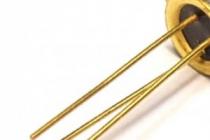
On many tuners, there are no protective diodes near the antenna connector (in this case, U7) - you can either solder them yourself (one to the ground, one from the ground - I, for example, soldered 1N4148), or leave it as it is, and do not touch the antenna with your bare hands and keep away from static electricity.
Software and API for working with RTL2832
rtl_sdr
Rtl_sdr is a driver that provides "inappropriate" use of data from TV tuners based on rtl2832. On Windows, you will have to replace the default tuner driver with WinUSB using the Zadig program.
Rtlsdr.dll is required by all SDR programs, and often this DLL is already shipped with software that uses the RTL2832.
Rtl_sdr can also be used via a console utility to test the tuner or merge a piece of air into a file:
Rtl_sdr -f 1575520000 -g 34 -s 2048000 out.dat
During further processing, you need to remember that the bytes of the I- and Q-streams go alternately in the file.
SDRSharp

What to listen to on the radio?
Radio communications in license-free bands
Civilian walkie-talkies that do not require registration in Russia operate at frequencies of 433 and 446 MHz. However, in Moscow it is difficult to hear Russian speech there. You can hear them immediately and without problems in SDRSharp, NFM modulation.
Since there are many channels, the SDRSharp AutoTuner Plugin is very useful - it automatically turns on the frequency at which the transmission is carried out, and thus you can listen to all radio channels at once.
To listen to radios at a frequency of 27 MHz, you need a tuner with an R820T chip or an external converter in the case of the E4000 (for example, Ham It Up v1.2 described earlier). The optimal antenna for 27 MHz already requires a more serious one, ~ 2.59 or ~ 1.23 m long.
Police radio conversations
The police in Moscow and in many other regions of Russia have switched to using digital radios operating in the APCO-25 (P25) standard. In P25, data is transmitted in digital form with compression and error correction codes - this allows you to increase the range of stable communication and cram more channels into the same radio frequency band. There is also the option of encrypting conversations, but regular police work without encryption.
A DSD decoder can be used to receive P25 radios. DSD expects audio data as input. You can redirect audio from SDRSharp to DSD using Virtual Audio Cable. DSD is very critical to the SDRSharp settings - I recommend setting the AF Gain to about 20-40%, it is possible to turn off the Filter Audio checkbox. If everything goes according to plan, decoded packets will run in the DSD window, and negotiations will be heard in the headphones. This scheme also works with the mentioned AutoTuner plugin in SDRSharp.
I suggest that readers find the frequencies on their own, since this information is not open.
Radio communications between aircraft and controllers
For historical reasons, radio communication in aviation uses amplitude modulation. Usually transmissions from aircraft are better heard than from controllers or weather informants on the ground. Frequency range - 117–130 MHz.
Receiving signals from automatic transmitters of aircraft ADS-B
ADS-B is used to ensure that both the controller and the pilot see the air situation. Each aircraft regularly transmits flight parameters at a frequency of 1090 MHz: flight name, altitude, speed, azimuth, current coordinates (not always transmitted).
We can also accept this data in order to personally observe the flights. Two popular ADS-B decoders for RTL2832 are ADSB# and RTL1090. I used ADSB#. Before starting, it is advisable to tune to 1090 MHz in SDRSharp, see if there is a signal and what frequency error is due to the inaccuracy of the crystal oscillator. This error must be compensated in the Front-end settings: Frequency correction (ppm). It must be remembered that the magnitude of this error may vary with the temperature of the receiver. The found correction must also be specified in the ADSB### window (after closing SDRSharp).
The optimal monopole antenna for 1090 MHz is only 6.9 cm long. Since the signal is very weak, it is highly desirable to have a dipole antenna mounted vertically with the same element length.
ADSB# decodes packets and waits for network connections from an air traffic client. As such a client, we will use adsbSCOPE .
After launching adsbSCOPE, you need to open the menu item Other -> Network -> Network setup, click on the adsb# button below, make sure that the server address is 127.0.0.1. Then you need to find your location on the map and execute the Navigation -> Set Receiver Location command. Then start connecting to ADSB#: Other -> Network -> RAW-data client active.
If everything is done correctly, then within a few minutes you will be able to see information about the aircraft (if, of course, they fly near you). In my case, with a monopole antenna, it was possible to receive signals from aircraft at a distance of about 25 km. The result can be improved by taking a better antenna (dipole or more complex), adding an additional input amplifier (preferably GaAs), using a tuner based on the R820T (at this frequency it has a higher sensitivity compared to the E4000).

Reception of long and short wave analog and digital radio stations
Before the advent of the Internet, HF radio stations were one of the ways to get news from the other side of the globe - short waves, reflected from the ionosphere, can be received far beyond the horizon. A large number of HF radio stations still exist today; they can be searched for in the range of ~ 8–15 MHz. At night in Moscow, I was able to hear radio stations from France, Italy, Germany, Bulgaria, Great Britain and China.
Further development - digital DRM radio stations: compressed audio with error correction + additional information is transmitted on short waves. You can listen to them with a decoder. The frequency range for searching is from 0 to 15 MHz. It must be remembered that a large antenna may be needed for such low frequencies.
In addition, you can hear amateur radio transmissions - at frequencies of 1810-2000 kHz, 3500-3800 kHz, 7000-7200 kHz, 144-146 MHz, 430-440 MHz and others.
Doomsday Radio - UVB-76
UVB-76 is located in western Russia, has been transmitting on 4.625 MHz since the early 1980s, and has a military purpose that is not entirely clear. On the air, voice code messages are transmitted from time to time. I managed to receive it on the RTL2832 with a converter and a 25-meter antenna lowered from the balcony.
GPS
One of the most unusual features is the reception of navigation signals from GPS satellites on a TV tuner. To do this, you need an active GPS antenna (with an amplifier). You need to connect the antenna to the tuner through a capacitor, and before the capacitor (from the side of the active antenna) - a 3 V battery to power the amplifier in the antenna.
Then you can either process the merged air dump with a matlab script - this may be interesting in order to study the principles of GPS operation - or use GNSS-SDR , which implements real-time decoding of GPS signals.
It would be difficult to receive a signal from GLONASS satellites in a similar way - there different satellites transmit at different frequencies, and all frequencies do not fit into the RTL2832 band.
Other applications and limits
The RTL2832 can be used to debug radio transmitters, eavesdrop on baby monitors and analog cordless phones, to parse communication protocols in radio-controlled toys, radio calls, car remotes, weather stations, systems for remote collection of information from sensors, electric meters. With a converter, you can read the code from the simplest 125 kHz RFID tags. Signals can be recorded for days, analyzed and then re-broadcast on transmission equipment. If necessary, the tuner can be connected to an Android device, Raspberry Pi or other compact computer to organize autonomous data collection from the radio.
You can take photos from weather satellites and listen to transmissions from the ISS - but this will require special antennas and amplifiers. Photos are decoded by the WXtoImg program.
It is possible to capture encrypted data transmitted by GSM phones (airprobe project) if frequency-hopping is disabled in the network.
The possibilities of SDR based on RTL2832 are still not unlimited: it does not reach Wi-Fi and Bluetooth in terms of frequency, and even if you make a converter, due to the fact that the captured frequency band cannot be wider than ~ 2.8 MHz, it is impossible will receive even one Wi-Fi channel. Bluetooth 1600 times per second changes the operating frequency in the range of 2400-2483 MHz, and it will not keep up with it. For the same reason, a full-fledged reception of analog television is impossible (there you need a received band of 8 MHz, with 2.8 MHz you can only get a black and white picture without sound). For such applications, more serious SDR receivers are needed: HackRF, bladeRF, USRP1 and others.
Nevertheless, everyone now has the opportunity to explore both analog and digital radio, touch satellites and aircraft!
It has been written and said repeatedly, How to make an SDR all-wave receiver and a TV tuner in one bottle? Yes, in fact, you don’t really need to do anything, with the exception of a civilian antenna on the roof for the desired range and a foil cable (to eliminate losses and interference). I had a very simple task, to make an Internet link to the Internet (such as an echo signal repeater) without buying expensive equipment for radio communication, since there is a dedicated server and IP, and the Internet works on fiber optics. And why not do it!? I started looking for information on the Internet. Some schemes there are heaped up or expensive equipment did not suit me in any way. Soldering and etching the boards is long and gimmicky - RF connector on the cable, please. Looks like a USB flash drive. The antenna there is complete shit, but I use .
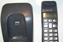
I understood only one thing, that the digital-to-analog receiver of the scanner should be based on a chip from the well-known company Realtek RTL2832U/ FC0013 and R820! Why is that? You ask. Because it is under it that the Internet is full of all sorts of software. Starting from TV-receivers of a digital HD-signal, to an SDR-all-wave amateur receiver (for all frequencies). Frequency range from 25 to 1700 megahertz! Step 300 hertz. Not bad? Entrance - I took a standard TV-mother - it is easier to solder (adapter from PL-dad, to TV-mother - pitgail). Built-in MPEG, DUB/SUB, DVB-T decoders. Modulation? All types: AM, FM, CW, USB, LSB, NFM, SSTV, WFM, NMT, AMPS, DAMPS, GSM, and others. You can listen to amateur. (Reception frequency 3666.6 kHz, LSB modulation). Not bad really. Listen to the neighbor's radiotelephone - no problem. It's easy to listen to ISS astronauts on 145800 mHz FM! Eavesdrop: Cops, Ministry of Emergency Situations, an ambulance, easily (but on some there is a specially coded signal). Listening to bugs is easy and simple! And other uses for this toy! While summer, and not winter is fierce - what would not do and do 2 in 1: SDR all-wave receiver and TV tuner.
 Since I live in Moscow, and I already have an antenna installed on the roof of the house, I perfectly receive about 100 HD TV channels for free in digital satellite format (I haven’t really figured it out yet, I set up a couple of Discovery and some other). And if you live outside the city, in the near suburbs? You can make a UHF antenna yourself, put it on the roof and point it to the source - that's satellite TV for free. About just radio - I’m silent in general, it is even transmitted in stereo! Well, the meaning of my invention is this: I transmit via a walkie-talkie at 446000 mHz (PMR), receive it on a TV tuner, transfer it from a computer to the Internet (to a link), the link transmits through the antenna on the air at 434000 MHz (LPD)! It turned out to be a kind of repeater from PMA to LPD - without buying a walkie-talkie and equipment. Tired, unfastened and put in his pocket. I arrived at the dacha, stuck it - you watch football, for example. Issue price: up to 2000 rubles + hands, free software. from "their" guys on the Market. "White" colors are no longer there, there are "black" ones. But I think it's not difficult to order. In general, the experiment was a success as I planned it.
PS: Some people ask about DVB-T2? Not yet and will not be in Russia! Now everywhere, the DVB-T (HD-quality) standard has just begun to broadcast. Yes, and the range is not rubber, it must be understood that all frequencies have already been painted.
They offered to review the DVB-T tuner. I would refuse because of the outdated broadcast format, but the device itself is too amusing. With the help of the tuner, you can receive and decode almost any signal in the range from 25 to 900 MHz. I decided to listen to the broadcast a little.
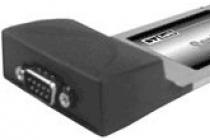
The tuner arrived in a gray box with no identification marks. Inside there is the device itself, a disk with software, a remote control and an antenna. All in plastic bags.
The tuner is slightly larger than a flash drive. The antenna is connected to the side. And through the holes the signal of the IR remote control is received.


We open immediately
The heart of the device is the RTL2832U chip, and the FC0012 chip is responsible for amplifying the RF signal. Instead of the latter, other microcircuits can be used, which affects the range of received frequencies, antenna sensitivity and requires the selection of appropriate drivers.

We are watching TV
Turning on and setting up is very simple. The tuner worked for me on Windows 7 and 10. The drivers and the TV receiver are on the CD, but you can find it on the Internet, if anything. I did not check it on the Linux family OS, but the performance in this environment is confirmed by comments on the Internet. Moreover, I launched the tuner on my smartphone in just a couple of clicks.
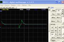
The Blaze HDTV Player program is taken as the basis for watching television channels. This is a paid application, although there is a serial number on the disc packaging. I took the latest version from the official site (demo version). Scanning the range takes about two minutes, after which I have a list of channels. In Kyiv for 2017, you can find 16 channels in the DVB-T range. (ERA | first national; Boutique; M2; PravdaTut; PlusPlus; NEWS 24; Rti; 100+; Channel 5; NewsOne; EU Music; Music Box; Rada; Sun; Nadia; KRT;). 
The same program can listen to the radio in the range of 88-108 MHz. With a confident reception, 28 stations were found. 
Unfortunately, but for a reliable signal reception, I had to take care of taking a laptop to the balcony with all the equipment. It would be nice to use a decent-sized antenna, but for this you have to get hold of an adapter from the used MCX connector to a regular antenna connector. Otherwise, you may end up with slides instead of a video stream. On the Internet, it is also recommended to touch the antenna less to avoid damage to the device by static.
I tried to collect statistics on signal reception in Kyiv. Near the Kharkovskaya metro station - the reception is bad. At the Demievskaya metro station - the reception is good. Near the Minsk metro station - reception is of average quality, a larger antenna is needed. Let me remind you that television broadcasting is also in the DVB-T2 range.
Alternative programs and drivers
First you need to attend to the replacement of device drivers. To do this, use the Zadig program, which can be found both along with the downloaded software or on the website. The above site shows the installation instructions in pictures. I’ll add on my own that to search for a device called RTL2838UHIDIR - in the program settings it would be nice to check the boxes next to “List all devices” and “Ignore Hubs or Composite Parents”.
Most of all I liked the SDRSHARP program. . I haven't explored all of its settings, but overall the ion is pretty functional. Changing the frequency is carried out by pressing the upper or lower part of the digits of the displayed current frequency. The type of received signal is selected automatically, depending on the range. But almost everything can be picked up by hand. With this program, I was able to receive a signal in the range of 21 MHz ... 
… up to 940 MHz. The FM band even displayed the station's RDS information. 
If you need to change the drivers to native ones from Realtek, then I found them here. Choose according to the chipset.
RTL2838U+ E4000, FC0012, FC0013= Treiber1.zip
RTL2838U+ R820T= Treiber2.zip
RTL2838U+ Noxon= Treiber3.zip
RTL2838U+ R828D= Treiber4.zip
Work via USB OTG on Android
For work, I needed a regular OTG cable. The tuner consumes quite a bit, about 0.7W, so I'm calm about the smartphone battery.

By going to the Play Market and specifying the phrase "RTL RDS" in the search, I found a lot of programs. I tested the first ones that came across. I scanned the range using the SDRTouch program (downloads the Rtl-sdr driver). And I watched TV through Aerial TV (downloads DVB-T driver). It turned out to be pretty stupid. 

Afterword
Despite the outdated DVB-T format, this tuner may well be needed both for watching TV channels and listening to the FM band, as well as for avid radio amateurs. The latter, I think, have already heard about such devices and their undocumented functions.Please forgive me for not checking the operation of the remote control.
The product was provided for writing a review by the store. The review is published in accordance with clause 18 of the Site Rules.
I plan to buy +40 Add to favorites Liked the review +43 +67