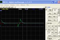
Not flat, a tailor's meter will help. And in the absence of a thin ruler, and if the card is not a pity to pierce, it is convenient to use a compass for measuring, preferably with two needles. Then it can be transferred to graph paper and measure the length of the segment on it.
Roads between two points are rarely straight. To measure the length of a curved line will help a convenient device - curvimeter. To use it, first rotate the roller to align the arrow with zero. If the curvimeter is electronic, it is not necessary to set it to zero manually - just press the reset button. While holding the roller, press it against the starting point of the line so that the notch on the body (it is located above the roller) points directly to this point. Then drive the roller along the line until the line is aligned with the end point. Read the statements. Please note that some curvimeters have two scales, one of which is graduated in centimeters and the other in inches.
Find the scale indicator on the map - it is usually located in the lower right corner. Sometimes this pointer is a segment of a calibrated length, next to which it is indicated what distance it corresponds to. Measure the length of this segment with a ruler. If it turns out, for example, that it has a length of 4 centimeters, and next to it it is indicated that it corresponds to 200 meters, divide the second number by the first, and you will find out that each card has a ready-made phrase instead of a segment, which may look, for example, as follows way: "There are 150 meters in one centimeter." Also, the scale can be specified as a ratio of the following form: 1:100000. In this case, you can calculate that a centimeter on the map corresponds to 1000 meters on the ground, since 100,000/100 (centimeters in a meter) = 1000 m.
Multiply the distance measured with a ruler or curvimeter, expressed in centimeters, by the number indicated on the map or calculated by the number of meters or kilometers in one centimeter. The result will be a real distance, expressed, respectively, in meters or kilometers.
Any map is a miniature image of some territory. The coefficient showing how much the image is reduced in relation to the real object is called the scale. Knowing it, you can determine the distance by map. For real-life paper-based maps, the scale is a fixed value. For virtual, electronic maps, this value changes along with a change in the magnification of the map image on the monitor screen.
Instruction
If yours is based, then find it, which is called a legend. Most often, it is in the marginal design. The legend must necessarily indicate the scale of the map, which will tell you, measured in distance along a given map will be in reality, on the ground. So, if the scale is 1:15000, then this means that 1 cm on the map is equal to 150 meters on the ground. If the scale of the map is 1:200000, then 1 cm plotted on it is equal to 2 km in reality
city or from one settlement to another, then your route will consist of straight segments. You will not move in a straight line, but along a route that runs along streets and roads.
In fact, the distance between the start and end points of your path will be longer than the distance measured between the start and end points of your path. To make measurements accurate, plot your route on the map in the form of short and long straight segments, determine their sum and find out from it the actual distance that you need to overcome.
To determine the distance on an electronic map, you can use one of the many geographic information programs that can be found on the Internet. There are specialized programs used by transport companies. By setting the initial and final destination, settlement, you will be able to get a map on which your route will be plotted and its total distance and the distance between the nodal points of the route will be indicated.
The distance on the map can be measured using the "Ruler" tool in the Google Earth and Yandex Maps geoinformation packages, the underlying basis for maps in which are space satellite images. Just enable this tool and click on the point that marks the beginning of your route and the one where you plan to end it. The distance value can be found in any given units of measurement.
The scale of a drawing, map, diagram or image is the ratio of the linear dimensions of objects reflected on them to the actual dimensions of these same objects on the ground or in nature. If this is a diagram, engineering drawing or map, then, as a rule, an indication of the scale is a mandatory requirement for such documents. But sometimes it happens that the scale is not known, so you need to determine it yourself.

Instruction
Just in case, check, maybe you just didn't notice this inscription. In and drawings, it must be indicated in the stamp. This may be an inscription of the full format "Scale 1:20" or the abbreviated "M 1:20". On topographic and diagrams, an indication of the scale is also an obligatory element of framing. It can be specified in the map title, which is located at the top or bottom. Sometimes the inscription displaying the scale is located in the text of the map legend or directly on it. Look carefully at the diagram or map.
If you did not find the indication of the scale on the diagram of a machine-building part or a construction plan, on which the dimensions of the part are indicated in or measurements in, then you can determine the scale yourself. Measure the dimensions on paper with a regular ruler in millimeters or fractions of a centimeter. Divide, indicated in the diagram and translated into millimeters or centimeters, by what you got when measuring. This will be the desired denominator of the scale of the drawing or plan.
Similarly, you can find out the scale of a map or topographic map. To do this, you need to carefully look at the map and identify a couple of characteristic objects located on the ground. For large-scale maps, these can be buildings, pipes of boiler houses. For maps and diagrams of small scales, you can use the tops of hills and mountains, forks in roads, and other characteristic points of relief and terrain. Use a ruler to measure the distance on the map between these characteristic objects.
If you have a map of the same territory with a known scale, then measure the distance between the same characteristic points on it and recalculate the scales. If there is no such map, then use the Yandex or Google mapping services. Find this area using satellite images, which are the basis of these services, and identify the same characteristic points on it that you found on a map or diagram. Select the "Ruler" tool, measure the distance in kilometers from satellite images and calculate the scale of your map using these data and the distance measured on the map.
To make the user feel comfortable when working on a computer, folder and file icons, inscriptions and other components of the system and the "Desktop" must be configured accordingly. To select and set the appropriate scale, you need to perform a series of actions.

Instruction
Open the Display Properties window. There are several ways to do this: through the Start menu, call the Control Panel, in the Appearance and Themes category, select the Display icon or any of the tasks. If the "Control Panel" is displayed in the classic view, click on the "Screen" icon immediately. Another way: in any free space on the "Desktop" right-click. In the drop-down menu, select "Properties" - the desired dialog box will open.
In the Display Properties dialog box that opens, click the Options tab. The scale of the image on the screen largely depends on the selected resolution. In the "Screen Resolution" category, use the "slider" to select the scale that suits you, and click the "Apply" button. When prompted by the system to confirm the changes, answer in the affirmative.
If you are not satisfied with the scale that can be selected in the described way, on the same tab, click on the "Advanced" button. In the additionally opened dialog box "Properties: Monitor connection module and [name of your video card]" go to the "General" tab. In the "Scale (number of dots per inch)" field, use the drop-down list to set the value to "Custom options". In the "Scale selection" window that opens, use the ruler or the drop-down list to set the scale you need. Click OK and Apply. If prompted, restart your computer.
On the Appearance tab of the Display Properties window, select a font size that is comfortable for your eyes. If there are not enough existing settings, click the "Advanced" button. Using the drop-down list in the "Element" section, select the element whose scale you want to change. Enter in the available fields the size of fonts you need, window control buttons, and so on. After making changes, press the OK button in the additional window, the Apply button in the properties window and close the window in the usual way.
In the era of the great geographical discoveries, travelers and discoverers faced the two most important tasks: measuring distances and determining their location on the earth's surface. The Greeks theoretically substantiated the solution of these problems, but they did not have sufficiently accurate tools and maps.
Interesting fact. When Spain and Portugal decided to agree on the division of the New World into spheres of influence, they could not draw the dividing line on the map accurately enough, because at that time they did not know how to determine the longitude of the place and the distance on the map. In this regard, there were constant disputes and conflicts between states.
Measuring distances using a degree network. To calculate distances on a map or globe, the following quantities can be used: the length of an arc of 1 ° meridian and 1 ° equator is approximately 111 km. For meridians, this is always true, and the length of an arc of 1 ° along the parallels decreases towards the poles (the magnitude of an arc at 1 ° parallel at the equator is 111 km, at 20 ° north or south latitude - 105 km, etc.). At the poles it is 0 (since a pole is a point). Therefore, it is necessary to know the number of kilometers corresponding to the length of 1 ° of the arc of each particular parallel. This number is written on each parallel on the map of the hemispheres. To determine the distance in kilometers between two points lying on the same meridian, calculate the distance between them in degrees, and then multiply the number of degrees by 111 km. To determine the distance between two points on the equator, you also need to determine the distance between them in degrees, and then multiply by 111 km.
Measuring distances with a scale. The length of a geographical feature can also be determined using the scale. The scale of the map shows how many times the distance on the map is reduced relative to the actual distance on the ground. Therefore, drawing a straight line (if you need to know the distance in a straight line) between two points and using a ruler to measure this distance in centimeters, you should multiply the resulting number by the scale value. For example, on a map at a scale of 1:100,000 (in 1 cm 1 km), the distance is 5 cm, i.e. on the ground this distance is 1 × 5 = 5 (km). You can also measure the distance on the map using a measuring compass. In this case, it is convenient to use a linear scale.
Measurement on the map of the length of a curved line (for example, the length of a river). For measurement, you can use compass, curvimeter or thin wet thread. Suppose the measurement is carried out on a map of scale 1: 5,000,000 (in 1 cm 50 km). The measuring compass is given a small solution (2-3 mm) in order to be able to measure the small bends of the river, and they walk along the river, counting the steps. Then, multiplying the size of the compass opening (for example, 3 mm) by the number of steps (suppose 49), they find the total length of the river on the map:
3 mm × 49 = 147 mm = 14.7 cm.
Thus, the length of the river will be equal to 50 km × 14.7 = 735 km.
Can you measure the length of a river? curvimeter - a special device for measuring the lengths of curved lines on maps and plans. The curvimeter wheel is rolled along a curved line (rivers, roads, etc.), and the curvimeter counter counts the revolutions, indicating the required line length.
You can measure the length of the curve with a wet thin thread. It is laid out along all the meanders of the river. Then, straightening the thread without strong tension, measure its length in centimeters, and by the scale determine the length of the river in reality.
If the length of a river is measured on a small-scale map, then the result obtained is less than the actual length of this river. This is due to the fact that it is impossible to show all the small bends of its channel on small-scale maps. Topographic maps, on the other hand, give more opportunity to reflect all the bends of the channel, besides, the distortions on them are very small. Therefore, the most accurate measurement results can be obtained from topographic maps.
Odometer
When developing a route for a hike, an important criterion is its length. Depending on this, the complexity and duration of the upcoming route are calculated, the time required to complete it, the required average speed, the supply of water and food, and the minimum acceptable degree of preparedness of future participants is determined. Ways and methods of developing the route itself may be different, but everything depends on the distance that you are ready to cover in the time allotted for its passage. Much will depend on the accuracy of your measurements and calculations, in particular, whether you will have time for the planned return train or whether you will have to look for a place in a hotel or sit on the platform waiting for the morning train.
There are many tools and methods for measuring distances on a map, but not all of them are equally applicable and convenient for accurately measuring the length of future routes along winding roads.
As a means for measuring segments on the map, you can use the usual ruler or compass. But as you might guess, all these devices are designed to measure straight segments, and a bicycle route is rarely a set of straight lines, unless you ride through the city streets. When measuring a route passing along winding roads and paths using linear tools, you will certainly encounter the need for additional calculations, including determining the magnitude of the error of your measurements, since the usual smooth bend of the road when measured with a ruler will look like a polyline consisting of many short straight lines segments. At the same time, the longer and more winding the route, the greater the error will be allowed in your measurements and the more approximately the total length of the route will be determined, especially if you use a small-scale map to plot the route.
More accurate results can be obtained when using a thread with transverse strokes-divisions previously applied to it using the same ruler, corresponding to a centimeter scale. However, in this case, the accuracy of the measurement will directly depend on your accuracy and patience when laying out the thread on the surface of the card.
Fortunately, for a long time there has been a special simple device designed just for taking measurements on a map of both straight and winding segments called a curvimeter. Curvimeter (from Latin curvus - curve and ... meter), a device for measuring the lengths of segments of curves and winding lines on topographic plans, maps and graphic documents.
The curvimeter is made with circular and rectilinear scales. Each type of curvimeter is available in two versions: with a fixed dial and a movable hand or index; with movable dial and fixed index. To measure the length of a line, the Curvimeter wheel is rolled along this line. The distance measured by the Curvimeter in one revolution corresponds to a scale length of 100 cm. The measurement error of a straight line segment with a length of at least 50 cm is not more than 0.25 cm.
Curvimeter mechanical (shown in the figure) has a metric and inch scale. The division value of the metric scale corresponds to 1 cm, inch to 0.05 inches. The measurement error of a segment with a length of 50 cm does not exceed 0.5%.
Thus, when using a curvimeter, you can measure the winding section of the route you need at the lowest cost and with the greatest accuracy. However, here you should also remember a few simple rules for measuring the route using this device.
First, when measuring the total length of a route, do not try to measure the entire length of the route at once from start to finish. It is better to measure in segments - from one important landmark to another. And the point is not at all that you may not have enough length of the scale. It’s just that with an increase in the length of the measured segment, the degree of measurement error increases, an uncomfortable position, fatigue or hand trembling can also affect the accuracy of measurements in a bad way.
Second, use a larger scale map whenever possible. In practice, a map with a scale of 1:50,000 (five hundred meters) or 1: 100,000 (kilometer) will do just fine. Just do not be lazy to carefully trace all the bends of the road with a curvimeter.
Thirdly, do not be too lazy to measure each segment several times. This way you will avoid accidental error. If you use a conventional mechanical curvimeter, and not an electronic analog that allows you to measure with tenths and even thousandths, determining by eye the remaining “tail” by eye, which is very important on maps with a scale of less than 1:100,000, do not strive to always round in one direction ( greater or less) use at least approximate tenths.
Fourthly, in the segments between the main landmarks, do not be too lazy to separately measure the distances to secondary landmarks along the route, for example, a bridge over a canal, a crossroads, a deep ravine, etc. Thus, as mentioned above, you will be able to constantly monitor your location on the route and have an accurate idea of the distance remaining to the finish line even without a GPS receiver, but only with the help of a map with distances to landmarks plotted on it.
When plotting the results of measurements on a map, it seems convenient to use the fractional record A / B., where A is the distance from the previous landmark, and B is the distance from the starting point of the route. This method allows you to easily navigate in space without unnecessary mathematical calculations. This is relevant, for example, when you need to inform your fellow travelers, especially those who like to get ahead of the main group, the exact distance to the landmark near which you need to turn, wait for the group, etc. In addition, if you are on any of the segments of the route made radial sorties or accidentally made an unplanned detour, for example, bypassing a blurred section of the road, you do not have to make adjustments to pre-applied marks on the map, rewrite them, or constantly keep in mind the number of “extra” kilometers that you will have to constantly adjust for.
An example of measuring and plotting its results on a map:
Start (0/0) - turn right, exit from the asphalt highway to a dirt road (3/3) - bridge over the river (2/5) - Dubki village (7/13) - Lesnoy village (14/27) - bridge over creek (5/32) - intersection with asphalt highway (8/40) - railway station Terminal (10/50).
And a few words about the variety of forms and varieties of curvimeters that are presented today on the Russian market.
 As mentioned above, there are two main types of curvimeters: mechanical and electronic.
In the device of mechanical curvimeters, regardless of the specific model, there are no special fundamental differences, with the exception of the type of scale (rectilinear and circular) and the principle of displaying the measurement results (with a fixed dial and a movable hand or index; with a movable dial and a fixed index). As a rule, this is a plastic device weighing about 50 grams of rather modest size. For example, the Russian-made KU-A curvimeter shown in the figure has dimensions of 50 × 20 × 100 (in a case).
This curvimeter has been produced in our country for more than a decade in its unchanged form, except now without the USSR quality mark, and was included in the mandatory list of items as part of the officer's tablet. It was standardized back in Soviet times and complies with TU 25-07-1039-74. The cost of this copy is about 500 rubles.
The curvimeter of the Swedish company is arranged in approximately the same way. Silva. However, the fixed dial has more complex markings for measurements at eight scales.

The cost of such a curvimeter is about 1000 rubles.
Another sample of a Russian-made mechanical curvimeter, made in the form of a key fob and equipped with an additional compass.

The dial of the curvimeter has scales for maps at a scale of 1:5000, 1:20000 and 1:50000. as well as a metric scale, the division value of which corresponds to 1 centimeter.
Its cost is 120 rubles.
another sample with survive.cat

Distance measurement in mm, cm, NM and km.
– Measuring range: 10 m (actual size)
- Features: scale setting
— Metal wheel for measurements
Diameter 4.5cm
Length 9.7cm
Materials: plastic, steel, plastic glass.
price 215.00 rub.
In general, mechanical curvimeters have several main advantages:
- simplicity of design and use;
- the absence of electronic circuits and other complex elements, suggests the possibility of its use in any climatic, weather and temperature conditions;
- complete energy independence due to the lack of batteries as such;
- good impact resistance and the impossibility of putting it out of action as a result of water procedures.
All of the above makes the mechanical curvimeter the most suitable for use in the field. The main and probably the only drawback of such a curvimeter is the need to determine tenths of the division value “by eye”.
Now let's turn to the variety of electronic curvimeters. Here, the cost of one copy ranges from three hundred to five thousand rubles, depending on the complexity of the device and the number of basic and additional functions in it. As in the production of many other electronic devices, manufacturers of electronic curvimeters rarely avoid the temptation to endow it with a host of additional features, both useful and not very.
For example, one of the simplest electronic curvimeters of the same Swedish company Silva, entitled Silva Digital Map Measurer made in the form of a key fob, and in addition to performing the main function - measuring the distance on the map, it is additionally equipped with:
Calculator;
- mini flashlight;
- compass.
Its cost is about >2000 rubles.
A much more sophisticated high-precision curvimeter made in the USA called "Scal Master II", designed to perform complex graphic measurements and calculations, has its own software, the ability to connect to a personal computer and has 91 architectural and engineering functions.

This unit handles 50 Anglo-American values (feet, inches, etc.) and 41 metric values, allowing you to work with any maps and drawings. You can enter the most commonly used type of measurement and the instrument will automatically translate scale measurements. Has the ability to save data. It has the ability to connect to a computer using the PC-Interface Kit. Compatible with Windows. Works with Excel, Lotus.
Technical characteristics of the curvimeter Scale Master II:
Size: 182×41×15mm
Weight: 54g
Wheel material: solid polymer
Email power supply: 2×3 Volt - lithium
Service life: up to 400 hours
Automatic shutdown: 5 min.
Number of buttons: 12
Operating temperatures: 0 - 55O C
Display size: 19×64 mm.
The cost of such a device + Kit for connecting to a PC -> 11,000 rubles
Summarizing information about electronic curvimeters, we can conclude that their use in the field, especially more complex analogues, is associated with some difficulties. Exposure to external influences such as cold and moisture, dependence on the presence of batteries and a significantly lower impact resistance suggest the use of such a device primarily in greenhouse conditions of urban premises for the preliminary development of routes. At the same time, the indisputable advantage of the electronic curvimeter will be the maximum accuracy of measurements, and the possibility of their immediate processing, for example, conversion to kilometers, depending on the previously set scale.
Thanks to the "corporation of good" we can easily find a comfortable road from point "A" to point "B". But did you know that Google Maps also allows you to measure the simple distance between two points in a straight line?
1. Open the official Google Maps website on your PC or Mac.
2. Find the starting point of your route and click on it with the right mouse button.
3. In the menu that opens, select the Measure distance item.

4. Click on the end point of your route or the next point. The distances will be indicated next to the ruler.


Note: if you need to reposition a point, drag it. If you need to delete a measurement, just click on the point.
How to measure the distance between two points in Google Maps web version
Distance measurement is also available in the Google Maps apps for Android and iOS. And there, and there the measurement process works almost the same. Let's look at it using an example of a proprietary solution for iOS:
1. Open the Google Maps app on your iPhone or iPad.
2. Find the first point and touch it with your finger to set the red pin.
3. At the bottom of the map, click on the name of the place you marked.
4. Select Measure Distance from the drop down menu.

5. Aim the black crosshairs at point "B" of your route by moving your finger on the map.

6. The distance (in our case in kilometers) will be displayed at the bottom left of the screen.
You can cancel the measurement by clicking on the Back arrow in the upper left corner of the screen or by clicking on the ellipsis menu - Clear.
Note: if you need a complex measurement from several points, just continue moving the crosshairs after step 6. Point it at the third waypoint - and get the distance in km already to it, taking into account the previous two.

According to yablyk
1.1 Map scales
map scale shows how many times the length of the line on the map is less than the corresponding length on the ground. It is expressed as a ratio of two numbers. For example, a scale of 1:50,000 means that all terrain lines are shown on the map with a reduction of 50,000 times, i.e. 1 cm on the map corresponds to 50,000 cm (or 500 m) on the ground.
Rice. 1. Registration of numerical and linear scales on topographic maps and city plans
The scale is indicated under the lower side of the map frame in numerical terms (numerical scale) and in the form of a straight line (linear scale), on the segments of which the corresponding distances on the ground are signed (Fig. 1). The scale value is also indicated here - the distance in meters (or kilometers) on the ground, corresponding to one centimeter on the map.
It is useful to remember the rule: if you cross out the last two zeros on the right side of the ratio, then the remaining number will show how many meters on the ground correspond to 1 cm on the map, that is, the scale value.
When comparing several scales, the larger one will be the one with the smaller number on the right side of the ratio. Let's assume that there are maps of 1:25000, 1:50000 and 1:100000 scales for the same area. Of these, the 1:25000 scale will be the largest, and the 1:100,000 scale will be the smallest.
The larger the scale of the map, the more detailed the terrain is shown on it. With a decrease in the scale of the map, the number of terrain details applied to it also decreases.
The detail of the image of the area on topographic maps depends on its nature: the less details the area contains, the more fully they are displayed on maps of smaller scales.
In our country and many other countries, the main scales of topographic maps are: 1:10000, 1:25000, 1:50000, 1:100000, 1:200000, 1:500000 and 1:1000000.
The cards used in the troops are divided into large scale, medium scale and small scale.
| map scale | Card name | Map classification | |
| scale | by main purpose | ||
| 1:10 000 (in 1 cm 100 m) | ten thousandth | large scale | tactical |
| 1:25 000 (in 1 cm 250 m) | twenty-five thousandth | ||
| 1:50 000 (in 1 cm 500 m) | five thousandth | ||
| 1:100,000 (in 1 cm 1 km) | hundred thousandth | medium scale | |
| 1:200,000 (in 1 cm 2 km) | two hundred thousandth | operational | |
| 1:500,000 (in 1 cm 5 km) | five hundred thousandth | small scale | |
| 1:1 000 000 (in 1 cm 10 km) | millionth | ||
1.2. Measurement on a map of straight and winding lines
To determine the distance between points of the terrain (objects, objects) on the map, using a numerical scale, it is necessary to measure the distance between these points in centimeters on the map and multiply the resulting number by the scale value.
For example, on a map with a scale of 1:25000, we measure the distance between the bridge and the windmill with a ruler (Fig. 2); it is equal to 7.3 cm, multiply 250 m by 7.3 and get the desired distance; it is equal to 1825 meters (250x7.3=1825).
 Rice. 2. Determine the distance between points on the map using a ruler.
A small distance between two points in a straight line is easier to determine using a linear scale (Fig. 3). To do this, it is enough to apply a compass-meter, the solution of which is equal to the distance between given points on the map, to a linear scale and take a reading in meters or kilometers. On fig. 3 the measured distance is 1070 m.
 Rice. 3. Measurement on a map of distances with a compass-meter on a linear scale
 Rice. 4. Measurement on the map of distances with a compass-meter along winding lines
Large distances between points along straight lines are usually measured using a long ruler or measuring compass.
In the first case, a numerical scale is used to determine the distance on the map using a ruler (see Fig. 2).
In the second case, the “step” solution of the measuring compass is set so that it corresponds to an integer number of kilometers, and an integer number of “steps” is set aside on the segment measured on the map. The distance that does not fit into an integer number of “steps” of the measuring compass is determined using a linear scale and added to the resulting number of kilometers.
In the same way, distances are measured along winding lines (Fig. 4). In this case, the "step" of the measuring compass should be taken as 0.5 or 1 cm, depending on the length and degree of sinuosity of the measured line.
 Rice. 5. Distance measurements with a curvimeter
To determine the length of the route on the map, a special device is used, called a curvimeter (Fig. 5), which is especially convenient for measuring winding and long lines.
The device has a wheel, which is connected by a gear system with an arrow.
When measuring the distance with a curvimeter, you need to set its arrow to division 99. Keeping the curvimeter in a vertical position, guide it along the line being measured, without tearing it off the map along the route so that the scale readings increase. Bringing to the end point, count the measured distance and multiply it by the denominator of the numerical scale. (In this example 34x25000=850000, or 8500 m)
1.3. The accuracy of measuring distances on the map. Distance corrections for slope and tortuosity of lines
Map Distance Accuracy depends on the scale of the map, the nature of the measured lines (straight, winding), the chosen measurement method, the terrain and other factors.
The most accurate way to determine the distance on the map is in a straight line.
When measuring distances using a measuring compass or a ruler with millimeter divisions, the average measurement error on flat terrain usually does not exceed 0.7-1 mm on the map scale, which is 17.5-25 m for a 1:25000 scale map, scale 1:50000 - 35-50 m, scale 1:100000 - 70-100 m.
In mountainous areas, with a large steepness of the slopes, errors will be greater. This is explained by the fact that when surveying the terrain, it is not the length of the lines on the surface of the Earth that is plotted on the map, but the length of the projections of these lines on the plane.
For example, With a slope slope of 20 ° (Fig. 6) and a distance on the ground of 2120 m, its projection on the plane (distance on the map) is 2000 m, i.e. 120 m less.
It has been calculated that at an inclination angle (slope slope) of 20°, the obtained result of measuring the distance on the map should be increased by 6% (add 6 m per 100 m), by 15% at an inclination angle of 30°, and by 23 at an angle of 40°. %.
 Rice. 6. Projection of the slope length on a plane (map)
When determining the length of the route on the map, it should be borne in mind that the distances along the roads, measured on the map using a compass or curvimeter, in most cases are shorter than the actual distances.
This is explained not only by the presence of descents and ascents on the roads, but also by some generalization of the meanders of the roads on the maps.
Therefore, the result of measuring the length of the route obtained from the map should be multiplied by the coefficient indicated in the table, taking into account the nature of the terrain and the scale of the map.
1.4. The simplest ways to measure areas on a map
An approximate estimate of the size of the areas is made by eye on the squares of the kilometer grid available on the map. Each square of the grid of maps at scales 1:10000 - 1:50000 on the ground corresponds to 1 km2, a square of the grid of maps at a scale of 1 : 100000 - 4 km2, to the square of the grid of maps at a scale of 1:200000 - 16 km2.
Areas are measured more accurately palette, which is a sheet of transparent plastic with a grid of squares with a side of 10 mm applied to it (depending on the scale of the map and the required measurement accuracy).
Having superimposed such a palette on the measured object on the map, it first calculates the number of squares that completely fit inside the contour of the object, and then the number of squares intersected by the contour of the object. Each of the incomplete squares is taken as half a square. As a result of multiplying the area of one square by the sum of the squares, the area of \u200b\u200bthe object is obtained.
Using squares of scales 1:25,000 and 1:50,000, it is convenient to measure the areas of small areas with an officer's ruler, which has special rectangular cutouts. The areas of these rectangles (in hectares) are indicated on the ruler for each hart scale.
2. Azimuths and directional angle. Magnetic declination, meridian convergence and direction correction
true azimuth(Ai) - horizontal angle measured clockwise from 0° to 360° between the north direction of the true meridian of a given point and the direction to the object (see Fig. 7).
Magnetic azimuth(Am) - horizontal angle measured clockwise from 0e to 360° between the north direction of the magnetic meridian of the given point and the direction to the object.
Directional angle(α; DN) - horizontal angle measured clockwise from 0° to 360° between the north direction of the vertical grid line of the given point and the direction to the object.
Magnetic declination(δ; Sk) - the angle between the northern direction of the true and magnetic meridians at a given point.
If the magnetic needle deviates from the true meridian to the east, then the declination is east (taken into account with the + sign), if the magnetic needle deviates to the west, it is western (taken into account with the - sign).
 Rice. 7. Angles, directions and their relationship on the map
convergence of meridians(γ; Sat) - the angle between the northern direction of the true meridian and the vertical line of the coordinate grid at a given point. When the grid line deviates to the east, the approach of the meridian is east (taken into account with the + sign), when the grid line deviates to the west, it is western (taken into account with the - sign).
Direction correction(PN) - the angle between the northern direction of the vertical grid line and the direction of the magnetic meridian. It is equal to the algebraic difference between the magnetic declination and the approach of the meridians:
![]()
3. Measurement and construction of directional angles on the map. Transition from directional angle to magnetic azimuth and vice versa
On the ground using a compass (compass) measure magnetic azimuths directions, from which they then move to directional angles.
On the map on the contrary, they measure directional angles and from them they pass to the magnetic azimuths of directions on the ground.
 Rice. 8. Changing the directional angles on the map with a protractor
Directional angles on the map are measured with a protractor or a chordogonometer.
Measurement of directional angles with a protractor is carried out in the following sequence:
- the landmark on which the directional angle is measured is connected by a straight line to the standing point so that this straight line is greater than the radius of the protractor and intersects at least one vertical line of the coordinate grid;
- combine the center of the protractor with the intersection point, as shown in Fig. 8 and count the value of the directional angle along the protractor. In our example, the directional angle from point A to point B is 274° (Fig. 8, a), and from point A to point C - 65° (Fig. 8, b).
In practice, it often becomes necessary to determine the magnetic AM from a known directional angle ά, or, conversely, the angle ά to a known magnetic azimuth.
Transition from directional angle to magnetic azimuth and vice versa
The transition from the directional angle to the magnetic azimuth and back is performed when it is necessary to find the direction on the ground using a compass (compass), the directional angle of which is measured on the map, or vice versa, when it is necessary to plot the direction on the map, the magnetic azimuth of which is measured, on the terrain with compass.
To solve this problem, it is necessary to know the magnitude of the deviation of the magnetic meridian of a given point from the vertical kilometer line. This value is called the directional correction (PN).

 Rice. 10. Determination of the correction for the transition from the directional angle to the magnetic azimuth and vice versa
The direction correction and its constituent angles - the convergence of the meridians and the magnetic declination - are indicated on the map under the south side of the frame in the form of a diagram that looks like the one shown in fig. 9.
convergence of meridians(g) - the angle between the true meridian of the point and the vertical kilometer line depends on the distance of this point from the axial meridian of the zone and can have a value from 0 to ±3°. The diagram shows the average convergence of meridians for a given sheet of the map.
Magnetic declination(d) - the angle between the true and magnetic meridians is indicated on the diagram for the year of surveying (updating) the map. The text placed next to the diagram provides information about the direction and magnitude of the annual change in magnetic declination.
To avoid errors in determining the magnitude and sign of the direction correction, the following method is recommended.
Draw an arbitrary direction OM from the top of the corners in the diagram (Fig. 10) and designate the directional angle ά and the magnetic azimuth Am of this direction with arcs. Then it will immediately be seen what the magnitude and sign of the direction correction are.
If, for example, ά = 97°12", then Am = 97°12" - (2°10"+10°15") = 84°47 " .
4. Preparation on the data map for movement in azimuths
Movement in azimuths- this is the main way of orienting in terrain poor in landmarks, especially at night and with limited visibility.
Its essence lies in maintaining on the ground the directions given by magnetic azimuths, and the distances determined on the map between the turning points of the intended route. The directions of movement are maintained with the help of a compass, distances are measured in steps or on a speedometer.
The initial data for movement in azimuths (magnetic azimuths and distances) are determined on the map, and the time of movement is determined according to the standard and drawn up in the form of a diagram (Fig. 11) or entered in a table (Table 1). Data in this form is issued to commanders who do not have topographic maps. If the commander has his own work map, then he draws up the initial data for movement in azimuths directly on the work map.
 Rice. 11. Scheme for movement in azimuth
The route of movement in azimuths is chosen taking into account the terrain, its protective and camouflage properties, so that it provides a quick and covert exit to the specified point in a combat situation.
The route usually includes roads, clearings and other linear landmarks that make it easier to maintain the direction of movement. Turning points are chosen from landmarks that are easily identifiable on the ground (for example, tower-type buildings, road intersections, bridges, overpasses, geodetic points, etc.).
It has been experimentally established that the distances between landmarks at the turning points of the route should not exceed 1 km when driving during the day on foot, and when driving by car - 6–10 km.
For movement at night, landmarks are marked along the route more often.
In order to provide a secret exit to the specified point, the route is planned along hollows, vegetation massifs and other objects that provide movement masking. It is necessary to avoid movement on the crests of hills and open areas.
The distances between the landmarks chosen on the route at the turning points are measured along straight lines using a measuring compass and a linear scale, or perhaps more precisely, with a ruler with millimeter divisions. If the route is planned along a hilly (mountainous) area, then a relief correction is introduced into the distances measured on the map.
Table 1
5. Compliance with regulations
| no. | Name of the standard | Conditions (order) for fulfilling the standard | Category of trainees | Time estimate | ||
| "excellent" | "hor." | "ud." | ||||
| 1 | Determining the direction (azimuth) on the ground | A direction azimuth (landmark) is given. Indicate the direction corresponding to the given azimuth on the ground, or determine the azimuth to the specified landmark. The time to fulfill the standard is counted from the setting of the task to the report on the direction (azimuth value). Compliance with the standard is assessed |
Serviceman | 40 s | 45 s | 55 s |
| 5 | Preparing data for moving along azimuths | On the M 1:50000 map, two points are indicated at a distance of at least 4 km. Study the terrain on the map, outline the route of movement, select at least three intermediate landmarks, determine the directional angles and the distances between them. Draw up a scheme (table) of data for movement along azimuths (translate directional angles into magnetic azimuths, and distances into pairs of steps). Errors that reduce the rating to "unsatisfactory":
The time to fulfill the standard is counted from the moment the card is issued to the presentation of the scheme (table). |
officers | 8 min | 9 min | 11 min |
This article was produced by our experienced team of editors and researchers who reviewed it for accuracy and completeness.
Number of sources used in this article: . You will find a list of them at the bottom of the page.
A topographic map is a two-dimensional map that depicts a three-dimensional area, while the height of the earth's surface is indicated using contour lines. As in the case of any other map, the distance between two points on a topographic map is measured along a straight line connecting them, as if a bird flies between these points. This is done first, and only then the surface topography and other terrain features that may affect the overall length of the route are taken into account. Learn how to measure distance along a straight line.
Steps
Measuring distance on a linear scale
- Take a strip of paper long enough to cover the distance between the points you are interested in. Note that this method is best for measuring relatively short linear distances.
- Press a strip of paper against the map and try to mark the location of two points on it as accurately as possible.
-
Attach a strip of paper to a linear scale. Find a linear scale on a topographic map - as a rule, it is located in the lower left corner of the map. Attach a strip of paper with two marks to it to determine the distance between them. Use this method to measure small distances that fit on a linear scale.
Determine b O most of the distance on the main scale. Attach a strip of paper to the scale so that the right mark coincides with the whole number on the scale. In this case, the left label should be on an additional scale.
- The point of the main scale, in which the right label will appear, is determined by the condition that the left label must fall on the additional scale. In this case, it is necessary to combine the right label with an integer on the main scale.
- The integer corresponding to the right label on the main scale indicates that the measured distance is at least so many meters or kilometers. The rest of the distance can be more accurately determined by the additional scale.
-
Go to the additional scale, on which the base of the scale is divided into parts. Determine the length of the smaller part of the distance on the additional scale. The left mark will match the integer on the secondary scale - this number should be divided by ten and added to the distance determined on the main scale.
Measuring distance on a numerical scale
-
Mark the distance on a strip of paper. Place a strip of paper with a straight edge on the map and align that edge with the points you want to measure. Mark "Point A" and "Point B" on paper.
- Press the strip of paper against the card and do not bend it to get the most accurate results possible.
- If desired, you can use a ruler or measuring tape instead of paper. In this case, write down the measured distance between the dots in millimeters.
-
Measure the distance with a ruler. Attach a ruler or measuring tape to the paper and determine the distance between the two marks. Use this method to measure large distances that are outside the linear scale, or if you want to calculate the distance as accurately as possible.
- Try to determine the distance to the nearest millimeter.
- Find the scale at the bottom of the map. Here the ratio of lengths should be given, as well as a segment (linear scale) with centimeters plotted on it. As a rule, for convenience, the scale is chosen in whole numbers, for example, 1 centimeter = 1 kilometer.
-
Calculate the distance along a straight line. To do this, use the distance measured on the map in millimeters and the numerical scale, which is the ratio of lengths. Multiply the measured distance by the scale denominator.
-
Attach a strip of paper to the map and mark the points on it. Lay a strip of paper with a straight edge over the card. Align this edge simultaneously with the first (“Point A”) and the second (“Point B”) points that you want to measure the distance between, and mark on paper the location of these points.