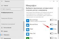
RS232 is the definition of a standard that describes the interface used to connect data devices to a computer. The standard was first developed and adopted in the 60s of the twentieth century, but still has not lost its relevance. In 1991, its final revision, EIA/TIA-232-E, was prepared and is still in use today. The first company to use it in their computers was IBM, and nowadays RS232 is part of the structure of almost every personal computer. It is called the Communication port (COM port).
With RS232 standard a connection is provided between two devices: a computer (Data Terminal Equipment) and the data transmission equipment itself (Data Communications Equipment). Knowledge of these designations in an abbreviated form (DTE and DCE) is important to know in order to be able to deal with technical description and the order of connection and operation specific devices. Any self-respecting programmer is familiar with this standard.
DCE is most often a modem, but RS232 is also suitable for connecting other peripherals, such as a printer or mouse. Data transmission is carried out using wires. The hardware implementation of the standard refers to the fact that it always works on a PC, regardless of which operating system is installed on the computer. Programs can interact with the COM port by absolutely any means: using BIOS functions, through components operating system, through the direct code of the microprocessor, as well as through the components of languages top level. RS232 connects a computer to local network internet via Ethernet technology, and is also included in the information transfer system between a personal computer and industrial equipment.
In a word, standard RS232 is universal. But, despite this, it was replaced by other ways of connecting a computer to peripheral devices. We are talking, for example, about USB ports.
What is the difference between RS-232 and USB
The standard differs in ease of programming from USB, therefore, to implement a data exchange protocol over this more modern technology it was difficult enough. Both specialists and radio amateurs were actively involved in this.
The indisputable advantage of RS-232 is the fact that the maximum speed that is possible when exchanging through this interface is unlikely to be blocked by modern wireless devices connections. IN Lately there is a tendency to limit the power of radio transceivers that are used to exchange data over wireless connection. This does not allow increasing the information transfer rate, which today is a maximum of 9600 baud, and with the RS-232 interface - 115,200 baud.
Used signal levels
The RS-232 standard is characterized by two signal levels - 0 and 1. Logic 1 and 0 correspond to different voltage levels - negative and positive, respectively. When passing through the cable, the signal can not only be distorted, but also weakened. As the length of the cable increases, the attenuation increases. This can be easily explained by the electrical capacitance of the cable. Therefore, its length is usually limited to 17 meters in order to provide sufficient maximum load capacitance, which is 2500 pF. In this case, the data transfer rate will be 9600 bits per second. In principle, it is possible to achieve normal operation of the cable and connection even with a much longer cable length. Experts say that they managed to increase the unshielded cable twice, and the shielded cable - five times. In each specific case, a different level of electromagnetic oscillations is taken into account.
To ensure the connection, a cable connected according to the "contact to contact" scheme is required. Null-modem cable types are mainly used, in which crossed wires are located.
Transfer of information
The RS232 standard is considered a serial interface because the stream is transmitted on a first-in, first-out basis. The information flow is transmitted sequentially, bit by bit. When no information is being transmitted over the cable, the line goes into a logic 1 state.
Where RS232 standard is used
The scope of the RS232 standard is quite wide. First of all, it is highly specialized equipment, sensors, built-in appliances, and measuring instruments. Despite the fact that you can still find it in some computers, RS232 has practically no prospects for the future. There are still such echoes of the past in some economic and industrial sectors. The standard is gradually being classified as obsolete, it is being used less and less in modern devices processing and transmission of information.
The interaction of various devices with computer technology through the RS-232 interface can be found at enterprises that are engaged in serial testing and conduct scientific experiments. This is due to the exceptional need to automate the processes of obtaining, collecting and analyzing data and results.
RS-232 standard actively used in multifunctional measuring instruments, for example, an electricity meter equipped with additional function control over costs according to established tariffs. Data is read and transmitted via the RS-232 interface.
In the Orion system, the RS-232 interface is used to connect the S2000/S2000M control and management console to the COM port of the computer with the Orion/Orion Pro workstation installed on it.
In systems that allow operation under the control of AWS "Orion" / "Orion Pro" without redundancy with the console "S2000" / "S2000M" (for example, in systems burglar alarm or access control), the RS-232 interface is used to connect the interface converter "S2000-PI" or "PI-GR" to the COM port of the computer. In turn, devices of the Orion system are connected to the converter via the RS-485 interface. RS-232 has the following limitations: maximum length is 15 m and point-to-point connection only, i.e. It is not possible to directly connect several consoles to one COM port.
In the simplest case, only one remote control is connected to the computer. This scheme is shown in fig.
The disadvantage of this scheme is the lack of galvanic isolation between the devices and the computer. The scheme for connecting the remote control to a computer using the S2000-PI interface repeater, which provides galvanic isolation, is shown in fig.

ATTENTION! To avoid galvanic coupling between the computer and devices, the remote control, repeater and devices must not be connected to the same power source. Power supply to the remote control and S2000-PI must be supplied from a separate source.
The remote must be assigned network address, and the “COMPUTER” mode is set to work via the RS-232 interface.
Using RS-232/RS-485 interface converters with automatic transmission/reception switching (for example, S2000-PI), you can connect several consoles to one computer COM port. One converter should be connected to the computer's COM port, the rest - to the consoles via the RS-232 interface, and then the converters should be connected via the RS-485 interface (see the diagram in the figure above). Besides, converters will provide galvanic isolation of the computer from panels and devices.
To work via the RS-232 interface, each remote control must be assigned a unique network address and the “COMPUTER” mode.
When using the Orion workstation, up to 127 devices can be connected to one COM port. Or it will be one "S2000" / "S2000M" remote control and up to 126 devices, the scheme is as in the figures above. Or it will be several consoles with connected devices, as in fig.

In this case, the total number of consoles and devices should not exceed 127. In such a system, all devices and consoles must have unique network addresses from 1 to 127, i.e. addresses of devices connected to different consoles must not overlap.
When using the Orion Pro workstation, each COM port can connect either up to 127 devices (devices are connected via interface converters "PI-GR", "S2000-PI" or "S2000 USB"), or up to 127 "S2000" or "S2000M". Up to 127 devices can be connected to each remote control. When organizing the system according to the second option, the computer interrogates not the devices, but the consoles. The consoles, in turn, interrogate the devices connected to them. Each remote must be assigned a network address (from 1 to 127). Device addressing in the system has 3 levels (COM port number, console address, device address), so the addresses of devices connected to different consoles can overlap, as well as the addresses of consoles connected to different computer COM ports. The maximum number of devices connected to one computer with the Orion Pro Operational Task is currently 1024.
As already mentioned, such a scheme is used if several devices need to be connected to the COM port. Currently, Orion workstation supports only one COM port. AWP "Orion Pro" supports up to 20 physical COM ports and up to 127 virtual COM ports. When using the Orion Pro workstation, each console can be connected to its own COM port (using a circuit with or without galvanic isolation).
Currently, not all computers have a COM port. To solve the problem of connecting devices of the "Orion" system to a computer with a workstation, you can use USB-COM converters, for example, "USB-RS485", as well as a PCI expansion card for ports. The main advantages of these PCI cards:
- the ability to use up to 8 COM ports;
- support for RS-232/RS-485 interface.
Bolid specialists tested the MOXA CP 118U COM port expansion board. It allows you to connect devices via the RS-485 interface directly to a PC with the Orion Pro workstation (without using an interface converter), as well as connect several consoles (each to its own COM port).

Connecting devices to a computer through the "S2000" / "S2000M" consoles allows most of the instrument control functions to be shifted from the workstation to the consoles. Here it is important to take into account that each remote control can only control the devices connected to it, so the interaction of devices connected to different consoles is possible only through the workstation. In the event of a computer malfunction, each remote control will control the devices connected to it in accordance with the database programmed in it. That is, the system is divided into several independent subsystems.
The messages received from the devices are stored in the ring non-volatile buffer of the consoles, the volume of which is 8000 events (for "S2000M" ver.3.0x). When the computer is restored, these messages will be read by the AWP.
Suppose the system uses several S2000-KDL devices, S2000-SP1 relay blocks, S2000-K keyboards and S2000-BI display units. Moreover, due to the limited size of the console database, it is required to use several S2000 / S2000M consoles. Each remote control organizes the interaction of only devices connected to it. In particular, it will allow displaying the status of its sections on the indication blocks, controlling these sections from the keyboards and from the console itself, automatically controlling the relay outputs of its S2000-SP1 blocks from its sections. The interaction of devices connected to different consoles is possible only through the workstation. When a computer with a workstation running on it is turned off, this connection is broken. Therefore, if it is required, for example, to organize a relay output that should work out the status of all alarm loops of the system, and this output should work when the computer is turned off, it is better to organize it by mounting the combination of the outputs of each subsystem (parallel or serial, depending on the required output operation tactics) .
When connecting several subsystems to the workstation, you should use the S2000M consoles, since when using the S2000 consoles there will be the following restrictions:
- It is impossible to organize centralized access control;
- Control the arming/disarming of partitions from the S2000-K keyboards and the S2000-4 block, the S2000-KDL device, etc. is possible only within one subsystem on the S2000 console. This means that from any "S2000-K" keypad it is possible to control the arming/disarming of sections of the remote control to which the keypad is connected. It is not possible to control devices connected to other consoles from this keyboard. From the operational task of the workstation, you can manage the arming / disarming of sections of all subsystems. When using the S2000M remote control, the first restriction is removed. As for the second one, it is possible to control the arming/disarming of partitions of one subsystem using all devices of another subsystem, except for S2000-K keyboards. For example, using readers of devices "S2000-4", "S2000-2", "S2000-KDL". It is also possible to control the arming/disarming of partitions of one subsystem from the S2000M remote control of another subsystem. The S2000-K keyboards, just like in the first case, work only within their own subsystem.

In addition to the diagram shown in the previous figure, you can connect several S2000M consoles to a computer with an workstation using a LAN and S2000-Ethernet converters.

The main advantages of the LAN are:
- widespread use of Ethernet networks;
- high noise immunity;
Also, when using "S2000-Ethernet", it is possible to combine ISO "Orion" devices through global network Internet using a VPN tunnel.
To broadcast according to the specified scheme, a stable connection between VPN gateways is required (depends on the characteristics of dedicated Internet channels).
S2000-Ethernet supports direct data transfer via LAN, i.e. on the side of the PC with the workstation, only Ethernet network, and the software forms one virtual COM port for a group of remote "C2000-Ethernet" (see figure). This increases the speed and simplifies the installation of the system, because. on the workstation side, there is no need to use a COM port.

We would like to draw your attention to the fact that the detailed test reports of data transmission devices via various communication channels, which will be discussed further, with the necessary settings can be found on the website in the section " Technical support»/ «Recommendations for use».
Another option for connecting the S2000M console to a computer with an workstation is to use a fiber-optic communication line and converters RS-FX-MM (for multimode FOCL), RS-FX-SM40 (for single-mode FOCL).
The main advantages of FOCL:
- high noise immunity;
- spark-explosion safety;
- high data transfer rate.
The company "Bolid" supplies converters of information interfaces ISO "Orion" certified in accordance with FOCL, which can be used, among other things, in fire alarm systems and fire automatics. The maximum data transmission length for the RS-FX-MM converter is 2 km, for the RS-FX-SM40 converter it is 40 km.

It is also possible to organize the connection of the network controller (a computer with the installed workstation "Orion" / "Orion Pro" or the console "S2000" / "S2000M") with remote ISO "Orion" devices using a standard digital communication channel in the E1 stream.
The main advantages of digital communication channels are:
- high noise immunity;
- high degree of protection of transmitted information;
- high data transfer rate;
- weak dependence of the transmission quality on the length of the communication line.
Bolid specialists tested the operation of the Orion system using the GM-2 multiplexers of the Zelaks company for transmitting messages via digital channel communications in the E1 stream.


interfaces. Identify them and know everything simple user almost impossible. When a beginner decides to assemble a personal computer on his own, many questions arise regarding compatibility. Today we will learn what RS-232 interfaces are.
concept
If you are faced with the fact that you do not know what this connector is and what it is for, then we will look into this further. This standard refers to the physical layer and was designed as a "partner" to the asynchronous interface. Most often, when referring to RS-232, experts mention the PC serial port.
It so happened that it was often used in the field of telecommunications. Now known to everyone thanks to the development of computers. It is connected to a PC in case of uselessness high speeds data transfer, and also if the device to be synchronized is not far away. If we have a computer for office work or entertainment, then the RS-232 interfaces are replaced by USB.
History
In the middle of the last century, the active development of technologies, in particular telecommunications, began. Each company that produced certain equipment developed its own standard for data transmission. Accordingly, it was difficult to use such devices, as there were problems with compatibility.
In order to solve this issue forever and standardize everything that has already been developed, a special association was organized in 1962. She formed recommendations for the manufacturer, which she called "Recommended Standard 232". This is how the need to develop RS-232 interfaces arose.
The character encoding was now limited to 5 to 8 bits. The signal voltage did not rise above +25 V and did not fall below -25 V. It was possible to organize service signals, which in general were not necessary to use. Data transfer occurred in two modes: synchronous and asynchronous. Thanks to all the established characteristics, the standard is ideally suited for telecommunications equipment.

Development
Already seven years after the founding, new editions began to appear. RS-232C has been redesigned in connection with all the shortcomings that have been discovered during this time. It was decided to assign 25 pins to the DB25 connector. This option has really become a “work on the bugs”, therefore it has not changed for a long time and has become the basis for many years to come.
As early as 1983, personal computers using this standard became known. Started using a UART transceiver. In one of the novelties there were as many as 4 such transmitters, which were called COM-port.
The development of such standards began to gain momentum. Manufacturers realized the principle of action in such situations, so the Association itself began to lose dominance. In 1986 RS changes to EIA. When the rights passed from one company to another, a couple more variations of the standard were released. In general, nothing new has been introduced into the RS-232 interfaces.

Work
Thanks to this standard, it became possible to transfer data or special signals between two devices, one of which is a terminal, and the other is a communication device. Transmission is carried out up to 15 meters, and the maximum speed can reach 115200 baud. Interestingly, the interface is easy to use and program. Ego is often used if you need to lengthen the distance. Specialists simply reduce the speed proportionally.
Goals
It is known that the RS-232 serial interface was first used from a telephone modem to a PC. Because of this, he soon got the rudiments, among which was a separate line "Call". Over time, Internet devices changed connectors and began to connect with via USB. The monitored connector itself has not disappeared from the interface panel, so other manufacturers have decided to create compatible cables for their devices in order to connect to the system. Yes, they became known computer mice with RS-232.

Now this interface is more common in highly specialized devices, industrial equipment and microprocessor systems. As a result, on modern netbooks or laptops, the RS-232 interface cable is practically not found. But some motherboards of stationary systems still have this connector. As a result, there are both single slots and a daisy chain block on the motherboard. To prevent this connector from being useless, some provide converters.
Functioning
As you know, the monitored hero is a duplex interface. It transmits data as an asynchronous serial interface. A binary signal passes through the wire, which received two levels of voltage. This is how information is transferred.
If we consider logical indicators, then positive voltage is correlated to "zero", and negative voltage is correlated to "one". In order for this structure to work properly, developers use a large number of "firewood" chips. RS-232 interfaces usually have not only standard input and output lines, but also special auxiliary tracks to control the flow from the hardware side and regulate special functions.

lines
Interestingly, this port was equipped with type D, with 25 pins. Each has its own abbreviation and direction. They have a full name and are responsible for a specific characteristic. So there are transmitted and received data, request and reset of transmission, positive and negative voltage, mode equalization, receiver synchronization, call indicator, etc.
Classes
If we have a terminal device in front of us, then its connector will be equipped with contacts, but if it is connected, then it will have holes. It seems like a standard position, but sometimes there are exceptions. RS-232 connection interface signals are divided into classes.
TXD type serial materials work with an independent serial transmission channel, which is divided into primary and secondary. Lines work by transmitting and receiving information.

The RTS control type has the word acknowledgment in its name. It refers to the way in which serial line signals start communicating from one transmission to the actual one. There is a synchronization class. In this mode, the equipments transmit signals among themselves, which makes it easier to transmit when decoding.
Converters
Before you deal with the RS-232 interface converter, you should know in principle what it is and what it is for. To make it clearer, the converter is an adapter. In the event that the device has one connector, but you need another, you can simply buy an adapter. Thus, all the necessary slots either become necessary, or simply do not take up extra space.
In our case, it is possible to use equipment connection with RS-232/422/485 interfaces for COM ports. As a result, there is a galvanic decoupling of standards, the transfer of information takes place in difficult conditions with electromagnetic interference. The problem in this case is connected only with the fact that a simple connection is not enough, you will have to configure the software level.

In general, different equipment requires their own special technologies for data transmission. Therefore, it is necessary to work with the unification of protocols, it is impossible to convert data into a single form only if there is a converter. The task of such an adapter is that there is an adaptation of the type of information that is transmitted between certain parts of the system with special technologies.
So, the processing of packages takes place at the program stage. The program changes the structure of the materials that are transmitted, uses a different protocol.
Classification
Interestingly, any RS-232 interface converter (etherne and others) can be characterized by several parameters. So, the standard is determined by the type of equipment and protocols. Also consider the data rate, which is defined the maximum number materials in a given time.
The next parameter is the possible data transfer distance, based on the maximum distance between nodes that can transfer information between themselves, while maintaining its integrity. The transmission line is represented by the medium where the data transfer takes place. Among the parameters there is the number of “firewood” and receivers, and it is also possible to analyze the “connection” scheme of the main components.

Examples
In order for RS-232 interfaces to work correctly in tandem with RS-485/422, it is necessary to acquire not just a converter, but program management. It is worth remembering that the terminals are not all involved, so out of 10, only the trio of data transmission / reception and signal ground remain. As a result, the conversion process itself is represented by bitwise processing of data from one form to another. At this point, protocol conversion does not occur, as does the transformation of the "firewood" of the I / O port.
Strictly speaking, the RS-232 cable is the name of the standard that describes the interface for connecting from a computer to an RS device - recommended standard, translated as "recommended standard", and 232 is the type number. It was developed back in the 60s of the last century. Today, a new edition of this standard, which was adopted in 1991 by the telecommunications association, is called EIA / TIA-232-E. However, most people continue to use the name "RS-232 cable" which has stuck to the interface.
The above interface provides connection of the following devices: DTE (Data Terminal Equipment) - DTE (Data Terminal Equipment), and DCE (Data Communications Equipment) - DTE (Data Transfer Equipment). The DTE usually refers to a personal computer, and the DTD usually refers to a modem. Although the RS-232 cable is also used to connect other peripheral devices (printer, mouse, etc.) to the PUOM, as well as to connect to other computers or controllers. It is important to remember the notation DCE and DTE, as they are used in the names of interface signals and help to understand the description of the required implementation of the device.
The original RS-232 cable had a 25-pin DB25 type connector. The DTE type device was equipped with a female connector. Later, they began to use a "stripped down" version of the interface with 9-pin DB9 connectors. This type of cable is common today.
Wiring the RS-232 cable

The pin assignment of the 9-pin DB9 connector is shown below. The list shows the pinout of the connector ("male") of data processing equipment, such as a personal computer. The socket of the data transmission device is soldered in such a way that both sockets are joined through a cable or directly “contact to contact”.
1. Carrier Detect - the presence of a carrier frequency.
2. Received Data - received data.
3. Transmitted Data - transmitted data.
4. Data Terminal Ready - OOD readiness.
5. Signal Ground - general.
6. Data Set Read - readiness of the OPD.
7. Request To Send - a request to send.
8. ClearToSend - ready to send.
9. Ring Indicator - the presence of a call signal.
Data is transmitted on the RD and TD circuits. The remaining circuits are intended to display the status of DTR and DSR devices, control the transmission of CTS and RTS, as well as indicate the status of RI and CD lines. Only when an external modem is connected to a personal computer, the full set of circuits is used. When connecting others, such as controllers or mice, selective circuits are used, which are necessary for specific equipment. They depend on the software and hardware implementation of the device.
Description and technical parameters

The standard clearly defines the maximum possible length of the RS-232 cable - 15 meters with a data transfer rate of 9600 bps. However, in practice it has been verified that stable operation is also achieved with a longer wire length. It is believed that when using an unshielded cable, you can increase the length up to 30 meters, and when using a shielded cable - up to 75 meters. And this is without loss. If you lower the speed by about half, then the length of the cable also doubles. It is recommended to use a core cable in such a case, each signal wire is paired with a common wire. It is not recommended to combine the cable screen with a common signal one.
You can often find an RS-232-to-USB cable. It is a standard interface, at one end of which is used
In the previous lesson, I listed the interface parameters that have a greater effect on noise immunity. In the first place, I put the level of signals in the communication line. The greater the signal amplitude, the more difficult it is for the interference to distort the signal to an unacceptable state. For example, in a standard UART interface:
- logic 0 level near 0 V;
- logic 1 level is about 5 V;
- input threshold approximately 2.5 V.
This means that in order to cause a false alarm or interference, it is enough to change the voltage in the transmission circuit by 2.5 V (5 - 2.5 V or 0 + 2.5 V).
Conclusion - to increase the noise immunity, it is necessary to increase the voltage of the signals in the communication line. This is the way the developers of the RS-232 interface standard went.
General description of the RS-232 interface.
This is one of the most common interfaces in the recent past. He was a regular device in any personal computer. In computers, RS-232 is called a COM port, in translation - a communication interface. Almost all equipment was connected to a computer via a COM port.
As a rule, RS-232 is also present on modern motherboards. Often it is simply not displayed on the back wall. system block. If the computer does not have a COM port, then it can always be implemented using a simple USB-COM converter, usually built into the cable.

The scheme for connecting devices via RS-232 is no different from the scheme for UART interfaces.

In the minimum version, these are two signals with a common wire. Even the names of the signals are the same as those of the UART.
The only difference is the signal voltage levels. For RS-232, the following parameters are accepted:
Typically, the logic levels of the signal 0/1 correspond to voltages of +12 / - 12 V. The receiver thresholds are clearly normalized: 0/1 correspond to voltages of +3 / -3 V. In the range of -3 ... +3 V, the signal state is considered undefined. It remains the same until the signal level reaches the opposite threshold.

With such signal parameters, in order to cause a false alarm, the interference must induce a voltage into the transmission circuit:
- +15V for logic 1 state (-12V increase to +3V);
- - 15 V for logic 0 state (+12 V reduced to - 3 V).
Compare with the similar noise voltage value for the UART, equal to 2.5 V. An increase in the amplitude of the signals and the response threshold equally favorably affects all types of interference:
- interference and interference from external electromagnetic fields;
- mutual influence communication line:
- ground noise and leakage currents in the common wire.
All other UART issues remain in RS-232:
- lack of galvanic isolation;
- common wire, which does not allow efficient use of twisted pairs;
- ground loop interference.
You can give a diagram of the effect of interference on signals in RS-232 communication lines. This is exactly the same circuit from the previous lesson for the UART interface.

However, one increase in the level of signals allowed a significant increase in the maximum length of the communication line. The RS-232 standard normalizes the maximum allowable distance between subscribers of 15 m. And this is for connecting with simple unshielded wires.
Depending on specific conditions (shielded wires, transmission speed reduction, common ground, etc.), the distance between devices can reach several tens of meters.
RS-232 interface parameters.
There are domestic, still Soviet GOSTs. In them, the RS-232 interface is called “Joint C2”, obviously for ideological reasons.
I summarized the main parameters in a table.
| Parameter | Meaning |
| Topology | Radial Interface |
| Communication line | Signals (2-8) with a common wire |
| Galvanic isolation | No |
| Transmission speed | up to 460 kbps |
| Maximum communication line length | 15 m |
| Receiver | |
| Logic 0 voltage | over +3 V |
| Logic 1 voltage | less than - 3 V |
| Input impedance | 3000 … 7000 Ohm |
| Input voltage | ± 3 … ± 15 V |
| input capacitance | no more than 2500 pF |
| Transmitter | |
| Short circuit and break | Allowed without time limit |
| Open circuit output voltage | no more than ± 15 V |
| Short circuit current | no more than 0.5 A | up to 2500 pF |
RS-232 interface connectors.
In addition to the TxD and RxD signals known to us, the interface standard describes several more optional signals designed to control the data flow. In computer COM port these signals are implemented. They can be arbitrarily controlled from the program.
As a rule, additional signals are used as universal inputs and outputs. For example, the DTR signal resets the microcontroller of Arduino boards when loading a program from the Arduino IDE. I will not describe in detail their standard purpose.
Initially, the RS-232 interface used 25-pin DB-25 connectors. Then the 9-pin DB-9 became the standard connector.
Currently, the standard RS-232 interface connector is DB-9.

In both cases, plugs are used on the side of the block part, and sockets are used on the cable part.
The table shows the RS-232 pin assignments for both types of connectors.
| Contact for DB-25 | Contact for DB-9 | Signal name | Direction | Description |
| 8 | 1 | DCD | entrance | carrier presence. The received signal level is normal, the modem is connected. |
| 3 | 2 | RxD | entrance | Data reception. Data from another device. |
| 2 | 3 | TxD | output | Data transfer. Data transferred to another device. |
| 20 | 4 | DTR | output | Receiver readiness. Indicates that the device is ready to receive data. |
| 7 | 5 | GND | common wire | |
| 6 | 6 | DSR | entrance | Transmitter ready. The device is ready for data transfer. |
| 4 | 7 | RTS | output | Data transfer request. Puts another device into data transfer mode. |
| 5 | 8 | CTS | entrance | Ready to transfer. Another device is ready to transmit. |
| 22 | 9 | R.I. | entrance | Call signal. Call indicator (phone call). |
Circuit implementation of RS-232.
In order to make RS-232 from the UART interface, it is enough to add signal level converters. Converters do not perform any logical actions. They simply convert 0/5V logic levels to +12/-12V levels and vice versa.
Converters can be implemented on discrete elements. Here is a receiver circuit based on an inverting transistor switch.

It is much more difficult to implement transmitters on discrete elements. Requires a two-polar switch and two power supplies to it + 12 V and - 12 V. Sometimes transistor switches are used to form an output signal of 0 / 5 V. Some RS-232 receivers work with this signal, some do not. Anyway normal work interface with such signals is not guaranteed.
To implement a full-fledged two-way exchange, it is better to use integrated RS-232 converters. There are many of them. I prefer MAX232, SP232, ADM232 chips.
| Chip | Manufacturer | Link to Documentation |
| MAX232 | Maxim Integrated Products | |
| SP232 | Sipex | |
| ADM232 | Analog Devices |
These are microcircuits different manufacturers, but with the same functions, parameters, pin assignments. I'm going to review them in the electronic components section.
Level converters for 2 input and 2 output RS-232 signals are implemented in a 16-pin package. The converters are powered by a single voltage of 5 V. The voltages + 12 V and - 12 V required for the transmitters are generated by internal capacitor inverters. The microcircuit requires connection of 5 external components, all capacitors.

Connecting the Arduino board via the RS-232 interface.
I think after everything written above, connecting the Arduino board to a computer or connecting the Arduino boards to each other via RS-232 will not cause any problems.
It is necessary to add an RS-232 level converter to the board. You can use a ready-made module, for example, this one.

The programs in Lessons 48 and 49 should work seamlessly with RS-232. We have not changed anything in the logic of the network. Only signal levels have been changed.
RS-422 interface.
I will tell you very briefly about this interface. It is used extremely rarely.
It is a radial interface in which signaling occurs in a differential manner. A twisted pair of two wires (lines) is used to connect each signal. The transmitters form anti-phase logic levels on the lines, and the receivers perceive the voltage difference between the lines. As a result, the noise immunity of the system is significantly increased.
Signal transmission method, electrical parameters RS-422 fully comply with the requirements of the RS-485 interface. The only difference is that RS-422 is a radial interface, while RS-485 is a bus interface. Through the first one, only 2 devices can be connected to each other, and through the second interface, several devices can be connected with one communication line.
I will tell everyone about this in detail in the lesson about RS-485. And now I will briefly give the main parameters of RS-422.
In the next lesson I will talk about the IRPS interface, very simple, but efficient way data transmission.