Problems with the "firmware" of receivers. Lack of COM port. Laptop use
Most "old" computers and laptops purchased more than 5 years ago always had several COM ports (RS-232). At least there has always been at least one RS-232 connector.
Rice. 1. Connector on the computer case
Various external equipment was connected to it: mice, printers, modems, specialized equipment. Therefore, there were no problems with connecting the receiver to the computer for "firmware". It was enough just to connect, run the program to update the receiver's software and calmly do everything necessary.
In modern computers, the RS-232 connector is often absent. This is where problems arise, often very unpleasant. In most receivers, there is no other way of "flashing" other than using "RS-232". And not all receivers have a "USB" input for connecting an external flash drive.
And sometimes there is another problem: the laptop has a "COM" port, but it works with receivers of one model, but not with others. This is due to the violation by the laptop manufacturer of the "RS-232" data transmission standard. They go to this in order to save energy. battery... If the manufacturer of the receiver was technically scrupulous and accurate, then a special microcircuit for the "COM" port will be installed in the receiver. Thanks to this microcircuit, the receiver will work with both a laptop and a computer. But the installation of the microcircuit increases the total cost of the product, and in recent times manufacturers save even on these little things! Therefore, there is a problem of incompatibility between laptops and most receivers.
When using a computer, the problem of lack of the necessary "RS-232" ports is solved simply: you need to purchase an additional module with "COM" ports. This board installed in the computer is called "PIC-COM" or simply "COM port board".

Rice. 2. PCI card for a computer with two "COM" ports
If you are not good at computers and have never dealt with the installation of additional equipment in a computer before, then contact a specialist! Otherwise, you can "kill" expensive equipment.
After installing the card into the computer, the operating system "Windows" - "OS" assigns a number to the newly installed ports, for example, "1", "2" ... "25".
When using a laptop, you cannot install a regular board from a computer: it is not the same standard and size. There are two ways to solve this problem: expensive, but high quality, and cheap, but not fully compatible. In the first case, you need to purchase a special board with ports for the laptop. The price of these boards is high, and I could not buy this board, even on order.

Rice. 3. Board for laptop with "COM" port
And here's the catch: "old" and "new" laptops have two different standards for additional equipment! Before purchasing, check the instructions for your laptop!
If you could not purchase a board for a computer or laptop, then there is only one way out: "USB". Almost all modern computer models have a "USB" output, at least two, or even all eight! Various USB to COM converters are available on the market.

Rice. 4. Converter "USB - COM"

Rice. 5. Scheme of the converter "USB - COM"
How to solder the USB-COM adapter yourself. Option 1
How to make a USB-COM adapter yourself, which can be used to connect converters and other devices to computers that do not have an "iron" COM port.
Attention!
The adapter described below will only match the RX and TX signals.
All other modem signals are inactive.
For most devices without hardware flow control, this is more than enough.
With Pilot VAF / MAF converters, the adapter works 100%
Go!
To assemble you need the following parts:
1. PL2303HX (USB-USART bridge from Prolific) -1pc.
2.MAX232CSE (UART-RS232) -1pc.
3. Quartz 12.00 MHz-1 pc.
4. Capacitors 10 nF (smd1206) -2 pcs.
5. Capacitors 1 uF (smd1206) -6 pcs.
6. Resistors 27 Ohm (smd1206) -2 pcs.
7. Resistors 1.5KΩ (smd1206) -1pc.
8. Connector mini-USB -1 pc.
9. DB-9 male connector - 1 pc.
10. Foil PCB for board 48 * 22mm - 1pc
Adapter circuit
Printed circuit board

Schematic files and seals in the format Eagle PCB Editor can be downloaded from this link
Build and setup
Here, in fact, everything is elementary - we make a board, drill 4 holes and solder all the details.
As a result, you should get such an adapter:

To prevent oxidation, the board can be blown out with polyurethane varnish or any quick-drying automotive varnish that is at hand.
Next, we connect this device to USB port computer.
Windows will detect a new device and ask for a driver
We go to the site of the prolific and download the most latest version firewood
At the time of this writing, the latest driver was this one.
After feeding the driver to Windows, a new Prolific COM port should appear in the system: 
Now you need to check the functionality of the adapter
To do this, on the adapter in the COM port connector, use a screwdriver or wire to close pins 2 and 3 together (on the connector itself, numbers with contact numbers are usually knocked out - take a closer look) Alternatively, you can solder a temporary jumper:
 Next, run the program "Hyperterminal" (Start-> Programs-> Accessories-> Communication-> Hyperterminal)
There is no hyperterminal on whist and seven! Therefore, you will have to go to Google / Yandex to download the hyperterminal or any of its analogs.
We select our new som port in the connection settings:


Now we launch the connection, select the English layout and try to print something.
The symbols of the keys pressed should appear on the screen:

If the letters do not appear, then check the installation
That's all!
Now it remains to remove the jumper from contacts 2-3 and you can use the adapter for its intended purpose.
Those. the input of such a "converter" is connected to a free "USB" connector of the laptop, a driver (control program) is installed from the disk from the kit, and system settings a virtual COM port appears with the assigned serial number.
How to solder the USB-COM adapter yourself. Option - 2
| Picture 1.General form |
 |
The proposed block in assembled form allows to implement the principle: buy - connect. The device will allow users of personal computers to connect devices operating from the COM port (RS232C) to the USB port.
Estimated retail price: 540 rubles
The adapter will be useful in practical applications: for connecting to a personal computer various devices, as well as modems and programmers.
Specifications
Supply voltage from USB port: 5 V.
Consumption current: 20 mA.
RS232C communication speed: 110-230000 bps
Interface: USB1.1, USB2.0.
Supported operating systems: Win98, Win2000, WinXP, Vista, Linux, etc.
Overall dimensions of the device: 60x30 mm.
Contents of delivery
Adapter block assembly: 1.
Instructions: 1.
Design
Structurally, the adapter is made on a double-sided printed circuit board made of foil-clad fiberglass, protected by a transparent heat-shrinkable tube.
The adapter provides all modem signals: DSR, DTR, RTS, CTS, RI, DCD, as well as the main signals RXD and TXD.

Figure 2. Electrical schematic diagram
.gif)
Figure 3. View printed circuit board from the side of parts
Block operation description
Principled electrical circuit given on pic 2.
The central part of the device is a CP2102 microcontroller manufactured by SILICON LABORATORIES. A MAX3243 converter manufactured by Texas Instruments is used as a level driver microcircuit. The adapter provides all modem signals: DSR, DTR, RTS, CTS, RI, DCD, as well as the main signals RXD and TXD.
Installing the device in the OSTo install drivers for your computer, you must first download the driver appropriate for your operating system.
Next, install the driver on your Personal Computer... Connect the adapter. Operating system detects it and "asks" for the driver, you should tell it the location of this driver (the place where it was unpacked).
After successful installation, the LED on the adapter should light up, signaling the readiness of the device for operation!
NEW Updated driver from 01/25/2011
1. Driver for Win Vista you can download
2. Driver for Windows 2000 / XP / Server 2003 / Vista (v5.0) You can download
3. Driver for Linux you can download
4. Driver for Win98SE you can download
5. Driver for OC Mac you can download
6. an144sw.zip- using this program, you can change the ID codes of the USB-COM adapter. This is necessary in order to be able to use several 8050s on one PC. Use for advanced users only! You can download
PERFORMANCE CHECK BM8050 WITHOUT EXTERNAL EQUIPMENT
To check the transmission and reception of all necessary modem signals according to the connection of the COM device.

Place jumpers on pins 2-3, 4-6, 7-8 of the BM8050 COM-connector.
Connect the device to the USB port of the PC.
See which port the OS has allocated for the device, for which go to Start --- Customization --- Panel Management --- System --- Equipment --- Dispatcher Devices --- Ports(COM and LPT) --- Silicon Labs CP210x USB to UART Bridge (COM1).
Run standard application HiperTerminal for Windows from Start --- Programs --- Standard --- Connection--- HiperTerminal.
Stop the running connection, if it is active, for which click the Call --- Stop above.
See which port is used by the program to communicate with the device, for which enter the top left File --- Properties and opposite "Connect via" select the same port as in the Device Manager (in our case, COM1).
In the same window, make sure that the "Hardware" flow control is selected in the program, for which click the button in the center "Configure" and in the lower "Flow control" window select "Hardware".
Exit the program settings, for which click OK, OK again.
Type the text "Text" in the HiperTerminal software, and the text "Text" is printed on the screen, which confirms that the device is working.
Remove the jumpers from contacts 2-3, 4-6, 7-8 of the BM8050 COM connector.

Type the text "Text" in the HiperTerminal software, and there is no print on the screen, which confirms that the device is working.
Driver setup and port selection for USB-COM adapter
Here the first problems await us: firstly, the OS could assign a too large number to the virtual port, for example, "25". And the program for "flashing" the receiver allows you to work with port numbers from one to four. Secondly, not all USB-COM converters can work with the firmware and the receiver itself. The reason is that equipment manufacturers have made their products and programs for them in different ways. It is necessary to check all converters individually for your program and your receiver. It often happens that the converter works with one piece of equipment, but not with the other.
If the first problem is fixed by changing the port number in the OS settings, then the problem of hardware, program and converter compatibility cannot be fixed.
To change the number assigned to the asset, you must change it manually. To do this, you need to enter the "Device Manager": "Start" - "Settings" - "Control Panel" - "System".

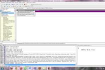
Rice. 15.6. "Control Panel"
In the window that appears, select the "Hardware" tab and click on the "Device Manager" button. The Device Manager window opens. In the window that appears, in the tree-like list, select the line “Ports (COM and LPT). In the drop-down list, you will see all the ports available on your computer. Choose your virtual port: "Converter" USB - COM ". I have a "Prolific" model converter.

Rice. 15.7. List of available ports
Click on this line with the RIGHT mouse button, in the window that opens, select the "Properties" construction.

Rice. 15.8. Configuring the selected port
In the window that appears, select the "Port Settings" tab. In the line "Speed" select "115200", then click on the "Advanced" button.

Rice. 15.9. Configuring Port Parameters
At the bottom of the window that opens, find the "COM port number" tab.

Rice. 16. Changing the COM port number
Click on the tab and select the desired COM port number.
Note that some of the port numbers may be occupied by existing hardware, such as an internal modem. You cannot use one port at a time!
After completing the settings, click "OK" to save the changes and completely exit the settings mode by closing everything earlier open windows... Then restart your computer to make the necessary changes. If you changed the "COM" number of the "USB - COM" port of the converter, then you just need to remove it from the computer connector and reconnect it.
Ready-made solutions for USB-COM adapters from manufacturers.
Adapter cable COM 9 / 25M -> USB AM 1m
Price - RUB 300
Description A cable for connecting devices with a serial interface (RS-232) to the USB port.
Cable or adapter connectors COM25M, COM9M, USB A
Compatibility
USB 1.1 / 2.0 compliant
Supports Windows 2000, Windows XP
Other
Cable length 1 meter
Logistics
Package dimensions (measured in NIKS) 21.5 x 14.5 x 4.1 cm
Gross weight (measured in NIKS) 0.136 kg
TRENDnet Adapter Cable 
Price - RUB 500
The main
Brand TRENDnet
Model TU-S9
Equipment type Adapter cable
Diameter 28/24 AWG
Performance parameters
Data transfer rate 500 Kbps
Powered by USB port
Power Consumption 500mA - Maximum
Compatibility
System Requirements RAM 64 MB
Supports Windows ME, Windows 2000, Windows XP
Other
RoHS Compliance
Cable length 0.6 meters
Weight 75 grams
Working temperature 0 ~ 40 ° C
Package dimensions (measured in NICS) 23 x 16.8 x 4.6 cm
Gross weight (measured in NIKS) 0.135 kg
External sources information
Link to the manufacturer's website www.trendnet.com
Adapter - USB-COM (RS-232) adapter
Price - RUB 1,500
The adapter is intended for the use of devices and adapters designed to be connected through the Com (RS232) port, for example, this is very important when using modern computers that have only USB, in this case, with this adapter you can use modern computers and laptops together with our devices and adapters such as BMW Scanner, Mercedes Scanner, Scanmatik, etc.
Car service equipment, car diagnostics, diagnostic equipment, car diagnostics, car scanner, autoscanner, diagnostic post, chip tuning, car diagnostic equipment Carbrain, UNISCAN, ADP-504, KKL-USB, KKL-COM, BMW scanner, Opel scanner, BMW 1.3 .6, Automan, Opel scanner, BMW scanner, motor tester, gas analyzer, engine diagnostics, instrument panel diagnostics Transponder programmer, OBD-2, OBD2, odometer correction, U-581, engine start, crash data, crash date, crash date, speedometer, tachometer.
Although you may need to use a null modem cable (2-3, 3-2, 5-5) and an adapter of the type -

Add to the adapter USB extension cable here's a straight null modem cable.

- Retail value 100 rub.
- Type A-A
- Length: 1.5m
But for the rest you need " inverted" null modem cable.

- Retail price RUB 155.00
- Connector type: DB9 F - DB9 F
- Length: 1.8 m
or an adapter like this:
STLab U-350 (RTL) COM adapter 9M -> USB AM
Price - RUB 350
The main
Manufacturer St-Lab
USB Model DONGLE SERIAL 1 PORT
Description The adapter allows you to connect a device with an RS-232 interface (for example, a modem) to a USB port on your computer.
Equipment type Adapter cable
Connectors for cable or adapter COM9M, USB A
Built-in USB connector Yes
Performance parameters
Baud rate 115200 bps
USB 1.1 interface
Powered by USB port
Supports Windows 2000, Windows ME, Windows XP, Windows Vista, Windows 2003 Server
Package dimensions (measured in NICS) 17 x 13 x 3.2 cm
Gross weight (measured in NIKS) 0.077 kg
External sources of information Link to the manufacturer's website
This article provides a selection of circuits that allow you to assemble a simple but extremely useful device: Com adapter.
Serial port (RS-232), or as it is also called COM-port, is designed to exchange information between a computer and peripheral devices. It was called sequential because the exchange of data on it occurs bit by bit one at a time.
Originally, the COM port was intended to connect the modem to a computer. In the future, they began to connect a mouse, a scanner, and other peripherals to it. It is also possible to organize a direct connection of two computers using a COM port.
Today, the vast majority of computers are not equipped with an RS-232 connector, since the USB standard has become widespread. But there are still many external devices working only with a COM port (various programmers, diagnostic equipment, receivers, etc.). The way out of this situation is to use a COM-USB adapter device. Below are several options for the most popular circuits of this adapter.
Complete adapter - COM adapter for USB port
on the FT8U232BM chip
The basis of this circuit is the FT8U232BM microcircuit - manufactured by FIDI Ltd. The device built according to this scheme supports all signal levels (DCD, RX, TX, DTR, GND, DSR, RTS, CTS, RI) according to the COM port pinout.

Operating voltage: 3.3 ... 5.5 V, interface: TX RX VCC GND ...

 To match the TTL levels of the RS232 interface with the levels of the FT8U232BM microcircuit, two 74HC00 microcircuits are used. The 93C46 memory chip is designed to store the personal number (PID), manufacturer's code (VID), as well as the serial number of the device. This microcircuit does not need to be installed. In this case, it will be possible to connect only 1 device creating a virtual COM port to the computer. The memory chip AT93C46 can be replaced with AT93C66, AT93C56. 93С46 is flashed directly on the board using the manufacturer's proprietary utility FTDI.
Simplified version on FT8U232BM
This is a diagram of a simplified USB-COM adapter that only supports signal lines RX, TX, RTS, CTS RS232 interface. To match the com port levels with digital levels FT8U232BM added to the circuit.

Adapter circuit for COM from USB to PL2303
The following circuit is based on the PL2303HX chip, which is a USB to RS232 converter. PL2303HX is manufactured by Taiwan Prolific. This circuit also uses a MAX232 transceiver that converts the RX, TX signals.

To work properly, you need to install the driver for the virtual COM port. To do this, download and install the driver from the link below.
Then we configure the virtual port: we set it in the "flow control" window - NO. Then we select a free port number.

USB - COM adapter on the Attiny2313 microcontroller
 Power is supplied directly from the USB power bus. The entire circuit is assembled on a single-sided board (SMD and TN options). The device only supports Rx and Tx signals.

The firmware for the adapter, the drawing of the printed circuit board (SMD and TH), as well as the terminal program for testing the adapter can be downloaded from the link below:
When, fuses must be set as follows:

For the device to work, you need to install the virtual COM port driver. To do this, download it:
Now we insert our adapter into the USB port of the computer, the computer should display the message "Found a new device", and then will offer to install a driver for it. Select the item "Install from a specified location" and click on the button "Next". Then, in a new window, select the path to the folder of the downloaded and unpacked driver and press the "Next" button again. After a few seconds, the driver will be installed and the device will be ready for use.
To check the operability of the device, temporarily close the Rx and Tx outputs and from the terminal program, which is also in the archive, set the COM port number and send any message. To do this, write for example "Hello" and press the "Send" button. If the adapter is working, then the written message will appear in the upper window of the program.
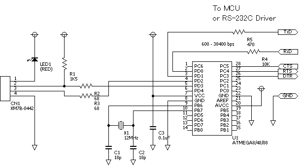
COM-USB adapter for Atmega8 microcontroller
Another COM-USB adapter circuit is now on the Atmega8 microcontroller (Atmega48, Atmega88). The circuit provides processing of Rx, Tx, DTR, RTS, CTS signals of the RS232 interface. The virtual port driver for this circuit is the same as for the attiny2313 adapter.

Firmware for atmega8 / 48/88 and PCB drawing can be downloaded from the following link:
Programming fuses for atmega8 / 48/88:

Recently (more precisely, for many years) computers, both laptops and desktops, are not equipped with RS-232 serial ports. The need for this interface has simply disappeared - there are practically no mass external devices left on the market that are connected via a standard COM port. But, nevertheless, there are many applications and devices that use only serial ports of the RS-232/422/485 standards. These are various receivers in which flashing is performed through a serial port, diagnostic equipment for cars, and much more. If there is no such port in the computer, then what to do?
You can buy specialized USB to RS-232 serial adapters at almost any computer store. The price range of such adapters is simply huge: from $ 1 for a "lace" of dubious origin on eBay, to $ 30-50-100 for devices, some of which are no different in appearance from a one-dollar "lace". So what should you choose? The Internet is full of both positive and negative reviews about very inexpensive adapters. For someone they work without problems, for someone the same model refuses to work to death. Why? There are two possible problems: It can be either a software problem or a purely hardware problem.
First, I’ll say a banality that you should not expect miracles from inexpensive devices... High quality software is not something that a small company can afford. And components for production are also very different in price.
Why can't my USB-COM adapter see my device?
There are several possible reasons.
1. What does such an adapter consist of? Ideally, a USB to serial bridge and a level converter to RS-232. The fact is that the output bridge has TTL levels, that is, from 0 to (specifically for these bridges) a maximum of 3.3 V. Often the voltage does not even reach 3 V. According to the RS-232 standard, the signal should be from ± 5 V to ± 15 V, moreover, the receiver must receive a signal with a spread of ± 3 V. Here we see the reason for the first savings - often the manufacturer simply does not use a level converter, since, theoretically, + 5V ± 3V gives as much + 2V, and at the output, as a rule, from +2.5 to 3.3V, but getting a logical 1 with a voltage from even from -2 to -15V is impossible. Those. even in principle, such an adapter cannot work with RS-232, only with controllers that also have TTL levels at the input. However, there are also such devices, albeit infrequently. There is one more problem: some RS-232 microcircuits enable the power saving mode (sleep mode). If the inputs are less than ± 3V, it will not even come out of hibernation, i.e. in the case without a level converter, never at an output voltage of 2.5 V. In "correct" adapters, the typical voltage at the outputs is ± 6.5V, which is well within the standard.
Figure 1. "Correctly" made USB-COM Mini adapter cable:
The wires are not soldered directly into the board, but are connected with a connector. This prevents mechanical breakage of the wires.
There is an indication - 2 LED.
The board itself is varnished, all holes are gold plated against oxidation.
Two microcircuits: both a bridge (in this case, FTDI FT232RL) and a level converter ZT231LEEA.
High-quality installation, high-quality element base.
If you have to use the adapter often, carry it constantly in your bag, connect in rooms with dusty or aggressive environment, then all these "little things", which most manufacturers usually save on, will not seem like little things to you. In addition, all 9 RS-232 signals are wired, which allows this adapter to be used with any RS-232 devices.
2. Another quality criterion is the adapter's support for all 9 standard RS-232 signals. In many models of inexpensive adapters, only 3 signals out of 9 are supported. For many devices, this is quite enough, for example, to control a frequency converter. Other devices, such as barcode readers, need all 9 signals. Again, the adapter, which has a full set of modem signals, can easily work with any RS-232 devices, and those with only 3, alas ... But manufacturers do not always advertise this property of their products. So when looking for an adapter, check what signals are needed to connect your device, and check that they are supported by the adapter you have chosen. By the way, not all USB-UART bridges support all modem signals.

Many people who have their hands screwed on properly want to make these adapters themselves. On the Internet you can find diagrams, drawings of printed circuit boards and detailed recommendations... Is it worth the candle? Of course, if for you personally this is a matter of principle, then this is understandable. But looking at the prices of microcircuits, I, for example, would have lost all interest in such work. Only the microcircuit of the TTL to RS-232 level converter MAX213EWI costs 200 rubles retail. At the same time, this microcircuit operates at a maximum speed of only 115 Kbit / s, and not 921 Kbit / s, as in the "correct" models. Have you thought why they are not put into cheap adapters? The cheapest USB-UART bridge PL2303 costs 210 rubles, FT232RQ - 360, FT232RL - 460, TUSB3410 - 530 rubles. Here I would like to note that the FT232RQ, FT232RL microcircuits are one and the same, only with a small, but for some very significant difference - the MTBF of the first microcircuit is 2.5 times less than that of the second. Although this time is not at all short. This is without attachments, boards, connectors and housing. So, before taking on such a job, it makes sense to think, maybe a ready-made one is also a good option? However, everyone knows that some manufacturers (the Chinese, although it is not politically correct to point a finger at them) can make, to put it mildly, a low-quality product from FTDI and Texas Instruments, so take a closer look at the manufacturer and its reputation.
And yet, if you decide to make such an adapter with your own hands, you can find in the datasheets of chip manufacturers detailed diagrams such devices for every taste. Once again I will repeat the links to the most popular microcircuits:
Problems with the "firmware" of receivers. Lack of COM port. Laptop use
Most "old" computers and laptops purchased more than 5 years ago always had several COM ports (RS-232). At least there has always been at least one RS-232 connector.
Rice. 1. Connector on the computer case
Various external equipment was connected to it: mice, printers, modems, specialized equipment. Therefore, there were no problems with connecting the receiver to the computer for "firmware". It was enough just to connect, run the program to update the receiver's software and calmly do everything necessary.
In modern computers, the RS-232 connector is often absent. This is where problems arise, often very unpleasant. In most receivers, there is no other way of "flashing" other than using "RS-232". And not all receivers have a "USB" input for connecting an external flash drive.
And sometimes there is another problem: the laptop has a "COM" port, but it works with receivers of one model, but not with others. This is due to the violation by the laptop manufacturer of the "RS-232" data transmission standard. They go to this in order to save the energy of the battery charge. If the manufacturer of the receiver was technically scrupulous and accurate, then a special microcircuit for the "COM" port will be installed in the receiver. Thanks to this microcircuit, the receiver will work with both a laptop and a computer. But the installation of the microcircuit increases the total cost of the product, and lately manufacturers are saving even on these trifles! Therefore, there is a problem of incompatibility between laptops and most receivers.
When using a computer, the problem of lack of the necessary "RS-232" ports is solved simply: you need to purchase an additional module with "COM" ports. This board installed in the computer is called "PIC-COM" or simply "COM port board".
Rice. 2. PCI card for a computer with two "COM" ports
If you are not good at computers and have never dealt with the installation of additional equipment in a computer before, then contact a specialist! Otherwise, you can "kill" expensive equipment.
After installing the card into the computer, the operating system "Windows" - "OS" assigns a number to the newly installed ports, for example, "1", "2" ... "25".
When using a laptop, you cannot install a regular board from a computer: it is not the same standard and size. There are two ways to solve this problem: expensive, but high quality, and cheap, but not fully compatible. In the first case, you need to purchase a special board with ports for the laptop. The price of these boards is high, and I could not buy this board, even on order.
Rice. 3. Board for laptop with "COM" port
And here's the catch: "old" and "new" laptops have two different standards for additional equipment! Before purchasing, check the instructions for your laptop!
If you could not purchase a board for a computer or laptop, then there is only one way out: "USB". Almost all modern computer models have a "USB" output, at least two, or even all eight! Various USB to COM converters are available on the market.
Rice. 4. Converter "USB - COM"
Rice. 5. Scheme of the converter "USB - COM"
How to solder the USB-COM adapter yourself. Option 1
How to make a USB-COM adapter yourself, which can be used to connect converters and other devices to computers that do not have an "iron" COM port.
Attention!
The adapter described below will only match the RX and TX signals.
All other modem signals are inactive.
For most devices without hardware flow control, this is more than enough.
With Pilot VAF / MAF converters, the adapter works 100%
Go!
To assemble you need the following parts:
1. PL2303HX (USB-USART bridge from Prolific) -1pc.
2.MAX232CSE (UART-RS232) -1pc.
3. Quartz 12.00 MHz-1 pc.
4. Capacitors 10 nF (smd1206) -2 pcs.
5. Capacitors 1 uF (smd1206) -6 pcs.
6. Resistors 27 Ohm (smd1206) -2 pcs.
7. Resistors 1.5KΩ (smd1206) -1pc.
8. Connector mini-USB -1 pc.
9. DB-9 male connector - 1 pc.
10. Foil PCB for board 48 * 22mm - 1pc
Adapter circuit
Printed circuit board
Schematic files and seals in the format Eagle PCB Editor can be downloaded from this link
Build and setup
Here, in fact, everything is elementary - we make a board, drill 4 holes and solder all the details.
As a result, you should get such an adapter:
To prevent oxidation, the board can be blown out with polyurethane varnish or any quick-drying automotive varnish that is at hand.
Next, we connect this device to the USB port of the computer.
Windows will detect a new device and ask for a driver
We go to the site of prolific and download the latest version of firewood
At the time of this writing, the latest driver was this one.
After feeding the driver to Windows, a new Prolific COM port should appear in the system:
Now you need to check the functionality of the adapter
To do this, on the adapter in the COM port connector, use a screwdriver or wire to close pins 2 and 3 together (on the connector itself, numbers with contact numbers are usually knocked out - take a closer look) Alternatively, you can solder a temporary jumper:
Next, run the program "Hyperterminal" (Start-> Programs-> Accessories-> Communication-> Hyperterminal)
There is no hyperterminal on whist and seven! Therefore, you will have to go to Google / Yandex to download the hyperterminal or any of its analogs.
We select our new som port in the connection settings:
Now we launch the connection, select the English layout and try to print something.
The symbols of the keys pressed should appear on the screen:
If the letters do not appear, then check the installation
That's all!
Now it remains to remove the jumper from contacts 2-3 and you can use the adapter for its intended purpose.
Those. the input of such a “converter” is connected to a free “USB” connector of the laptop, the driver (control program) is installed from the disk from the kit, and a virtual COM port with the assigned serial number appears in the system settings.
How to solder the USB-COM adapter yourself. Option - 2
| Picture 1.General form |
|
The proposed block in assembled form allows to implement the principle: buy - connect. The device will allow users of personal computers to connect devices operating from the COM port (RS232C) to the USB port.
Estimated retail price: 540 rubles
The adapter will be useful in practical applications: for connecting various devices to a personal computer, as well as modems and programmers.
Specifications
Supply voltage from USB port: 5 V.
Consumption current: 20 mA.
RS232C communication speed: 110-230000 bps
Interface: USB1.1, USB2.0.
Supported operating systems: Win98, Win2000, WinXP, Vista, Linux, etc.
Overall dimensions of the device: 60x30 mm.
Contents of delivery
Adapter block assembly: 1.
Instructions: 1.
Design
Structurally, the adapter is made on a double-sided printed circuit board made of foil-clad fiberglass, protected by a transparent heat-shrinkable tube.
The adapter provides all modem signals: DSR, DTR, RTS, CTS, RI, DCD, as well as the main signals RXD and TXD.
Figure 2. Electrical schematic diagram
Figure 3. View of the printed circuit board from the side of parts
Block operation description
The schematic diagram is shown on pic 2.
The central part of the device is a CP2102 microcontroller manufactured by SILICON LABORATORIES. A MAX3243 converter manufactured by Texas Instruments is used as a level driver microcircuit. The adapter provides all modem signals: DSR, DTR, RTS, CTS, RI, DCD, as well as the main signals RXD and TXD.
Installing the device in the OSTo install drivers for your computer, you must first download the driver appropriate for your operating system.
Next, install the driver on your personal computer. Connect the adapter. The operating system will detect it and "ask" for the driver, you should tell it the location of this driver (the place where it was unpacked).
After successful installation, the LED on the adapter should light up, signaling the readiness of the device for operation!
NEW Updated driver from 01/25/2011
1. Driver for Win Vista you can download
2. Driver for Windows 2000 / XP / Server 2003 / Vista (v5.0) You can download
3. Driver for Linux you can download
4. Driver for Win98SE you can download
5. Driver for OC Mac you can download
6. an144sw.zip- using this program, you can change the ID codes of the USB-COM adapter. This is necessary in order to be able to use several 8050s on one PC. Use for advanced users only! You can download
PERFORMANCE CHECK BM8050 WITHOUT EXTERNAL EQUIPMENT
To check the transmission and reception of all necessary modem signals according to the connection of the COM device.
Place jumpers on pins 2-3, 4-6, 7-8 of the BM8050 COM-connector.
Connect the device to the USB port of the PC.
See which port the OS has allocated for the device, for which go to Start --- Settings --- Control Panel --- System --- Hardware --- Device Manager --- Ports (COM and LPT) --- Silicon Labs CP210x USB to UART Bridge (COM1).
Launch the standard HiperTerminal application for Windows from Start --- Programs --- Accessories --- Communication --- HiperTerminal.
Stop the running connection, if it is active, for which click the Call --- Stop above.
See which port is used by the program to communicate with the device, for which go to the top left File --- Properties and opposite "Connect via" select the same port as in the Device Manager (in our case, COM1).
In the same window, make sure that the "Hardware" flow control is selected in the program, for which click the button in the center "Configure" and in the lower "Flow control" window select "Hardware".
Exit the program settings, for which click OK, OK again.
Type the text "Text" in the HiperTerminal software, and the text "Text" is printed on the screen, which confirms that the device is working.
Remove the jumpers from contacts 2-3, 4-6, 7-8 of the BM8050 COM connector.
Type the text "Text" in the HiperTerminal software, and there is no print on the screen, which confirms that the device is working.
Driver setup and port selection for USB-COM adapter
Here the first problems await us: firstly, the OS could assign a too large number to the virtual port, for example, "25". And the program for "flashing" the receiver allows you to work with port numbers from one to four. Secondly, not all USB-COM converters can work with the firmware and the receiver itself. The reason is that equipment manufacturers have made their products and programs for them in different ways. It is necessary to check all converters individually for your program and your receiver. It often happens that the converter works with one piece of equipment, but not with the other.
If the first problem is fixed by changing the port number in the OS settings, then the problem of hardware, program and converter compatibility cannot be fixed.
To change the number assigned to the asset, you must change it manually. To do this, you need to enter the "Device Manager": "Start" - "Settings" - "Control Panel" - "System".
Rice. 15.6. "Control Panel"
In the window that appears, select the "Hardware" tab and click on the "Device Manager" button. The Device Manager window opens. In the window that appears, in the tree-like list, select the line “Ports (COM and LPT). In the drop-down list, you will see all the ports available on your computer. Select your virtual port: "USB to COM converter". I have a "Prolific" model converter.
Rice. 15.7. List of available ports
Click on this line with the RIGHT mouse button, in the window that opens, select the "Properties" construction.
Rice. 15.8. Configuring the selected port
In the window that appears, select the "Port Settings" tab. In the line "Speed" select "115200", then click on the "Advanced" button.
Rice. 15.9. Configuring Port Parameters
At the bottom of the window that opens, find the "COM port number" tab.
Rice. 16. Changing the COM port number
Click on the tab and select the desired COM port number.
Note that some of the port numbers may be occupied by existing hardware, such as an internal modem. You cannot use one port at a time!
After completing the configuration, click "OK" to save the changes and completely exit the settings mode by closing all previously open windows. Then restart your computer to make the necessary changes. If you changed the "COM" number of the "USB - COM" port of the converter, then you just need to remove it from the computer connector and reconnect it.
Ready-made solutions for USB-COM adapters from manufacturers.
Adapter cable COM 9 / 25M -> USB AM 1m
Price - RUB 300
Description A cable for connecting devices with a serial interface (RS-232) to the USB port.
Cable or adapter connectors COM25M, COM9M, USB A
Compatibility
USB 1.1 / 2.0 compliant
Supports Windows 2000, Windows XP
Other
Cable length 1 meter
Logistics
Package dimensions (measured in NIKS) 21.5 x 14.5 x 4.1 cm
Gross weight (measured in NIKS) 0.136 kg
TRENDnet Adapter Cable
Price - RUB 500
The main
Brand TRENDnet
Model TU-S9
Equipment type Adapter cable
Diameter 28/24 AWG
Performance parameters
Data transfer rate 500 Kbps
Powered by USB port
Power Consumption 500mA - Maximum
Compatibility
System Requirements RAM 64 MB
Supports Windows ME, Windows 2000, Windows XP
Other
RoHS Compliance
Cable length 0.6 meters
Weight 75 grams
Working temperature 0 ~ 40 ° C
Package dimensions (measured in NICS) 23 x 16.8 x 4.6 cm
Gross weight (measured in NIKS) 0.135 kg
External sources of information
Link to the manufacturer's website www.trendnet.com
Adapter - USB-COM (RS-232) adapter
Price - RUB 1,500
The adapter is intended for the use of devices and adapters designed to be switched on via the Com (RS232) port, for example, this is very important when using modern computers that have only USB, in this case, using this adapter, you can use modern computers and laptops together with our devices and adapters such as BMW Scanner, Mercedes Scanner, Scanmatik, etc.
Car service equipment, car diagnostics, diagnostic equipment, car diagnostics, car scanner, autoscanner, diagnostic post, chip tuning, car diagnostic equipment Carbrain, UNISCAN, ADP-504, KKL-USB, KKL-COM, BMW scanner, Opel scanner, BMW 1.3 .6, Automan, Opel scanner, BMW scanner, motor tester, gas analyzer, engine diagnostics, instrument panel diagnostics Transponder programmer, OBD-2, OBD2, odometer correction, U-581, engine start, crash data, crash date, crash date, speedometer, tachometer.
Although you may need to use a null modem cable (2-3, 3-2, 5-5) and an adapter of the type -
Add to the adapter USB extension cable here's a straight null modem cable.
- Retail value 100 rub.
- Type A-A
- Length: 1.5m
But for the rest you need " inverted" null modem cable.
- Retail price RUB 155.00
- Connector type: DB9 F - DB9 F
- Length: 1.8 m
or an adapter like this:
STLab U-350 (RTL) Adapter COM 9M -> USB AM
Price - RUB 350
The main
Manufacturer St-Lab
Model USB DONGLE SERIAL 1 PORT
Description The adapter allows you to connect a device with an RS-232 interface (for example, a modem) to a USB port on your computer.
Equipment type Adapter cable
Connectors for cable or adapter COM9M, USB A
Built-in USB connector Yes
Performance parameters
Baud rate 115200 bps
USB 1.1 interface
Powered by USB port
Supports Windows 2000, Windows ME, Windows XP, Windows Vista, Windows 2003 Server
Package dimensions (measured in NICS) 17 x 13 x 3.2 cm
Gross weight (measured in NIKS) 0.077 kg
External sources of information Link to the manufacturer's website
The holidays are finally over and it's time to do something.
Let's start, perhaps, with a necessary device that makes life easier for an ordinary electronics engineer - a device for communicating with a computer. This is necessary in order to transfer data to a computer (temperature from sensors, position of doors, engine speed, table of values from a recorder ...) or to receive data from a computer (tables of values for calculations, setting data for devices, new firmware for the bootloader ...). For debugging a new device (to see what is happening in the brains of the microcontroller) is generally an irreplaceable thing.
As you know, there are many interfaces through which the microcontroller can communicate with the outside world. But when it comes to communication with a computer, the RS-232 interface (COM port) is beyond competition. The reason is the simplicity of working with the port from the computer side and the presence of a large number of programs intended for this. In addition, almost every microcontroller has a hardware-supported USART interface (this is the same RS-232, only with voltages of 0 - 5v), which makes the communication process easy to implement.
In order to bring the signal levels of the microcontroller USART to the levels of the COM port of the computer, you need to assemble a simple converter (for example, on the MAX232), but you can go along a more interesting path
A more interesting way is to build a UART to USB converter. In this case, the USB port is perceived by the computer as a virtual COM port. In this case, we kill several birds with one stone:
- There is a USB port in any computer (although the COM port is still quite common, but on laptops it is no longer there);
- as it turned out, the UART to COM (RS-232) converter is much more difficult to make than the UART to USB (I made a programmer for the COM port with a MAX232 converter twice - both times unsuccessfully);
- if you connect the converter via a USB hub, then we get several virtual COM ports on one USB at once, plus security for the computer, since the hub acts as a buffer.
Here is the UART to USB converter schematic.
This is not my device. Taken this scheme from www.recursion.jp/avrcdc/. The reason why I am presenting it here is the simplicity of the circuit and the cheapness of manufacture. Assembling the circuit is quite simple (you can even use a breadboard).

I made the finished device in the form of a "flash drive" in order to make it more convenient to use in the "field" conditions. For greater comfort, you can take a USB extension cable, attach it to the computer with one connector, insert our "USB flash drive" into the second and get mobile device, which can be easily connected to any circuit.

PCB double-sided, suitable for ATmega8 / 48/88/168 microcontrollers
Here is an option for manufacturing according to the technology described
Firmware for various microcontrollers:
Fuses for CodeVisionAVR, PonyProg are set inversely
The SPI interface for the programmer is brought out along with all the interfaces on the back of the "flash drive" - we connect the programmer right there. We solder the reset pin near the reset leg (so as not to interfere). During programming, the converter must be powered with 5v voltage from the interface side. It is undesirable via USB, as the supply voltage through the LED will decrease. If problems arise due to large noises, we hang a pull-up resistor to the power supply on the reset leg (5-10 kOhm). The presence of the LED is mandatory - it is used as a voltage regulator. The firmware provides for the operation of control lines (CTS, RTS, DTR), but they are not needed for UART and I did not output them to the interface connector. If you need them, you just need to "throw" the jumpers from the microcontroller legs to the interface connector legs.
After the device is assembled,
you need to install the virtual COM port driver.
The archive contains folders for different Win:
/ raw - for (Windows 2000 / XP)
/ w2k - for Windows 2000 (bulk mode only)
/ xpvista7 - for Windows XP / Vista / 7 x32
/ vista64 - for Windows Vista x64
This is done very simply:

1
Insert the "USB flash drive" into the USB port;

2
We receive a message in the tray that a new device has been found;

3
The "Found New Hardware Wizard" will start, select "Install from a Specified Location", click "Next";

4
We select "Include the next place for search" and in the window specify the desired path to the driver;
5
Click "Next", the driver will be installed, click "Finish"
Now in the "Properties" of "my computer" in the "Hardware" tab, click the "Device Manager" button. In the window of the device manager in the "Ports (COM and LPT)" section, we will see a new device - "Virtual Communications Port (COM5)".

Each USB port will be assigned its own virtual COM port (COM5, COM6, COM7, etc.).
Ready! Now you can use the converter.
Let's check the efficiency of the converter, for this we need to short-circuit the input to the output (RxD, TxD) and send messages from the computer via the virtual port. Messages sent should be returned as received.
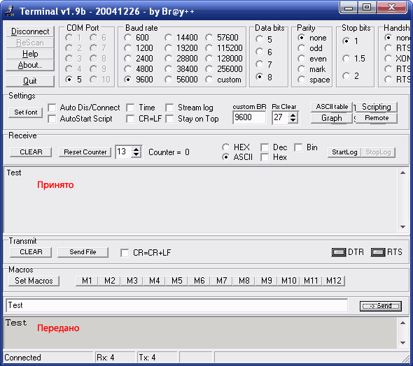
 We attach a "jumper" jumper to the required pins. We launch the program for working with the COM port. You can use the standard Windows hyperterminal, but I prefer another program - small, portable and functional.
Launch the program, set the desired port (look at the port number in the device manager), leave the speed and other parameters as they are, click "Connect", in the window near the "-> Send" button, write a message, click "-> Send" and see the result ... The lower window is the sent message, the large window is the received message. If everything works, the messages will be the same.
This "flash drive - interface converter" will later turn into I2C toUSB, SPI to USB, SPI to UART, etc. you just need to reflash it with the necessary firmware. (Something I am beginning to notice in myself a craving for universalization :)).

P.S. The source site recommends connecting them through a matching circuit to match the voltage levels of the converter (3.3v) and the device (5v). But I think the resistors in the RxD, TxD lines should be enough for matching - you need to try.

P.P.S. This is the first practical scheme in the blog - there will be more of them later, since we seem to have figured out the basics (there are still some questions left - I will write on the sly).
(Visited 31,429 times, 4 visits today)