Sometimes you walk past parked cars, and you notice out of the corner of your eye that someone for a long time, judging by the dim glow of the lamps, forgot to turn off the light. Somebody got into it too. It’s good when there is a regular indicator of the light is not turned off, and when there is no such handicraft will help: Nezabyvayka can squeak when the light is not turned off and can beep the reverse gear.
The circuit of the digital fuel level indicator has a high degree of repeatability, even if the experience with microcontrollers is negligible, so understanding the intricacies of the assembly and tuning process does not cause problems. The Gromov Programmer is the simplest programmer that is needed to program the avr microcontroller. The Goromov programmer is well suited for both in-circuit and standard circuit programming. Below is a diagram of the control of the fuel indicator.
Smooth switching on and off of the LEDs in any mode (the door is open and the ceiling is on). It also auto shuts off after 5 minutes. And the minimum current consumption in standby mode.
Option 1 - Switching by minus. (using N-channel transistors) 1) "negative switching", i.e. such an option in which one supply wire of the lamp is connected to the + 12V battery (power source), and the second wire switches the current through the lamp, thereby turning it on. In this option, a minus will be given. For such circuits, it is necessary to use N-channel field-effect transistors as output switches.
The modem itself is small, inexpensive, works without problems, clearly and quickly, and in general there are no complaints about it. The only negative for me was the need to turn it on and off with a button. If it was not turned off, then the modem worked from the built-in battery, which eventually sat down and the modem had to be turned on again.
The principle of operation is simple: turning the knob adjusts the volume, pressing it turns the sound off and on. Needed for car writing on Windows or Android
Initially, in Lifan Smily (and not only), the rear wiper mode is the only one, and it is called “always wave”. This mode is especially negatively perceived in the onset of the rainy season, when drops collect on the rear window, but in an insufficient amount for one pass of the janitor. So, you have to either listen to the creak of rubber on glass, or portray a robot and periodically turn the janitor on and off.
I slightly modified the circuit of the time delay relay for switching on the interior lighting for a Ford car (the circuit was developed for a very specific car, as a replacement for the standard Ford 85GG-13C718-AA relay, but was successfully installed in the domestic "classic").
This is not the first time such crafts have been thrown around. But for some reason people snuggle up on the firmware. Although most of them are based on elmchan's "Simple SD Audio Player with an 8-pin IC" project. The source is not opened, arguing that I had to fix the project, that my quality is better ... etc. In short, they took an open source project, assembled it, and passed it off as your own.
So. Attiny 13 microcontroller - heart so to speak this device. I suffered with his firmware for a long time, I could not flash it in any way. Neither 5 wires through LPT, nor Gromov's programmer. The computer simply does not see the controller and that's it.
In connection with innovations in traffic rules, people began to think about the implementation of daytime running lights. One of the possible ways is to turn on the high beam lamps for part of the power, this is what this article is about.
This device will allow the dipped beam to automatically turn on when you start driving and adjust the voltage on the low beam lamps, depending on the speed at which you eat. Also, it will serve as a safer movement and extend the life of the lamps.

The principle of closing the cell door is very simple. The cage door is supported by a special stop made of copper wire. A nylon thread of the required length is attached to the stop. If you pull the thread, the stop slides off, and the cage door closes under its own weight. But it's in manual mode, and I wanted to implement an automatic process without anyone's participation.
A servo drive was used to control the closing mechanism of the cage door. But in the process of work, he created noise. The noise might startle the bird. Therefore, I replaced the servo drive with a commutator motor taken from a radio-controlled car. It worked quietly and was ideally suited, especially since the commutator motor was easy to operate.

To determine if a bird is already in a cage, I used an inexpensive motion sensor. The motion sensor itself is already a finished device, and nothing needs to be soldered. But this sensor the response angle is very large, and I need it to react only in the inner region of the cage. To limit the response angle, I placed the sensor in the base, which once served as an economy lamp. I cut out a kind of plug from cardboard with a hole in the middle for the sensor. Having played around with the distance of this plug relative to the sensor, I set the optimal angle for the sensor to operate.

As a barker for birds, I decided to use the WTV020M01 sound module with the singing of a siskin and a goldfinch recorded on a microSD memory card. Those were the ones I was going to catch. Since I used one sound file, then I decided to control the sound module in a simple way, without using the exchange protocol between the sound module and the microcontroller.
When a low signal was applied to the ninth leg of the sound module, the module began to play. As soon as the sound was reproduced on the fifteenth leg of the sound module, the low level. Thanks to this, the microcontroller monitored the sound reproduction.
Since I implemented a pause between sound playback cycles, to stop sound playback, the program sends a low level to the first leg of the sound module (reset). The sound module is a complete device with its own sound amplifier, and, by and large, it does not need an additional sound amplifier. But this sound amplification seemed not enough to me, and I used the TDA2822M chip as a sound amplifier. In audio playback mode, it consumes 120 milliamps. Considering that the capture of a bird will take some time, as autonomous battery I used a not quite new battery from an uninterruptible power supply (it was still lying around idle).
The principle of an electronic birder is simple, and the circuit consists mainly of ready-made modules.
Program and scheme -
Now I have two identical programmers on my desk. All to try new firmware. These twins will sew each other. All experiments are carried out under MS Windows XP SP3.
The goal is to increase the speed of work and expand the compatibility of the programmer.

The popular Arduino IDE development environment attracts with a large number of ready-made libraries and interesting projects that can be found on the Web.

Some time ago, I had several ATMEL ATMega163 and ATMega163L microcontrollers at my disposal. Microcircuits were taken from end-of-life devices. This controller is very similar to ATMega16, and in fact is its early version.
Hello Datagor readers! I managed to assemble a voltmeter of minimal dimensions with a segment-by-segment scan of the indicator with a fairly high functionality, with automatic detection of the type of indicator and selection of modes.

After reading Edward Ned's articles, I built a DIP version and tested it in production. Indeed, the voltmeter worked, the current through the output of the microcircuit to the indicator did not exceed 16 milliamps per pulse, so the operation of the microcircuit without resistors that limit the currents of the segments is quite acceptable and does not cause overloads of the elements.
Didn't like it too much frequent update indications on the display and the proposed scale "999". I wanted to correct the program, but the author does not post the source codes.
At the same time, I needed a voltmeter and an ammeter for a small power supply. It was possible to assemble a combined version, or it was possible to assemble two miniature voltmeters, and the dimensions of the two voltmeters were smaller than the combined version.
I stopped my choice on a microcircuit and wrote the source code for the segment-by-segment sweep of the indicator.
In the process of writing the code, the idea of programmable switching of scales and the position of the comma arose, which we managed to implement.
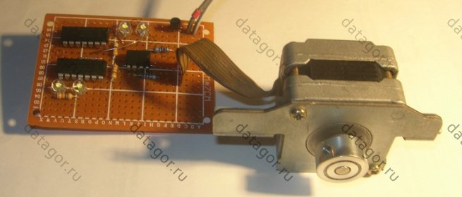
The mechanical encoder is convenient to use, but it has some annoying drawbacks. In particular, contacts wear out over time and become unusable, bounce appears. Optical encoders are much more reliable, but they are more expensive, many of them are afraid of dust, and they are rarely found in a form in which they would be convenient for use in radio engineering.
In short, when I found out that a stepper motor can be used as an encoder, I really liked this idea.
Almost eternal encoder! It is impossible to torture him: you collect once and you can encode all your life.
Digitally controlled pre-amplifier. We use with programming through the Arduino shell, electronic potentiometers from Microchip, graphic TFT.

It was not part of my plans to develop and assemble this device. Well, there's just no way! I already have two preamplifier. Both suit me just fine.
But, as it usually happens with me, a combination of circumstances or a chain of certain events, and now a task has been drawn for the near future.
Hello dear readers! I want to introduce you to "" - a project of a table tennis feeding robot, which will be useful for beginners and amateurs when practicing the technique various types innings to any zone of the table will help to calculate the timing and power of receiving the ball.

Or you can just get used to a new rubber or racquet and give it a good tap.
Greetings readers! I have an elderly computer that is already ten years old. Its parameters are appropriate: a “stump” of 3.0 GHz, a couple of GB of RAM and an ancient motherboard EliteGroup 915 series.

And I decided to attach the old man somewhere (to give, sell), because it's a pity to throw it away. But one trouble interfered with what was planned: the motherboard did not turn on from the power button, and no matter what I did, starting from checking the wires and ending with the continuity of the transistors on the board, I could not find the problem. Give it to specialists for repair - repairs will be more expensive than the entire computer.
I thought and thought and found a way to start my poor fellow. I pulled out the BIOS battery, from which the computer was frightened and immediately started at the next power up! And then - in almost every BIOS there is a PC startup from any keyboard button or the POWER button on the keyboard. It would seem that the problem is solved. But no, there are nuances. Starting from USB keyboards did not work. Plus, I didn’t want to scare the new owner, the computer should start from the usual power button on the case.
I present the second version of the two-channel cyclic timer. New features have been added and changed circuit diagram. The cyclic timer allows you to turn on and off the load, as well as pause for specified time intervals in a cyclic mode. Each of the timer outputs has 2 operating modes - "Logic" and "PWM". If the logical mode is selected, the device allows you to control lighting, heating, ventilation and other electrical appliances using relay contacts. The load can be any electrical devices whose load power does not exceed the maximum current of the relay. The "PWM" output type allows, for example, to connect a DC motor through a power transistor, while it is possible to set the PWM duty cycle so that the motor rotates at a certain speed.
The clock assembled on the ATtiny2313 microcontroller and the LED matrix shows the time in 6 different modes.
The 8*8 LED matrix is controlled by the multiplexing method. The current limiting resistors are omitted from the circuit so as not to spoil the design, and since the individual LEDs are not constantly driven, they will not be damaged.
Only one button is used for control, long press the button(press and hold) to rotate the menu and normal button press to select the menu.
This is a hobby project, because the accuracy of the clock depends only on the calibration of the controller's internal oscillator. I didn't use quartz in this project as it would take up the two pins I needed on the ATtiny2313. Quartz can be used to improve accuracy in an alternative design (PCB).
Frequency counter up to 500 MHz on Attiny48 and MB501
This time I will present a simple small-sized frequency counter with a measurement range from 1 to 500 MHz and a resolution of 100 Hz.
Nowadays, regardless of the manufacturer, almost all microcontrollers have so-called counter inputs, which are specifically designed to count external pulses. Using this input, it is relatively easy to design a frequency counter.
However, this counter input also has two properties that prevent the frequency counter from being used directly for more demanding needs. One of them is that in practice, in most cases, we measure a signal with an amplitude of several hundred mV, which cannot move the counter of the microcontroller. Depending on the type, a signal of at least 1-2 V is required for the input to work properly. Another is that the maximum measurable frequency at the input of the microcontroller is only a few MHz, this depends on the architecture of the counter, as well as on the processor clock frequency.
Thermostat for electric kettle on ATmega8(Thermopot)
This device allows you to control the temperature of the water in the kettle, has the function of maintaining the temperature of the water at certain level, as well as the inclusion of forced boiling of water.
The device is based on the ATmega8 microcontroller, which is clocked from a quartz resonator with a frequency of 8 MHz. Temperature sensor - analog LM35. Seven-segment indicator with a common anode.
Christmas star on Attiny44 and WS2812
This decorative star consists of 50 special RGB LEDs that are controlled by ATtiny44A. All LEDs continuously change color and brightness randomly. There are also several types of effects that are also activated randomly. Three potentiometers can change the intensity of the primary colors. The position of the potentiometer is indicated by LEDs when the button is pressed, and the color change and effect speed can be switched in three steps. This project was built entirely on SMD components due to the special shape of the PCB. In spite of a simple circuit, the board structure is quite complex and hardly suitable for beginners.
Frequency converter for asynchronous motor on AVR
This article describes a universal three-phase frequency converter on a microcontroller (MK) ATmega 88/168/328P. The ATmega takes full control of the controls, LCD display and three-phase generation. The project was supposed to run on off-the-shelf boards such as the Arduino 2009 or the Uno, but this never came to fruition. Unlike other solutions, the sinusoid is not calculated here, but is derived from the table. This saves resources, memory space and allows the MCU to handle and keep track of all controls. Floating point calculations are not performed in the program.
The frequency and amplitude of the output signals are adjusted using 3 buttons and can be stored in the EEPROM memory of the MK. Similarly, it provides external control via 2 analog inputs. The direction of rotation of the motor is determined by a jumper or a switch.
Adjustable V/f characteristic allows to adapt to many motors and other consumers. An integrated PID controller for analog inputs has also been enabled, PID controller parameters can be stored in EEPROM. The pause time between switching keys (Dead-Time) can be changed and saved.
Frequency meter III from DANYK
This frequency meter with AVR microcontroller allows you to measure the frequency from 0.45 Hz to 10 MHz and the period from 0.1 to 2.2 µs in 7 automatically selected ranges. The data is displayed on a seven-digit LED display. The project is based on the Atmel AVR ATmega88/88A/88P/88PA microcontroller, you can find the download program below. The setting of the configuration bits is given on figure 2.
The principle of measurement differs from the previous two frequency counters. The simple method of counting pulses after 1 second, used in the two previous frequency counters (frequency counter I, frequency counter II), does not allow measuring fractions of Hertz. That's why I chose a different measurement principle for my new III counter. This method is much more complicated, but allows frequency measurement with a resolution of up to 0.000001 Hz.
Frequency meter II from DANYK
This is a very simple frequency counter on an AVR microcontroller. It allows you to measure frequencies up to 10 MHz in 2 automatically selected ranges. It is based on the previous design of the frequency counter I, but has 6 digits of the indicator instead of 4. The lower measuring range has a resolution of 1 Hz and works up to 1 MHz. The higher range has a resolution of 10 Hz and works up to 10 MHz. A 6-digit LED display is used to display the measured frequency. The device is built on the basis of a microcontroller Atmel AVR ATtiny2313A or ATTiny2313. You can find the configuration bit setting below.
The microcontroller is clocked from a quartz resonator with a frequency of 20 MHz (the maximum allowable clock frequency). The measurement accuracy is determined by the accuracy of this crystal, as well as capacitors C1 and C2. The minimum half-cycle length of the measured signal must be greater than the frequency period of the crystal oscillator (restriction of the AVR architecture). Thus, at 50% duty cycle, frequencies up to 10 MHz can be measured.
Crafts with microcontrollers is a question more relevant and interesting than ever. After all, we live in the 21st century, the era of new technologies, robots and machines. Today, every second person, starting from a young age, knows how to use the Internet and various kinds of gadgets, without which it is sometimes difficult to manage in everyday life.
Therefore, in this article we will address, in particular, the issues of using microcontrollers, as well as their direct application in order to facilitate the missions that everyday arise before all of us. Let's see what the value of this device is, and how easy it is to use in practice.
A microcontroller is a chip whose purpose is to control electrical appliances. The classic controller combines in one chip, both the operation of the processor and remote devices, and includes a random access memory. In general, this is a single-chip personal computer that can perform relatively ordinary tasks.
The difference between a microprocessor and a microcontroller lies in the presence of start-up devices, timers and other remote structures built into the processor chip. The use in the current controller of a fairly strong computing apparatus with extensive capabilities, built on a monocircuit, instead of a single set, significantly reduces the scale, consumption and price of devices created on its basis.
It follows from this that such a device can be used in computing technology, such as a calculator, motherboard, CD controllers. They are also used in household appliances - these are microwaves, and washing machines, and many others. Microcontrollers are also widely used in industrial mechanics, ranging from microrelays to machine tool control methods.
AVR microcontrollers
Let's get acquainted with the more common and thoroughly established in modern world technology with a controller such as the AVR. It includes a high-speed RISC microprocessor, 2 types of energy-consuming memory (Flash project cache and EEPROM information cache), RAM-type performance cache, I/O ports, and a variety of remote interface structures.

- operating temperature ranges from -55 to +125 degrees Celsius;
- storage temperature ranges from -60 to +150 degrees;
- maximum voltage at the RESET pin, according to GND: 13 V maximum;
- maximum supply voltage: 6.0 V;
- the largest electric current of the input / output line: 40 mA;
- maximum current through the power line VCC and GND: 200 mA.
Features of the AVR microcontroller
Absolutely all microcontrollers of the Mega kind, without exception, have the property of independent coding, the ability to change the components of their driver memory without outside help. This distinguishing feature makes it possible to form very plastic concepts with their help, and their method of activity is changed personally by the microcontroller in connection with a particular picture, due to events from the outside or from the inside.
The promised number of cache rotations for second-generation AVR microcontrollers is 11 thousand revolutions, when the standard number of revolutions is 100 thousand.
The configuration of the structural features of the input and output ports of the AVR is as follows: the purpose of the physiological output has three control bits, and not two, as in well-known bit controllers (Intel, Microchip, Motorola, etc.). This feature eliminates the need to have duplicate port components in memory for protection purposes, and also speeds up the energy efficiency of the microcontroller in combination with outdoor devices, namely, with concomitant electrical problems outside.

All AVR microcontrollers are characterized by a multi-tiered suppression technique. It seems to interrupt the standard course of the Russifier in order to achieve a goal that is in priority and is conditioned by certain events. There is a subroutine for converting a request to pause for a specific case, and it is located in the project memory.
When a problem occurs that triggers a stop, the microcontroller stores the compound adjustment counter, stops the general processor from executing this program, and proceeds to execute the stop processing subroutine. At the end of the execution, under the patronage of the suspension program, the pre-stored program counter is resumed, and the processor continues to execute the unfinished project.
Crafts based on the AVR microcontroller
DIY crafts on AVR microcontrollers are becoming more popular due to their simplicity and low energy costs. What they are and how, using your own hands and mind, to make them, see below.
"Director"
Such a device was designed as a small assistant as an assistant to those who prefer to walk in the forest, as well as to naturalists. Despite the fact that most telephones have a navigator, they need an Internet connection to work, and in places far from the city, this is a problem, and the problem of recharging in the forest has not been solved either. In this case, it would be quite advisable to have such a device with you. The essence of the device is that it determines which way to go and the distance to the desired location.
The circuit is built on the basis of an AVR microcontroller with clocking from an external quartz resonator at 11.0598 MHz. NEO-6M from U-blox is responsible for working with GPS. This is, although outdated, but a well-known and budget module with a fairly clear ability to locate. Information is focused on the screen from Nokia 5670. The model also has a magnetic wave meter HMC5883L and an ADXL335 accelerometer.

Wireless notification system with motion sensor
A useful device that includes a movement device and the ability to give, according to the radio channel, a sign of its operation. The design is movable and is charged with a battery or batteries. To make it, you need to have several HC-12 radio modules, as well as an hc-SR501 motion sensor.
The HC-SR501 displacement device operates on a supply voltage of 4.5 to 20 volts. And for optimal operation from a LI-Ion battery, you should go around the safety LED at the power input and close the access and output of the 7133 linear stabilizer (2nd and 3rd legs). At the end of these procedures, the device starts permanent job at a voltage of 3 to 6 volts.

Attention: when working in combination with the HC-12 radio module, the sensor sometimes falsely worked. To avoid this, it is necessary to reduce the transmitter power by 2 times (command AT+P4). The sensor runs on oil, and one charged battery with a capacity of 700 mAh will last more than a year.
Miniterminal
The device proved to be a wonderful assistant. A board with an AVR microcontroller is needed as a foundation for the manufacture of the device. Due to the fact that the screen is connected directly to the controller, the power supply should be no more than 3.3 volts, since higher numbers may cause problems in the device.

You should take the converter module on the LM2577, and the base can be a Li-Ion battery with a capacity of 2500mAh. A separate package will be released, giving off constantly 3.3 volts in the entire working voltage range. For the purpose of charging, use the module on the TP4056 chip, which is considered budgetary and of sufficient quality. In order to be able to connect the miniterminal to 5 volt devices without fear of burning the screen, UART ports must be used.
The main aspects of programming the AVR microcontroller
The coding of microcontrollers is often done in the style of assembler or C, however, you can use other Forth or BASIC languages. Thus, in order to actually start research on controller programming, you should be equipped with the following material kit, which includes: a microcontroller, in the amount of three pieces - highly demanded and effective include - ATmega8A-PU, ATtiny2313A-PU and ATtiny13A-PU.
To put the program into the microcontroller, you need a programmer: the USBASP programmer is considered the best, which gives a voltage of 5 volts, used in the future. In order to visually assess and conclude the results of the project, data reflection resources are needed - these are LEDs, an LED inductor and a screen.

To investigate the communication procedures of the microcontroller with other devices, you need a DS18B20 numerical temperature device and a DS1307 clock that shows the correct time. It is also important to have transistors, resistors, quartz resonators, capacitors, buttons.
In order to install the systems, a reference mounting board will be required. To build a structure on a microcontroller, you should use a breadboard for assembly without soldering and a set of jumpers for it: an MB102 reference board and connecting jumpers to a breadboard of several types - elastic and rigid, as well as U-shaped. Encode microcontrollers using the USBASP programmer.
The simplest device based on the AVR microcontroller. Example
So, having familiarized ourselves with what AVR microcontrollers are, and with their programming system, we will consider the simplest device for which this controller serves as the basis. Let's take an example as a driver of low-voltage electric motors. This device makes it possible at the same time to dispose of two weak electric motors of continuous current.
The maximum possible electric current, with which it is possible to load the program, is 2 A per channel, and the maximum power of the motors is 20 watts. On the board, a pair of two-terminal blocks is noticeable in order to connect electric motors and a three-terminal block for supplying amplified voltage.
The device looks like printed circuit board 43 x 43 mm in size, and on it a radiator mini-scheme was built, the height of which is 24 millimeters, and the weight is 25 grams. In order to manipulate the load, the driver board contains about six inputs.
Conclusion
In conclusion, we can say that the AVR microcontroller is a useful and valuable tool, especially when it comes to DIY enthusiasts. And, by using them correctly, adhering to the rules and recommendations for programming, you can easily acquire useful thing not only in everyday life, but also in professional activity and just in everyday life.