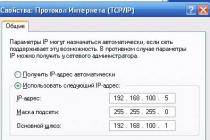
Hello to all blog readers. In this article, we will talk about how to restore system performance. Often users have the problem of a very slow computer, especially when recording and at reading disks, or simply unreasonable "brakes" of the system during operation or loading. Why the system freezes read
There can be a great many reasons for this, today I propose to consider a fairly common one - this is the wrong mode of operation CD/DVD - ROM or hard drives, i.e. let's talk about PIO and DMA.How to check the hard drive for errors and fix them read
What is the essence and difference between PIO and DMA.
PIO and DMA- these are two modes of operation of hard drives, in the general case of any drive.
PIO (Programmable Input/Output)- already outdated mode, it needs to work
engage CPU, resulting in a significant loss of performance.
DMA (Direct Memory Access)- a modern method that bypasses the processor and
draws directly to RAM, this allows significantly increase productivity and get rid of annoying "brakes".
DMA mode in various versions has long been used in Windows 7, 8, and 10 operating systems, however in Windows XP, a situation often occurs in which DMA automatically switches to PIO and it will not work to bring it back by conventional methods. What is causing this situation?
Implemented in Windows XP mechanism error control, if errors occur too often when reading from a hard disk or other drive, the system automatically switches to a slower mode, where their percentage is less. However, Windows XP can transfer a normally operating device to this mode.
How to fix errors
Windows read
And so, let's check the operating modes of all drives so that the system does not slow down ..
1 . Launching the console "Computer Management"- right click on "My computer"

in the drop-down menu, select the item "Device Manager", or through
Control Panel. Or Start - Run - devmgmt.msc
2. Choose " Device Manager", choose IDE ATA/ATAPI controllers,

several lines with controllers will open - we are interested in :
Primary and Secondary channels IDE→ go one by one to properties these channels (right-click on the channel, line " Properties”), to the bookmark “ Extra options",
there are two groups here "Device 0" and "Device 1", each has lines
"Transfer Mode"- must be selected "DMA if available”, then the line "Current transfer mode", should be something like "Ultra DMA mode: 4,

if "PIO mode" is set here, then this is just our case and we will fix it.
If everywhere worth mode ultra DMA, then you are all right and you can not continue further actions.
3. To begin with, let's try to fix it manually - in each line "Transfer mode" set "DMA, if available", press "OK" and restart the computer. After switching on again
we look at the operating modes of the channels, if DMA is everywhere, then everything is in order, if PIO remains, then we continue on.
4. Find again Primary and Secondary IDE Channels and delete them (right-click on each channel, in the list select "Delete"). Don't be afraid, everything will work fine.
Restart your computer again - Windows XP will find controllers and put them into fast mode, i.e. in DMA. Check the result, there should be a mode everywhere DMA.
5. If all of the above did not help and you again see “ PIO mode", then it will be necessary rearrange drivers for the motherboard - reboot
and check the result again.
6. Well, the last point, if after all the suffering the regime PIO never disappeared, then you have to edit in register. I want to note - perform any operations with
registry very carefully and carefully, any wrong action can lead to the complete inoperability of your system. It is best to make a copy of the registry in advance.
How to configure Windows XP using the registry read
First, try disabling the error control system.
To do this, in the registry branch:
HKEY_LOCAL_MACHINE\SYSTEM\CurrentControlSet\Services\Cdfs\,
create a key ErrorControl and set its value to 0.

After that, reboot and follow the step №4.

in it you can manually set the mode DMA.
There are several folders here. - 0000, 0001, 0002.
0000 - responsible for the controller itself;
0001 - responsible for Secondary IDE Chanell;
0002 - responsible for Primary IDE Chanell;
Open the folder for the channel we need. In it are
several keys, to begin with, select:
MasterDeviceTimingModeAllowed
SlaveDeviceTimingModeAllowed
and set the value to 0xffffffff.
After that, we set the value of the following keys:
MasterDeviceTimingMode
SlaveDeviceTimingMode
according to the following data, depending on
supported UDMA - mode:
UDMA Mode 2 - 0x2010
UDMA Mode 4 - 0x8010
UDMA Mode 5 - 0×10010
UDMA Mode 6 - 0xffff
After that, reboot and check the result - everything should work fine.
How to speed up and restore the performance of Windows 10, read
What is the speed of information transfer in computers, read
I hope this article will help you set the modes correctly. PIO and DMA and improve overall system performance.
Secondary Master
options-menu to assign each of the possible four hard drives (E) IDE-interface optimal PIO-mode (Programmable Input/Output). Possible values: "Auto" (default), "Mode 0", "Mode 1", "Mode 2", "Mode 3", "Mode 4". Modes 0...2 refer to ordinary IDE drives (ATA standard), 3 and 4 to EIDE (ATA-2), mode 5 to ATA-3. It is clear that in automatic mode the system will select the best data transfer speed for each of the disks. But we must remember that the automatic setting of the PIO mode is performed in accordance with the possibility of auto-detection of the functioning of the hard disk and the amount of information received from the device. If the user has doubts about the correctness of the auto-detection of the PIO mode, then, in accordance with the documentation for the hard disk, the user can change the PIO mode for any of the disks. The BIOS in "Auto" mode may also incorrectly identify the PIO mode of the EIDE disk, and the latter is not recognized. Modes 3 and 4 require the use of EIDE disks in the system.
Similar (four!) options may also be called " IDEPrimaryMasterPIO" etc.
Option " Fast Programmed I/O Mode(s)" offers the following values: "Disabled", "Auto detected", "PIO0", ... "PIO4". The option with the same name unexpectedly suggested the values "Disabled" and "Auto Detected" (default). speed characteristics less than optimal, "Auto Detected" sets the maximum possible speed.
The option may also be called " Mode PIO Transfer Data" or " Transfer Mode". The last option offered the following set of values: "Auto", "Default" (equivalent to "Fast PIO 1"), "Fast PIO 1", "Fast PIO 2", "Fast PIO 3", "Fast PIO 4", " FPIO 3 / DMA 1", "FPIO 4 / DMA 2". It is clear that each time we are talking about the parameters of four hard drives, or two for older systems. In this case, the options can be called " IDE Master PIO Mode" ("Master Drive PIO Mode") And " IDE Slave PIO Mode" ("Slave Drive PIO Mode").
PIO (Programmable Input/Output - "programmable input / output") is carried out by the central processor and works by transferring data to certain input / output addresses (see the "Ports" subsection). The PIO modes determine how fast data can be transferred between the drive and the controller. When they are used, the registers of the central processor of the system are involved. But that's not all! The PIO or DMA modes determine the size of the packets of transmitted information, the way they are encoded, the speed and sequence of transmission, all the time characteristics of the exchange cycle. Depending on the modes, different cycle times are set, so the transmission rates can vary over a very wide range (see table).
When receiving the "Identify Drive" command, the drive returns, among other parameters, information about the supported PIO and DMA modes. These parameters can also be determined using special utilities. The transfer mode is set by the value of one of the registers - SC (register of the sector counter of ATA devices). Through one of the modes of operation of this register, the exchange mode is controlled.
ATA-2 modes (PIO 3 and PIO 4) use hardware flow control. To be specific, the Enhanced IDE includes operations called "IORDY flow control" that allow the drive to enable burst mode for 100% bus bandwidth usage. The flow control mode transfers the initiative to the device (disk) and allows you to get rid of inefficient "blind" PIO modes by setting the controller bandwidth in accordance with the capabilities of the hard drive. This means that in those cases where the entire strip is available, the hard drive will manage the data exchange with the host adapter.
What is this signal? "IORDY" (Input/Output Ready) is a signal from the EIDE hard drive confirming the completion of the exchange cycle with the controller. Other names are "CHRDY", "IOCHDRY". The use of "IORDY" allows a high-speed hard drive to delay the exchange cycle with the controller when it does not have time to receive or transmit data. This makes it possible to reduce the standard duration of the exchange cycle to a minimum, increasing the speed to the maximum, and, if necessary, lengthen individual cycles using "IORDY". For this, the signal must be supported by both the hard drive and the controller. Disk-side flow control is enabled by the controller using the "Set Features" command, as a result of which such an exchange is supported simultaneously by both the disk and the controller. Controllers that do not support "IORDY" may cause data loss when using fast PIO modes; in this case, you should use lower speed modes. Mode 5 is mentioned in some sources, but it has not received distribution and is not standard.
If it is impossible to program the exchange modes individually for each of the devices in the system and when connecting devices that work optimally in different modes, the system will set the exchange at the rate of the minimum of the modes. Hence, the standard recommendation is not to connect a hard drive and a CD-ROM to the same channel.
Programmable I/O modes are only effective enough in single-tasking environments. For multitasking OS, DMA modes are more preferable. It must be remembered that high-speed DMA multiple transfer modes are implemented by operating system drivers. The software configuration capabilities of the driver determine the flexibility to control DMA modes.
A long state of stability sooner or later breaks something unpredictable and strange, so this moment has come. A couple of days ago, while copying a file from one physical disk to another, I suddenly noticed that the speed was catastrophically low - 4-6 Mb/s instead of the expected 50-90 Mb/s (corrected for fragmentation). I look at the CPU load - one core is fully occupied with interrupt processing, everything is clear - the disk has switched to PIO mode.
Initial configuration: ASUS P5Q, 4 x 1 Gb SATA drives, 2 x 1.5 Gb SATA drives, no RAIDs, Windows XP SP3. The disk worked in UDMA mode, like all the others, I tested it after installation. Device Manager –> IDE controllers –> channel and look at “current transfer mode”. In the picture, both devices work in UDMA mode, in my case the second device worked in PIO mode, but I did not save this picture. To understand who hangs on which channel, switch the Device Manager view to View –> Devices by Connection.
Although the drives are SATA, the controllers in Device Manager are ATA. The fact is that in the BIOS SATA controllers are configured by default to pretend to be ATA controllers, in which case additional new AHCI drivers are not required. You can switch to AHCI mode painlessly, it does not affect the logical organization of data, it only requires the appropriate drivers. In AHCI mode, support for NCQ (reordering of HDD commands) appears and, in general, performance grows a little, but not much, and hot-swap support is also added.
Versions of possible causes:
1) Something with a train.
2) Something with the drivers, failure or conflict.
3) Something with HDD.
There is a second system - Windows 7, I boot into it and observe the full performance of disks in UDMA modes, which means that the hardware seems to be normal. I look at the event log, I don’t find any messages about a problem with disks, I look at SMART diagnostics - everything is OK, there are no device conflicts, everything is fine. I take the latest drivers from ASUS. I write down the old version number of the Intel ICH10R driver, and install a new one. It is put suspiciously quickly, as a result it was not updated. I manually update the ICH10R drivers via INF files, it is installed, but the problem remains. I go to Intel, download the latest version, install it, nothing is installed again. I find out that their drivers are updated only if the device does not have a driver at all, to force it is necessary to use the secret key “-overlall”, I try, update, but does not solve the problem. I change the cable, take it out, stick in the disk - it does not help. The intermediate result is that the hardware works, the new software does not help.
I find an interesting article in Microsoft: “After several CRC errors or timeouts, IDE ATA and ATAPI drives use PIO mode” . They write that if there were transmission failures via UDMA, then the system sequentially lowers the modes up to PIO mode (or immediately) and freezes this state! To return back, they suggest deleting the controller from the Device Manager and it will be reborn from the ashes. I did not go for this, because. I was afraid that he might not be reborn (they wrote about it somewhere), so I went the second way described there and in other places.
Solution. Open the registry branch “HKEY_LOCAL_MACHINE\SYSTEM\CurrentControl lSet\Control\Class\(4D36E96A-E325-11CE-B FC1-08002BE10318)”, it will contain branches 0000, 0001, etc. They correspond to devices in the Device Manager. We are only interested in channels, we look at the name by DriverDesc, in this case “Primary IDE Channel”.

Pay attention to MasterDeviceTimingModeAllowed and SlaveDeviceTimingModeAllowed - they set the mask of allowed modes, if 0xffffffff, then everything is allowed, and if 0x1f, then only PIO mode. I have a problem on Slave. The current modes themselves are stored in MasterDeviceTimingMode and SlaveDeviceTimingMode, they are different (you can find the meaning of the numbers on the net). MS suggests doing the following - set an additional key ResetErrorCountersOnSuccess (DWORD) = 1 and reboot. I did that, but it didn't work, it just reset the desired UserSlaveDeviceTimingModeAllowed to 0x1f too. I returned it to the Device Manager, but I think you can manually set 0xffffffff here too. Next, I set SlaveDeviceTimingModeAllowed = 0xffffffff, rebooted and voila!, it all worked. In total, I think it was only necessary to do the following (the problem is on the Slave):
UserSlaveDeviceTimingModeAllowed = 0xffffffff, SlaveDeviceTimingModeAllowed = 0xffffffff, ResetErrorCountersOnSuccess = 1 and reboot.
The following picture shows the final state of the registry after a reboot. The modes are now the same, the masks are preserved and in the Device Manager we see the picture, as at the beginning of the post.

Now for the reason. As follows from the MS article, one of the reasons for fixing their driver was that the HDD start timeout was insufficient (in Win2000 - 4 sec, made 10 sec) and this was a problem in case the disks came out of sleep. I constantly used the setting to turn off disks after inactivity after 2 hours, which sometimes led to their fan waking up when some applications wanted to climb several partitions at once. I believe that maybe in some scenario the timeout was still exceeded and a failure was recorded, which led to the disabling of UDMA. Now I refused to turn off the disks, let them work, besides, frequent turning on and off may do more harm than good.
To transfer data between the hard drive and PC memory, two main modes are used:
program input/output mode (Programmed Input/Output, PIO);
Direct Memory Access (DMA) mode.
pio mode
In PIO mode, each byte of information from the hard disk is first read by the central processor and only then is written to the RAM. Depending on the duration of the read cycle and the number of sectors transferred per disk access, there are PIO modes (PIO Mode 0), PIO1, PIO2, PIO3, PI04, PI05.
dma mode
PIO modes are used in single-tasking operating systems when the computer's processor reads or writes data to the buffer memory of an IDE or EIDE hard disk drive, and then this data is transferred to RAM. In multitasking operating systems, it is advisable to use Direct Memory Access (DMA) modes. Input/output of data in this mode is carried out in the RAM of the PC without the participation of the CPU. This process takes place under the control of the hard disk drive controller in the pauses between CPU accesses to RAM, which somewhat reduces the data transfer rate, but saves processor time. To implement DMA modes, unlike Ryu, both special controllers and drivers are needed.
DMA modes are divided into single-word (Singleword) and multi-word (Multiword) depending on the number of words transmitted in one cycle of operation with the system bus.
Serial data (sata)
A further increase in the data transfer rate through the parallel ATA interface caused technical difficulties. In addition, PC manufacturers were not satisfied with the wide 40-core (or 80-core) cable, which prevents air circulation inside the case and is limited to a length of 46 cm.
Therefore, in 1999, the Serial ATA Working Group was created, the purpose of which was to create a serial ATA interface - Serial ATA (SATA). The interface was introduced in 2001 and demonstrated a data transfer rate of 150 MB/s.
In addition, to connect several devices (HDD, CD-ROM, DVD-ROM drives, etc.), not a star topology will be used (when each device must be identified as Master or Slave), but a point-to-point topology, when each device is directly connected to the host adapter (like SCSI devices).
SCSL (Small Computer System Interface) is a more versatile and efficient interface than an IDE. However, its hardware implementation is significantly more expensive than that of the IDE interface. The SCSI interface has clear advantages when working with video, as well as when using a CD-ROM drive in a multitasking operating environment or as a network drive.
Communication between a SCSI device and an I/O bus (such as ISA, PCI, VLB) is done via an external bus using a Host adapter. Devices connected to the SCSI bus do not interact directly with each other, but through the built-in SCSI controllers.