Despite the presence on the market of a fairly large number of companies dealing with “Smart Home” systems, most of them require deep integration into the existing electrical system of your apartment, house or office. The prices for such devices from renowned manufacturers are also not encouraging, in especially neglected cases you will have to part with a four-digit amount for one thing. remote control lighting. And I'm not talking about rubles or hryvnia.
But in the past few years, the situation has begun to change dramatically. One after another, companies are born that offer home automation systems with good functionality at tasty prices. The company "" producing lighting control devices since 1997 provided me with its Mini Kit "Smart Home in 1 Hour" for review, which I will try to talk about today in the most accessible form. Looking ahead and in order to avoid premature comments, I will say that recruiting from a Belarusian company will not turn your home into a truly "smart" one, but at least it will allow you to get one step closer to this goal.
The text can and probably does contain grammatical, spelling, punctuation and other types of errors, including semantic errors. I ask readers in every possible way to point out these errors and correct me through private messages.
▌About the company's products and the monitored set

Now Nootechnika sells two kits for self-installation: Mini and Maxi Kit. The latter is distinguished by the ability to manage more load groups and is equipped with additional temperature / humidity and motion sensors. I got the Mini Kit and it consists of:
The red wire extending outside the housing is a jumper that determines the mode of operation of the unit. Initially, the unit operates in relay mode, i.e. just turns on and off the load. Breaking this connection puts the device in dimming mode, which makes it possible to adjust the power of the corresponding devices (incandescent lamps, heaters, fans, etc.).
The "SU" type units have appeared on the market quite recently, before that the dimmable (SN, ST) and "relay" (SL) units were sold as separate devices. There are only 5 models in the SU series, which differ in the maximum switching power: 0.2, 0.3, 0.5, 3, 5 kW. There are also modules included in the phase gap (SB series), waterproof blocks for outdoor use (SR series) and a controller led strip(SD series). The catalog of power units with prices can be found on the official website of Nootechnika, there are also all existing models and for the SU111 series of units.
Switches (radio transmitters)
The delivery set includes two remote controls: PU311-2 and PU313-2. The company has a great variety of remotes, although in fact there are only 3 structurally different versions plus a remote control. The PU series has two revisions, which are designated as the prefix "1" and "2" at the end of the name. These are switches with touch-sensitive keys in white or beige color and they differ primarily in the functionality of the keys themselves (they are not universal, despite the fact that they are touch-sensitive).
The working area of the remote control is matte to the touch, and the frame, which is its basis, is made of glossy plastic. In the left upper corner there is an indication LED, which is activated each time one of the buttons is pressed.

The remote control is powered by CR2032 batteries. Guaranteed time autonomous work remotes is 1 year, but in reality it should turn out to be much more. On the official website of the company, when using the remote control 48 times a day (with a standard battery capacity of 210-240 mAh), the remote control will last for 3.8 years, taking into account the self-discharge of the battery. 1 year guaranteed. the maximum declared range (50 meters) remains in the first 1-1.5 years of operation. As such, the remote control does not have an indicator of a discharged battery; subsequently, it will be possible to determine a dead battery by a dimly glowing indicator at the time of command transmission.
There are one-, two- and three-channel remotes. An unlimited number of power blocks can be linked to each channel. The main thing here is not to get confused, since only up to 32 remotes can be tied to the blocks. The maximum range of work in open space is 50 meters. I experimented with the range and here's what I can say: the unit receives and executes commands at the stated distance, provided there is a line of sight from the window of the room in which it is installed. With reinforced concrete floors, everything is a little more complicated: at the entrance of a panel high-rise, a block is enough for 2-3 floors, the signal no longer passes. Of course, there are no problems within the apartment.
The third version of the remote that I mentioned at the beginning is. As such, there is no switch in this case, there is only a transmitter unit for connection to return (push-button) switches. Here is the tactile response desired by many and the ability to use switches of any design you like. Remote control, a variety of wall switches and their cost can be contemplated at.
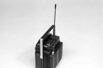
Ethernet gateway
It is connected to the local network and is an intermediary between the nooLite system and computers or mobile devices. It looks like a small black box with an external antenna. The package contains a power supply unit and a patch cord for connecting it to a router or modem. An album with additional photos, including images taken during the preparation process, can be found at.
The Ethernet gateway does not have direct access to the Internet and works in local network... He also does not know how to request a DHCP address and is available only at 192.168.0.168, which can be changed to another one during subsequent configuration. I can't help but note that regular user there may be problems connecting this device, especially if the given static address is already in use by someone on the subnet. But I'll talk about this later.
PM111 motion sensor
Was purchased separately in order to equip one of the rooms with automatic lighting control. In terms of size, it is identical to the wall switches included in the Mini Kit, and in terms of its functions, it resembles them altogether, because simply sends an on and off command to the pre-assigned power unit. An album with additional photos, including images taken during the preparation process, can be found at.
The PM111 is powered by two AAA batteries (included), and their charge should be enough for at least a year of operation. When the charge level is critical, the LED located under the lens of the thermal sensor will notify you with three short flashes every 8 seconds. On the rear panel there are three trimming resistors for setting: the threshold depending on the illumination (1 ... 100 lumens), the shutdown time after triggering (5s ... 21.8 minutes) and the sensitivity of the sensor. Parallel operation with any nooLite remotes is supported. For information: sensor in and it.
▌Installation and configuration using the example of your own home
The most interesting thing is the installation. I am a little afraid of electricians, despite the fact that I am friends with electronics. For reasons unknown to me, she sharpens her grudge against me and as soon as the opportunity arises, she tries to show her superiority. This time there were no incidents, it is really possible to install the set in an hour, if everything is planned and prepared in advance.I will show the installation using the example of the apartment in which I now live. This is a rented apartment, the owner of which agreed to install the system and my subsequent "entertainment" with the apartment, provided that everything will return to its place at the congress. We have an unremarkable one-room apartment in a panel house of the type with the following lighting scheme:

The model was created in the program. Ceiling chandeliers were replaced with lamps for clarity
Even before receiving the kit, it was decided to purchase a motion sensor and an additional power unit, since one of the light sources in the case of using the Mini Kit in its "pure" form would lose control. As a result, the application scheme took the following form:

By default, instead of the fourth block, block # 3 is tied to the third channel of the remote control, but for experimental purposes it was decided to swap them. The linking / unlinking process is quite simple and is described both separately and fully-fledged for the entire system. The second and third channel of the consoles control the light in the bathroom and corridor, which in fact is a clear example of implementation pass-through switch, only without wires.
I started connecting the power units from the living room, having previously de-energized that part of the apartment's electrical network that is responsible for lighting. Additionally, I recommend getting an indicator screwdriver (if not already) to check the lack of potential on the lines with which you are going to work. The process of dismantling the chandelier did not cause any difficulties, but the obscenely twisted wires, although they did not surprise, still left a certain residue.
 An album with additional photos, including images taken during the preparation process, can be found at.
Two white wires leaving the unit are connected to the mains, and two black ones to the subsequent load. For connection, the kit includes a set of 12 WAGO lever clamps. If you still twist, then stop immediately, I advise you to at least read here on Geektimes and the comments to it (there is valuable information on another such article).

Both single and stranded copper wire can be clamped into the "Vag" terminals. I learned this fact already in the process of writing the article, so the stranded wires from the chandelier were pre-tinned. I cleaned the conductors sticking out of the ceiling to remove any oxides that had formed on them.

The block did not fit into the bowl of the chandelier, so it was left outside. If there was a neutral wire in the junction box of the old switch, then it would be possible to place the unit there or be a power unit in the set. The antenna of the unit (white wire) must not be cut, twisted or hidden in metal bowls to avoid shielding.

In the kitchen, the block also did not fit into the plastic cover of the "chandelier". Yes, in quotes, because this is a stupid wire with a cartridge on which a hefty white cap was previously put on, absorbing a huge part of the light flux. It's time to lobby for the purchase of normal lamps. In the bathroom and corridor, similar steps were taken to install the power blocks.

For absolutely all points, 300-watt blocks are redundant, since I use 20-watt luminescent energy-saving lamps. In the living room, the total power consumption is 60 W. Even taking into account the double power reserve recommended by the manufacturer (especially when placed in places where air convection is difficult), such units are still redundant. With incandescent lamps comparable in luminous flux to those installed by me energy saving lamps the situation would be diametrically opposite. Most likely it will not fail, but it will feel very "hot".
Installation of switches is much easier than connecting power blocks. They can be placed as you like and anywhere, except for mounting on metal surfaces. By default, the backplate is installed using self-tapping screws or pre-applied strips of tape.

We remove the old switch and, using all the same WAGO terminals, we close the wires as if the switch was on all the time. As it turned out, the junction box in the case of this switch is simply absent and the latter was inserted stupidly (just stupidly) into the drywall slot.

Yes, the yellow-green wire is the phase for connecting the corridor lamp. Sad, isn't it?
The native strips of scotch tape are too small for the resulting hole, so my favorite double-sided foam tape was used. Now I am afraid that during the subsequent dismantling, I will tear off the mounting frame with a piece of plasterboard wall.
 An album with additional photos, including images taken during the preparation process, can be found at.
That's it, one switch is installed and ready to use. With the second one, at one time I rushed around the room deciding where to place it - by the bed or in the same place near the sofa. In the photo below, during experiments, it was installed along with a stationary switch, which was later finally dismantled.

But the remote control by the bed is also convenient, despite the ability to control the light from a watch or smartphone. Therefore, the purchase and installation of it is just around the corner. At the moment, the lighting control scheme looks like this:

Where B - blocks, P - remotes, and D - motion sensor. The latter, similar to the remotes, can be mounted on self-tapping screws or double-sided tape. For a start, a small piece of adhesive tape is enough, as you will most likely have to play around with the sensor placement. At the maximum set sensitivity, the angle of its view, revealed experimentally, reaches 120-130 degrees, and the operating range completely covers my kitchen (2.5 x 2.5 meters). After some experimentation, the sensor was placed on one of the kitchen drawers so that it was not affected by the local cooking lighting and the extractor hood lamp above the stove.

At the moment, the sensor is located on the right side of the handle
The sensor is triggered instantly, but a slight delay is still present due to the fluorescent lamp - it does not turn on immediately. I set the shutdown time to about 10 minutes. The sensor, it seems, should check for the presence of movement before sending the shutdown command to the unit, but I either freeze at these moments, or the sensor simply does not notice me. As a result, the light goes out and you have to wait 4-5 seconds to re-check the presence of movement. The illumination threshold was set to 30% of the state when the sensor is always on and monitors movement. At this level, triggering occurs even on especially cloudy winter days, which is what I tried to achieve.
As for the snag about this sensor that I mentioned earlier. Imagine that, in addition to the sensor itself, the controlled unit is tied to a wall-mounted remote control for manual control of lighting in the kitchen, as in my case. Neither sensors nor remotes have feedback and if the light in the kitchen turns on as a result of the motion sensor, and you turn it off using the remote control or the web interface, which will be discussed below, then the motion sensor will continue to think that the light is turned on with its help and will continue to count down the preset 10 minutes, to send a command to turn off the light. Got the point? If you re-enter the kitchen after turning off the light manually, the sensor will not work. Therefore, I untied this block from all consoles, including the scenario channel "Turn off all", since the motion sensor itself is able to turn off the light in the kitchen in the absence of movement.
Scripting channels are an interesting topic. In the Nootechniki catalog you can find both consoles with one script key, and with all three. Scenarios allow you to control an unlimited number of blocks (this is the basic feature of the remote control): turn them off all at the same time, turn on the corresponding block to a preset level of brightness or color (for an LED strip), or turn on the required group of lamps. Only one action can be performed with one channel, i.e. turning on and off a group of lamps with one key will not work. More about the scripting capabilities can be found in (chapter 6) for the entire nooLite system. In general, before buying, I recommend that you familiarize yourself with it - this will save you from most of the questions.
Ethernet gateway, control from mobile devices and Pebble watches
So far, I will only talk about the basic capabilities of the gateway. Information about the API and its integration into other Smart Home systems deserves a separate article. During installation, the manufacturer recommends that the router and Ethernet gateway be separated by at least half a meter, because wifi signal network interferes with signal reception in temperature / humidity sensors. Of course, there are no latter in the younger set, but why not play it safe for the future?
Special thanks to the developers for the green indicator (!) LED, and not the torn-out blue spotlight, which Chinese manufacturers like to use (the next Xiaomi, despite the blue LED, is an exception).

The first connection to the local network was not crowned with success. Firstly, my network is built on addresses like 192.168.1.x, which already made the gateway impossible to work. Okay, we transfer the subnet to 192.168.0.x, but nothing still happens, you can't go to 192.168.0.168. I assume that this network address is already occupied by some of the home devices and I directly connect the gateway to the computer via a patch cord. I assign the address 192.168.0.1 to the computer with a subnet mask of 255.255.255.0.

That's it, now there is an opportunity to go to the gateway and even play around with turning the lights on and off. We recommend that you first upgrade to the current software version and change the standard gateway address to the one allocated to it in the settings of your router. detailed instructions there is a flashing in - I see no reason to repeat it once again. There is already a third version of the software, but the second is current and stable, while the gateway itself comes with the first version. The web interface is updated separately from the update. software and is the second step in the overall upgrade process. The firmware itself can be downloaded from the Nootechnika website.

The main innovations of the second version are the authorization setting, which previously did not exist at all (any person in the local network could control the lighting knowing only the gateway address), the functions "Dawn" and "Sunset", about which later, and, in fact, the ability to "forward" the required port to access the gateway from the external network. To do this, you need to have an external static IP address (as a rule, you can order from your provider, rent costs about $ 1-2 per month) and perform a set of simple manipulations with your router. Instructions on this topic are in the archive with the files for updating.
The main function of the gateway is to mediate between devices on the local network and the radio lighting control system. The gateway, unsurprisingly, copes with this task. On start page the web interface displays blocks pre-associated with the gateway and pre-installed scripts.

Inside the menu item responsible for a specific block there are two buttons and an impromptu LED. In the case of dimmable blocks, a "slider" is added to the page to set the desired lighting level.

In addition to the scenario "Turn off all" there are functions "Morning" and "Evening". All of them are independent and are not synchronized in any way with the scenario channels on the switches due to the absence of any feedback.

Writing a script is easy enough. Need to turn on, turn off or set to certain power all the luminaires that you want to use in the scenario and click the "Save" button. Thus, you can create any scenario, for example, "Watching a movie", when the lights in the whole apartment are turned off, and a sconce or something like that is activated near the bed at minimum power.
In addition to scripts, it is possible to set 8 weekly timers (icon in the upper right corner) and use them in scripts. Here you can recall the functions "Dawn" and "Sunset" added to the second version of the software. With the help of weekly timers, you can set, for example, that from Monday to Friday at 8 am the "Dawn" actions will be performed, as a result of which the selected group of lamps (the scenario, in fact) is activated with a smooth increase in brightness. This mode will work only in the case of using dimmable lamps and correspondingly configured power units.

In principle, that's all, this is where the main possibilities for controlling lighting from a gateway via a web interface end. Information about connecting sensors and working with them is in the user manual, which I already have.
In general, the interface does not look very good on computers with large monitors since originally designed for mobile devices. Applications for, and, in turn, are stripped-down versions of the web interface, since there are no opportunities to create timers, scripts, bind and unbind blocks, and much more. To enable or disable the load in the case of an Android client, slide switches are used. Already created scripts can be rewritten directly in the application.

After a whole month of operating the system, I never once used the web interface, simply because there was no need for it. Using my smartphone, I played with the light several times to demonstrate the system to friends and a couple of times in bed when the clock was on the table. With respect to the clock, everything is completely different. I resorted to their help every time I forgot to turn off the light with the switch. Yes, in the future I will most likely add another remote control near the bed (for a girl, for example), but so far they are doing quite well with this task.
As for the application for Pebble itself, it is quite justified by Vlad Zaitsev (vvzvlad) when he talked about the excursion to the production facilities of the Nootekhnika company. Later I got used to the logic of the application in just a couple of days, so you can still use it. There is also an Apple Watch app, but I don't have an Apple Watch, so I won't show it to you.
▌Why do I (you) need this? Application of the nooLite system
Along with the solutions used in my apartment, I will show some more examples of using this system.1. A banal opportunity to place switch anywhere in the room: by the computer, bed, near the sofa, or even on the window. No wiring needed. It is enough to purchase a power unit with a double power reserve and any remote control you like. More on this.
2. Pass-through switch... most often used in corridors, where one switch is installed at the beginning of it, and the other at the end. The person who entered the corridor turns on the light with the first switch, and at the exit switches it off with the second switch. Have you considered how many wires you need to lay in the wall? And if you add another switch?

One power block and two switches completely solve this problem. In the case of a completed renovation, it will be even cheaper than re-chipping the walls.
3. Use in wooden houses where there are special requirements for the installation of electrical wiring. For those who did not know hidden wiring in wooden houses, at least it is not recommended, and in the case of using corrugated PVC pipes, it is completely prohibited. In general, the standards for wooden structures are quite strict and those who adhere to the rules and fear for their lives will have to spend either on good hidden wiring in metal sleeves, or to cover a beautiful tree with a 10 mm layer of plaster and lay the wiring under it. In the case of open wiring recent times The so-called "retro-wiring" using stylized cables and ceramic insulators is gaining popularity. The solution is beautiful, but far from the most practical, time-consuming and costly.
4. Wireless motion sensor for automatic control lighting... Of course, I would like to see more sensors in various form factors in Nootechnika's arsenal, but even what we have already allows us to automate the lighting in the apartment and save on electricity. The main advantage of the monitored sensor is the absence of wires. Usually, these devices are included in the break of the phase conductor of the luminaire and additionally require zero for power supply. Those. both installation and subsequent movement of the sensor in case of unsuccessful placement are complicated. More on this.

5. Light control from watches, computers and mobile devices located in the same local network. You can, of course, get worn out and buy a static IP address from the provider, forward the port to the Ethernet gateway and completely control the lighting from anywhere in the world, but given the lack of feedback from the nooLite system blocks, the rationality of this solution, in my personal opinion, comes down to zero.
I'm afraid if I continue to describe all sorts of scenarios, I will go beyond the limit on the number of characters set on the site for one article. More examples the use of devices from "Nootechnika" is on their website. And yet, I know that a similar control can be implemented on the Arduino or even by assembling an independent device, so there is no need to write about it in the comments. It is better to calculate how long this will take for you, and then multiply by the cost of one of your hours. If this, of course, is not your hobby, but your wife, children or flatmates will be able to put up with the lack of light due to the debugging work you are doing.
- How convenient are touch switches? How to be in the dark? Is there any backlighting?
No, there is no backlight, in the dark you will have to navigate by touch. It was more convenient to do this in the switches of the first revision, since the buttons could be felt in the corners of the frame. In the second version, I periodically miss the center key. As such, pitch darkness in my house does not happen, either a table lamp or a night light is always on, and given my beloved “creative mess”, with all my courage I will not dare to move around the apartment in the middle of the night without, for example, a smartphone. If desired, you can change the touch switches to return ones using the remote controls.
- Can I turn on the light with my left toe in warm socks?
You can either left or right, but either in thin conductive socks, or without them at all. And you can also use your nose, yes. I'm not kidding, as such situations happen.
- What happens if the lights are turned off in the apartment? Will the blocks lose their binding? What state will they be in after the resumption of power supply?
Nothing will happen. In the event of an emergency power outage, the blocks will not lose their binding, since all information is stored in non-volatile memory. If we talk about the units of the SU series supplied in the kit, then they do not have the function of storing the state when the 220 V network is lost. For other models, see the company's website.
- Is it easy to hack into the system and gain control over the control of lights and electrical appliances?
Easy enough, because the system does not have any serious protection. And if you have an open Wi-Fi network and you are using an Ethernet gateway with the first version of the software, then any "passer-by" will only need to connect to this network and go to the standard gateway address 192.168.0.168. For radio control, only 16 bits of the address are used, respectively, the enumeration of possible 65536 combinations will take a few hours. Any protection of the proprietary protocol is also absent, the signal from the remote control is easy to "catch" and record. There was even an article on Habré about. The question is, who might need to "hack" the lighting control system in an average apartment or house? Except for some dirty schoolchildren, but they usually welcome other methods.
- How to predict when the batteries in the remote control will run out? I would not want to be left in the middle of the night without the opportunity to turn on the light.
I have already raised this question higher in the text, but still I will repeat myself, since it arises really often. As such, the remote control does not have a discharge indication, but as the critical charge level is approached, the indication LED will glow dimmer and dimmer when transmitting commands. This is an indicator that it is time to replace the batteries. If during this time you do not bother to replace the batteries, and you will not be at home (as a person who can replace the battery in the remote control) or, in fact, CR2032 batteries, then yes, there will be no way to turn the light on or off.
▌Results
If you have read this article to the end, then you are at least a hero, since I have not yet written such large materials. It is simply unrealistic to cover in one article all the variety of a seemingly simple system like nooLite, I'm afraid to imagine what would happen if I got a full-fledged smart home controller with a bunch of peripherals for review. Probably, it would be possible to divide the review into two parts, but then the text would have turned out even more. From this material, I excluded the chapter on the operation of the system at the data transmission level and the preparation of the main components, but I will definitely write it later.I can safely recommend the official site of Nootechnika as an exhaustive source of information for further study of the system. Almost every device has detailed guides, video and brief infographics. There, on the site, the system and its individual components are collected, so there will be no traditional heading "Related links" at the end of the article.
As for the system itself, not only does it deserve attention, it also costs its money. Hobby solutions based on Arduino and the like are still not plug & play devices and require painstaking installation and configuration, and advanced systems for home automation based on Z-Wave or X10 protocols will cost a lot more.
What we liked
- Basic system price (block switch)
- Easy to install and configure
- System extensibility
- Control from mobile devices in the local network (especially from the watch)
What did not like
- Lack of feedback, remotes and gateway are not synchronized in any way
- Gateway cost and functionality
What would I like
- Any protection (encryption of the data transfer protocol)
- Expansion of the possibilities of scenario channels (the ability to turn on and off the light with one scenario button, double tap for assignment additional functions) ,. On my website, I duplicate my publications from all over the Internet, so too. :)
Today I want to show you an interesting device with which you can control anything via the Internet with Wi-Fi assistance ESP8266 (ESP-01) module and ATmega8A microcontroller.
In this bundle, the module acts as a controller WiFi networks and a web server, and ATmega8A acts as a power node controller, receives a string using a simple protocol from ESP8266 and after processing it issues a command to open one or another relay through a shift register 74HC595 and transistor assembly ULN2003.
Device diagram:
Referring to the given IP address, default: 192.168.4.1, can be configured different modes and control lighting in an apartment or house. The device has a web interface. The firmware for the ESP8266 is based on "Web dumps" from a respected «
PVVX "... I just added a couple of three handlers in the file that when a certain line is received from the web side, a 4 byte line will be sent to the UART interface - the command identifier. There are two such commands for each control channel, this is to turn it on and off. Also, there are two additional commands that can turn on and off all lighting channels at once.
And then, by writing a simple web page, I can easily control the lighting of the apartment.
The device works as follows:
From the web: in a simple way, when you click on any of the buttons, a script is first called that changes the background of the button and changes the variable value from 1 to 0 and vice versa with each click and then the AJAX handler is called, which is processed by the program in ESP8266 and sent to the UART code corresponding to the AJAX command. And already ATmega8A, this line is accepted and processed.
From the microcontroller side: a string is received, processed, and if the string matches the test string, then the necessary actions are performed. It looks like like this:
Void send_data () (static char buff_data = 0, rel_data = 0; static char x = 0; if (string_search ("@ 1A00", rx_buffer)) // LIGHT ON kitchen (rel_data | = 0x81; printf ("1CH ON \ r \ n "); clear_buffer_rx (); x = 0; if (demo<42000 && demo_off==0) demo++; } .................... .................... else if(string_search("@2A00",rx_buffer)) // LIGHT OFF кухня { rel_data&=~0x81; printf("1CH OFF\r\n"); clear_buffer_rx(); x=0; if(demo<42000 && demo_off==0) demo++; } relay_send(rel_data); }
This function compares the incoming string in ewart, with a string that executes certain commands. If it matches, then the action is performed.
the uart parser function is self-made, here is its code:
Char string_search (char * str1, char * str2) (unsigned char addr = 0, x = 0, y = 0; str1 + = 0; str2 + = 0; while (str1! = 0) (addr ++;) while (str1 [y ]! = 0 && str2 [x]! = 0) (if (str1 [y] == str2 [x]) (y ++; x ++;) else (if (y The web page does not apply for an award, and looks like this: When you press any of the buttons, the lighting is turned on! The web page of settings is hidden from the main one and opens when you enter links. Below I will indicate them. If desired, anyone can modify the main page by adding a button or a link to it to go to the settings. 192.168.4.1/protect/wifi.htm For questions about updating the firmware, you can. Photo of the mounted device: Attention! Printed circuit boards were designed as universal (for general use) and used boards from what was already manufactured, this is all associated with a reduction in development time and savings in manufacturing costs for factory boards. Therefore, some nodes are not soldered for the task of lighting control. Good day, dear reader. A bit of lyrics at the beginning. The idea of a "smart" light switch is not at all new and, probably, this is the first thing that comes to mind for those who started acquaintance with the Arduino platform and IoT elements. And I am no exception. Having experimented with circuit elements, motors and LEDs, I want to do something more applied, which is in demand in everyday life and, most importantly, will be convenient to use, and will not remain a victim of an experiment in displeasure with comfort. In this article, I will tell you how I made a switch that will work like a normal switch (i.e., which is usually mounted on the wall) and at the same time will allow it to be controlled via WiFi (or via the Internet, as is done in this case). So, let's make a list of what you need to implement your plan. I must say right away that I intended not to spend a lot on components and chose components based on feedback on the forums and the price-to-quality ratio. Therefore, some components may seem inappropriate here for experienced electric lovers, but please do not judge strictly, because I am just a beginner in electromechanics and would greatly appreciate comments from more experienced professionals. The prices are taken from Ebay, where I bought them. And here's what the elements from the table look like: Now you can draw up a connection diagram: As you may have noticed, the circuit is very simple. Everything is assembled easily, quickly and without soldering. A kind of working prototype that you don't need to tinker with for a long time. Everything is connected by wires and terminals. The only negative is that the relay did not fit into the switch socket. Yes, initially I planned to cram all this into the wall behind the switch to look aesthetically pleasing. But to my regret, there was not enough space in the socket and the relay simply did not fit either along or across: So, temporarily, I took the relay out by the socket until I found a suitable switch box with an outlet to hide the iron inside. But there is nothing more permanent than temporary, is there? Therefore, it all looks like this now: Electrical tape will save you from electric shock ... I hope. Now let's talk about the software part. And before proceeding with the analysis of the code and details, I will give a general diagram of the implementation of the control of the light bulb. I hope someday I'll rewrite everything and the communication will be based on a faster protocol than HTTP, but for a start it will work. Remotely, the light bulb changes its state in about 1-1.5 seconds, and from the switch instantly, as befits a decent switch. Next, we need to connect the ESP to the computer, for this we need either a USB to Serial Adapter (such as FTDi , CH340 , FT232RL) or any Arduino platform (I had an Arduino Uno) with RX and TX outputs. It is worth noting that the ESP8266-01 is powered by 3.3 Volts, which means that in no case connect it to the Arduino, which is (often) powered by 5 Volts, otherwise everything will burn out to hell. A voltage reducer can be used as shown in the table above. The connection diagram is simple: we connect TX, RX and GND ESP to RX, TX and GND of the adapter / Arduino, respectively. After that, in fact, the connection is ready to use. The microcontroller can be programmed using the Arduino IDE. A couple of nuances when using the Arduino Uno: And here is the program for ESP itself: Show Code #include I used Yii for these purposes. I chose this framework for several reasons, I needed authorization (since the portal is available on the Internet) and role management (for future experiments), and I just like it. And now my control portal looks like this: To control a light bulb in the reach of the network, the server itself on ESP would be enough. But you want to have logs, logic and other devices in the future, so it's better to use a separate server for control. This is all about the portal, I think it makes no sense to write more about it, but if you have any questions, I will be happy to answer them in the comments. The technology of wireless data transmission in local networks Wi-Fi appeared in 1998 thanks to the engineer of the Australian laboratory of radio astronomy CSIRO John O'Sullivan. The first standard for the wireless communication protocol IEEE 802.11n was approved in 2009. During its development, Wi-Fi technology has gained widespread popularity, primarily due to the lack of the need to use wires when connecting to a network. And if initially Wi-Fi technology was used to connect wearable and handheld computers, then now this technology has penetrated into cameras, and into household appliances, and into multimedia devices, and into control devices. Wireless sensors of various physical quantities - temperature, pressure, humidity, etc. are widely used. Smart home monitoring and control devices equipped with Wi-Fi module mi, can carry out their functions from any point where a local wireless network is available, and if this network through a router has the ability to access the global network - and from any point where there is Internet. With the help of his smartphone connected to the Internet (via Wi-Fi or GSM), the user can not only browse sites, but also control household appliances located at any distance from him. The standard Wi-Fi network scheme contains at least one access point that forms a wireless network with a known identifier (SSID) and encryption parameters, to which at least one client is connected. An access point can be either a specialized device or a router equipped with a wireless radio module connected to the global network. Also, for example, a laptop or smartphone equipped with Wi-Fi modules and connected to the network using a cable or GSM technology, respectively, can act as an access point. In this review, we will look at some of the modules offered by Master Kit that use Wi-Fi wireless technology. Some modules are intended for use in DIY projects, come as a printed circuit board with components and do not have enclosures, while others are made as complete devices and are designed to be used out of the box. It should be noted that each of the considered devices is a client of the wireless network, therefore, an access point is required to connect them to the network. You also need to pay attention to which network the device connects to - local or global. Many Wi-Fi devices use portals located on the global network to communicate with other such devices and exchange information. This method of communication makes it possible to simplify the connection, since it does not require a permanent dedicated IP address of the global network and relatively complex network settings such as NAT (port forwarding) for external access to the local network located behind the router's firewall. For ease of comparison, the main characteristics of the devices are summarized in the table at the end of the review. Our review will begin with DIY-modules Master Kit using Wi-Fi technology. The device is based on the widespread Wi-Fi module ESP8266. The module is a microcontroller equipped with a wireless interface. It supports IEEE 802.11 b / g / n standards, with WEP and WPA / WPA2 encryption. The module also has 11 user-accessible I / O ports and wired communication interfaces SPI, I2C, I2S, UART and a 10-bit ADC. Several free development kits (SDKs) are available with a compiler and libraries to take advantage of the ESP8266's capabilities. All this made it possible to create a modern device for mobile control of various electrical appliances using smartphones or tablets. As already noted, the module is designed to work in local networks. If it is necessary to use access to the global network, then the following device will help with this. The Network Protocol MQTT (Message Queue Telemetry Transport) is a lightweight protocol for transferring data between devices and runs over TCP / IP. This protocol uses a behavioral messaging design pattern known as "publisher-subscriber", is very easy to use and administer, does not impose a heavy load on communication channels and works well when there are problems in these channels, and also does not impose restrictions on the format of the transmitted data. ... MQTT is designed for low-power embedded devices, so it requires minimal processing power that microcontrollers can handle. Thus, the MQTT protocol is, along with some other similar protocols, for example MODBUS or RS-485, an excellent tool for implementing the functions of the "Internet of Things" - IoT. Remote control of two relays, 2000 W each; Reception and transmission to the network of readings of two DS18B20 temperature sensors connected to it; Receiving and transmitting readings of DHT11 or DHT22 humidity sensors, analog sensors using the built-in ADC. But, in addition, it provides data reading from sensors and control of built-in relays via the Internet at any point, there is a connection to the global network. When working in the global network, a free MQTT server is used, by default, but another one can be used. The use of the STM8 microcontroller made it possible to implement a very wide functionality in a small volume. The module is, on the one hand, a complete device for collecting data on consumed household resources, such as water, heat, gas, electricity, and on the other hand, a multifunctional device for monitoring and controlling executive modules and mechanisms. The device collects data from the sensors and meters connected to it according to the established schedule and transmits this data to the server for further processing and use. Up to 8 devices can be connected to one device in any combination: Water meters; Gas meters; Electricity meters (when installing an additional CAN or RS-485 interface module); Temperature sensors, for example; Water leakage sensors, for example; Liquid level sensors; Gas leakage sensors; Actuators (shut-off and control valves with an electric drive), for example, a ball valve with an electric drive. When using additional built-in modules of RS-485 or CAN interfaces, in addition to the 8 devices listed above in the description, up to 8 Mercury-type electricity meters can be connected to one module, in addition to the 8 devices listed above. Modules can be combined to increase the number of served data collection channels. The device collects data from meters and sensors and transmits them to a server located in Russia according to the schedule set in the settings. In normal mode, data is sent once a day with hourly detail. If an emergency is detected (the water meter has turned off, a leak has occurred, the battery runs out, etc.), the device communicates immediately and informs the owner about it using PUSH or E-MAIL notifications. A personal account of each user is organized on the server. In your personal account, you can specify on what day and hour the server will automatically send readings every month. The readings can be sent in the following ways: in the form of a PUSH notification, in the form of E-MAIL, directly to the MOS.RU portal. Forget the hassle of manual monthly readings! Alternatively, you can simply view the readings and graphs on your mobile phone, tablet or computer using a browser or mobile application for iOS and Android. The module is powered by three alkaline (Alkaline) AA batteries, battery life is at least 3 years. When the charge level drops below 10%, a PUSH or E-MAIL notification will be sent to the user. The device communicates with the server using an Internet connection via a private or public encrypted Wi-Fi network. Two networks can be used: main and backup. In the absence of communication, the device collects and stores an hourly log for 1 month, when it is resumed, it transmits data to the server. In any abnormal situation (the device does not communicate, there is a leak, a break in the communication line to the sensor or meter, etc.), the server will send you a PUSH or E-MAIL notification. Despite the presence on the market of a fairly large number of companies dealing with “Smart Home” systems, most of them require deep integration into the existing electrical system of your apartment, house or office. The prices for such devices from renowned manufacturers are also not encouraging, in especially neglected cases you will have to part with a four-digit amount for only one remote lighting control. And I'm not talking about rubles or hryvnia. Now Nootechnika sells two kits for self-installation: Mini and Maxi Kit. The latter is distinguished by the ability to manage more load groups and is equipped with additional temperature / humidity and motion sensors. I got the Mini Kit and it consists of: The red wire extending outside the housing is a jumper that determines the mode of operation of the unit. Initially, the unit operates in relay mode, i.e. just turns on and off the load. Breaking this connection puts the device in dimming mode, which makes it possible to adjust the power of the corresponding devices (incandescent lamps, heaters, fans, etc.). The "SU" type units have appeared on the market quite recently, before that the dimmable (SN, ST) and "relay" (SL) units were sold as separate devices. There are only 5 models in the SU series, which differ in the maximum switching power: 0.2, 0.3, 0.5, 3, 5 kW. There are also modules included in the phase gap (SB series), waterproof blocks for outdoor use (SR series) and an LED strip controller (SD series). The catalog of power units with prices can be found on the official website of Nootechnika, there are also all existing models and for the SU111 series of units. The working area of the remote control is matte to the touch, and the frame, which is its basis, is made of glossy plastic. In the upper left corner there is an indication LED, which is activated each time one of the buttons is pressed. The remote control is powered by CR2032 batteries. The guaranteed battery life of the remotes is 1 year, but in reality it should be much longer. On the official website of the company, when using the remote control 48 times a day (with a standard battery capacity of 210-240 mAh), the remote control will last for 3.8 years, taking into account the self-discharge of the battery. 1 year guaranteed. the maximum declared range (50 meters) remains in the first 1-1.5 years of operation. As such, the remote control does not have an indicator of a discharged battery; subsequently, it will be possible to determine a dead battery by a dimly glowing indicator at the time of command transmission. There are one-, two- and three-channel remotes. An unlimited number of power blocks can be linked to each channel. The main thing here is not to get confused, since only up to 32 remotes can be tied to the blocks. The maximum range of work in open space is 50 meters. I experimented with the range and here's what I can say: the unit receives and executes commands at the stated distance, provided there is a line of sight from the window of the room in which it is installed. With reinforced concrete floors, everything is a little more complicated: at the entrance of a panel high-rise, a block is enough for 2-3 floors, the signal no longer passes. Of course, there are no problems within the apartment. The third version of the remote that I mentioned at the beginning is. As such, there is no switch in this case, there is only a transmitter unit for connection to return (push-button) switches. Here is the tactile response desired by many and the ability to use switches of any design you like. Remote control, a variety of wall switches and their cost can be contemplated at. The Ethernet gateway does not have direct access to the Internet and operates on a local network. He also does not know how to request a DHCP address and is available only at 192.168.0.168, which can be changed to another one during subsequent configuration. I cannot but note that an ordinary user may have problems connecting this device, especially if this static address is already used by someone on the subnet. But I'll talk about this later. The PM111 is powered by two AAA batteries (included), and their charge should be enough for at least a year of operation. When the charge level is critical, the LED located under the lens of the thermal sensor will notify you with three short flashes every 8 seconds. On the rear panel there are three trimming resistors for setting: the threshold depending on the illumination (1 ... 100 lumens), the shutdown time after triggering (5s ... 21.8 minutes) and the sensitivity of the sensor. Parallel operation with any nooLite remotes is supported. For information: sensor in and it. I will show the installation using the example of the apartment in which I now live. This is a rented apartment, the owner of which agreed to install the system and my subsequent "entertainment" with the apartment, provided that everything will return to its place at the congress. We have an unremarkable one-room apartment in a panel house of the type with the following lighting scheme: Even before receiving the kit, it was decided to purchase a motion sensor and an additional power unit, since one of the light sources in the case of using the Mini Kit in its "pure" form would lose control. As a result, the application scheme took the following form: By default, instead of the fourth block, block # 3 is tied to the third channel of the remote control, but for experimental purposes it was decided to swap them. The linking / unlinking process is quite simple and is described both separately and fully-fledged for the entire system. The second and third channel of the consoles control the light in the bathroom and corridor, which in fact is a clear example of the implementation of a pass-through switch, only without wires. I started connecting the power units from the living room, having previously de-energized that part of the apartment's electrical network that is responsible for lighting. Additionally, I recommend getting an indicator screwdriver (if not already) to check the lack of potential on the lines with which you are going to work. The process of dismantling the chandelier did not cause any difficulties, but the obscenely twisted wires, although they did not surprise, still left a certain residue. Two white wires leaving the unit are connected to the mains, and two black ones to the subsequent load. For connection, the kit includes a set of 12 WAGO lever clamps. If you still twist, then stop immediately, I advise you to at least read here on Geektimes and the comments to it (there is valuable information on another such article). Both single and stranded copper wire can be clamped into the "Vag" terminals. I learned this fact already in the process of writing the article, so the stranded wires from the chandelier were pre-tinned. I cleaned the conductors sticking out of the ceiling to remove any oxides that had formed on them. The block did not fit into the bowl of the chandelier, so it was left outside. If there was a neutral wire in the junction box of the old switch, then it would be possible to place the unit there or be a power unit in the set. The antenna of the unit (white wire) must not be cut, twisted or hidden in metal bowls to avoid shielding. In the kitchen, the block also did not fit into the plastic cover of the "chandelier". Yes, in quotes, because this is a stupid wire with a cartridge on which a hefty white cap was previously put on, absorbing a huge part of the light flux. It's time to lobby for the purchase of normal lamps. In the bathroom and corridor, similar steps were taken to install the power blocks. For absolutely all points, 300-watt blocks are redundant, since I use 20-watt luminescent energy-saving lamps. In the living room, the total power consumption is 60 W. Even taking into account the double power reserve recommended by the manufacturer (especially when placed in places where air convection is difficult), such units are still redundant. With incandescent lamps comparable in luminous flux to the energy-saving lamps I installed, the situation would be diametrically opposite. Most likely it will not fail, but it will feel very "hot". Installation of switches is much easier than connecting power blocks. They can be placed as you like and anywhere, except for mounting on metal surfaces. By default, the backplate is installed using self-tapping screws or pre-applied strips of tape. We remove the old switch and, using all the same WAGO terminals, we close the wires as if the switch was on all the time. As it turned out, the junction box in the case of this switch is simply absent and the latter was inserted stupidly (just stupidly) into the drywall slot. The native strips of scotch tape are too small for the resulting hole, so my favorite double-sided foam tape was used. Now I am afraid that during the subsequent dismantling, I will tear off the mounting frame with a piece of plasterboard wall. That's it, one switch is installed and ready to use. With the second one, at one time I rushed around the room deciding where to place it - by the bed or in the same place near the sofa. In the photo below, during experiments, it was installed along with a stationary switch, which was later finally dismantled. But the remote control by the bed is also convenient, despite the ability to control the light from a watch or smartphone. Therefore, the purchase and installation of it is just around the corner. At the moment, the lighting control scheme looks like this: Where B - blocks, P - remotes, and D - motion sensor. The latter, similar to the remotes, can be mounted on self-tapping screws or double-sided tape. For a start, a small piece of adhesive tape is enough, as you will most likely have to play around with the sensor placement. At the maximum set sensitivity, the angle of its view, revealed experimentally, reaches 120-130 degrees, and the operating range completely covers my kitchen (2.5 x 2.5 meters). After some experimentation, the sensor was placed on one of the kitchen drawers so that it was not affected by the local cooking lighting and the extractor hood lamp above the stove. The sensor is triggered instantly, but a slight delay is still present due to the fluorescent lamp - it does not turn on immediately. I set the shutdown time to about 10 minutes. The sensor, it seems, should check for the presence of movement before sending the shutdown command to the unit, but I either freeze at these moments, or the sensor simply does not notice me. As a result, the light goes out and you have to wait 4-5 seconds to re-check the presence of movement. The illumination threshold was set to 30% of the state when the sensor is always on and monitors movement. At this level, triggering occurs even on especially cloudy winter days, which is what I tried to achieve. As for the snag about this sensor that I mentioned earlier. Imagine that, in addition to the sensor itself, the controlled unit is tied to a wall-mounted remote control for manual control of lighting in the kitchen, as in my case. Neither the sensors nor the remote controls have feedback, and if the light in the kitchen turns on as a result of the motion sensor, and you turn it off using the remote control or the web interface, which will be discussed later, the motion sensor will continue to think that the light is turned on with its help and will continue to count down the preset 10 minutes to send the light off command. Got the point? If you re-enter the kitchen after turning off the light manually, the sensor will not work. Therefore, I untied this block from all consoles, including the scenario channel "Turn off all", since the motion sensor itself is able to turn off the light in the kitchen in the absence of movement. Scripting channels are an interesting topic. In the Nootechniki catalog you can find both consoles with one script key, and with all three. Scenarios allow you to control an unlimited number of blocks (this is the basic feature of the remote control): turn them off all at the same time, turn on the corresponding block to a preset level of brightness or color (for an LED strip), or turn on the required group of lamps. Only one action can be performed with one channel, i.e. turning on and off a group of lamps with one key will not work. More about the scripting capabilities can be found in (chapter 6) for the entire nooLite system. In general, before buying, I recommend that you familiarize yourself with it - this will save you from most of the questions. Special thanks to the developers for the green indicator (!) LED, and not the torn-out blue spotlight, which Chinese manufacturers like to use (the next Xiaomi, despite the blue LED, is an exception). The first connection to the local network was not crowned with success. Firstly, my network is built on addresses like 192.168.1.x, which already made the gateway impossible to work. Okay, we transfer the subnet to 192.168.0.x, but nothing still happens, you can't go to 192.168.0.168. I assume that this network address is already occupied by some of the home devices and I directly connect the gateway to the computer via a patch cord. I assign the address 192.168.0.1 to the computer with a subnet mask of 255.255.255.0. That's it, now there is an opportunity to go to the gateway and even play around with turning the lights on and off. We recommend that you first upgrade to the current software version and change the standard gateway address to the one allocated to it in the settings of your router. Detailed instructions for flashing are in - I see no reason to repeat myself once again. There is already a third version of the software, but the second is current and stable, while the gateway itself comes with the first version. Updating the web interface is separate from the software update and is the second step in the overall update process. The firmware itself can be downloaded from the Nootechnika website. The main innovations of the second version are the authorization setting, which previously did not exist at all (any person in the local network could control the lighting knowing only the gateway address), the functions "Dawn" and "Sunset", about which later, and, in fact, the ability to "forward" the required port to access the gateway from the external network. To do this, you need to have an external static IP address (as a rule, you can order from your provider, rent costs about $ 1-2 per month) and perform a set of simple manipulations with your router. Instructions on this topic are in the archive with the files for updating. The main function of the gateway is to mediate between devices on the local network and the radio lighting control system. The gateway, unsurprisingly, copes with this task. On the start page of the web interface, blocks pre-associated with the gateway and pre-installed scripts are displayed. Inside the menu item responsible for a specific block there are two buttons and an impromptu LED. In the case of dimmable blocks, a "slider" is added to the page to set the desired lighting level. In addition to the scenario "Turn off all" there are functions "Morning" and "Evening". All of them are independent and are not synchronized in any way with the scenario channels on the switches due to the absence of any feedback. Writing a script is easy enough. You need to turn on, turn off or set to a certain power all the lamps that you want to use in the scenario and click the "Save" button. Thus, you can create any scenario, for example, "Watching a movie", when the lights in the whole apartment are turned off, and a sconce or something like that is activated near the bed at minimum power. In addition to scripts, it is possible to set 8 weekly timers (icon in the upper right corner) and use them in scripts. Here you can recall the functions "Dawn" and "Sunset" added to the second version of the software. With the help of weekly timers, you can set, for example, that from Monday to Friday at 8 am the "Dawn" actions will be performed, as a result of which the selected group of lamps (the scenario, in fact) is activated with a smooth increase in brightness. This mode will work only in the case of using dimmable lamps and correspondingly configured power units. In principle, that's all, this is where the main possibilities for controlling lighting from a gateway via a web interface end. Information about connecting sensors and working with them is in the user manual, which I already have. In general, the interface does not look very good on computers with large monitors. originally designed for mobile devices. Applications for, and, in turn, are stripped-down versions of the web interface, since there are no opportunities to create timers, scripts, bind and unbind blocks, and much more. To enable or disable the load in the case of an Android client, slide switches are used. Already created scripts can be rewritten directly in the application. As for the application for Pebble itself, it is quite justified by Vlad Zaitsev (vvzvlad) when he talked about the excursion to the production facilities of the Nootekhnika company. Later I got used to the logic of the application in just a couple of days, so you can still use it. There is also an Apple Watch app, but I don't have an Apple Watch, so I won't show it to you. 1. A banal opportunity to place switch anywhere in the room: by the computer, bed, near the sofa, or even on the window. No wiring needed. It is enough to purchase a power unit with a double power reserve and any remote control you like. More on this. 2. Pass-through switch... most often used in corridors, where one switch is installed at the beginning of it, and the other at the end. The person who entered the corridor turns on the light with the first switch, and at the exit switches it off with the second switch. Have you considered how many wires you need to lay in the wall? And if you add another switch? 3. Use in wooden houses where there are special requirements for the installation of electrical wiring. For those who did not know, hidden electrical wiring in wooden houses is at least not recommended, and in the case of using corrugated PVC pipes, it is completely prohibited. In general, the standards for wooden structures are quite strict and those who adhere to the rules and fear for their lives will have to spend either on good hidden wiring in metal sleeves, or to cover a beautiful tree with a 10 mm layer of plaster and lay the wiring under it. In the case of open wiring, the so-called "retro-wiring" with the use of stylized cables and ceramic insulators has recently gained popularity. The solution is beautiful, but far from the most practical, time-consuming and costly. 4. Wireless motion sensor for automatic lighting control... Of course, I would like to see more sensors in various form factors in Nootechnika's arsenal, but even what we have already allows us to automate the lighting in the apartment and save on electricity. The main advantage of the monitored sensor is the absence of wires. Usually, these devices are included in the break of the phase conductor of the luminaire and additionally require zero for power supply. Those. both installation and subsequent movement of the sensor in case of unsuccessful placement are complicated. More on this. 5. Light control from watches, computers and mobile devices located in the same local network. You can, of course, get worn out and buy a static IP address from the provider, forward the port to the Ethernet gateway and completely control the lighting from anywhere in the world, but given the lack of feedback from the nooLite system blocks, the rationality of this solution, in my personal opinion, comes down to zero. I'm afraid if I continue to describe all sorts of scenarios, I will go beyond the limit on the number of characters set on the site for one article. More examples of the use of devices from "Nootehnika" are on their website. And yet, I know that a similar control can be implemented on the Arduino or even by assembling an independent device, so there is no need to write about it in the comments. It is better to calculate how long this will take for you, and then multiply by the cost of one of your hours. If this, of course, is not your hobby, but your wife, children or flatmates will be able to put up with the lack of light due to the debugging work you are doing. I can safely recommend the official site of Nootechnika as an exhaustive source of information for further study of the system. Almost every device comes with detailed guides, videos, and quick infographics. There, on the site, the system and its individual components are collected, so there will be no traditional heading "Related links" at the end of the article. As for the system itself, not only does it deserve attention, it also costs its money. Hobby solutions based on Arduino and the like are still not plug & play devices and require painstaking installation and configuration, and advanced systems for home automation based on Z-Wave or X10 protocols will cost a lot more.
192.168.4.1/protect/setup.htm
192.168.4.1/protect/uart.htm
192.168.4.1/protect/upload.htm


I also needed: a server with which the switch will be controlled via the Internet, Arduino Uno, with which I programmed the ESP, a router and consumables like wires, terminals, etc., all this can vary from taste and will not affect in any way on the final result.


ESP8266-01 programming
The easiest way to do this is with the Arduino. You can download the necessary libraries for the Arduino IDE from GitHub. There are also all instructions for installation and configuration.
After a few experiments with the ESP8266-01, it turned out that the ESPs are sensitive to the voltages connected to GPIO0 and GPIO2. At the time of start, they should not be grounded under any circumstances, if you intend to start it in normal mode. Learn more about starting the microcontroller. I did not know this and I had to slightly change the circuit, because in the ESP-01 version there are only these 2 pins and in my circuit both are used.
A couple of notes on the code:WEB server programming
Here you can give free rein to your imagination and use any available means to create a service that will process requests sent by the switch and send requests for on / off. 
Instead of conclusion
Thank you if you have read the article to the end and, perhaps, found something useful in it. I would be glad to advice and criticism. In general, it still seems to me that the bottleneck in the circuit is the 5V Adapter and I will be glad if you share your experience in solving such problems. As for the ESP8266-01, so far it has not caused any complaints from me except for the special use of GPIO pins. It has been working steadily for the second week so far. Success in projects. 


But in the past few years, the situation has begun to change dramatically. One after another, companies are born that offer home automation systems with good functionality at tasty prices. The company "" producing lighting control devices since 1997 provided me with its Mini Kit "Smart Home in 1 Hour" for review, which I will try to talk about today in the most accessible form. Looking ahead and in order to avoid premature comments, I will say that recruiting from a Belarusian company will not turn your home into a truly "smart" one, but at least it will allow you to get one step closer to this goal.The text can and probably does contain grammatical, spelling, punctuation and other types of errors, including semantic errors. I ask readers in every possible way to point out these errors and correct me through private messages.
▌About the company's products and the monitored set
Switches (radio transmitters)
The delivery set includes two remote controls: PU311-2 and PU313-2. The company has a great variety of remotes, although in fact there are only 3 structurally different versions plus a remote control. The PU series has two revisions, which are designated as the prefix "1" and "2" at the end of the name. These are switches with touch-sensitive keys in white or beige color and they differ primarily in the functionality of the keys themselves (they are not universal, despite the fact that they are touch-sensitive). Ethernet gateway
It is connected to the local network and is an intermediary between the nooLite system and computers or mobile devices. It looks like a small black box with an external antenna. The package contains a power supply unit and a patch cord for connecting it to a router or modem. An album with additional photos, including images taken during the preparation process, can be found at.PM111 motion sensor
Was purchased separately in order to equip one of the rooms with automatic lighting control. In terms of size, it is identical to the wall switches included in the Mini Kit, and in terms of its functions, it resembles them altogether, because simply sends an on and off command to the pre-assigned power unit. An album with additional photos, including images taken during the preparation process, can be found at.▌Installation and configuration using the example of your own home
The most interesting thing is the installation. I am a little afraid of electricians, despite the fact that I am friends with electronics. For reasons unknown to me, she sharpens her grudge against me and as soon as the opportunity arises, she tries to show her superiority. This time there were no incidents, it is really possible to install the set in an hour, if everything is planned and prepared in advance.
The model was created in the program. Ceiling chandeliers were replaced with lamps for clarityAn album with additional photos, including images taken during the preparation process, can be found at.
Yes, the yellow-green wire is the phase for connecting the corridor lamp. Sad, isn't it?An album with additional photos, including images taken during the preparation process, can be found at.
At the moment, the sensor is located on the right side of the handleEthernet gateway, mobile control and Pebble watch
So far, I will only talk about the basic capabilities of the gateway. Information about the API and its integration into other Smart Home systems deserves a separate article. During installation, the manufacturer recommends that the router and Ethernet gateway be separated by at least half a meter, because Wi-Fi network signal interferes with signal reception in temperature / humidity sensors. Of course, there are no latter in the younger set, but why not play it safe for the future?
After a whole month of operating the system, I never once used the web interface, simply because there was no need for it. Using my smartphone, I played with the light several times to demonstrate the system to friends and a couple of times in bed when the clock was on the table. With respect to the clock, everything is completely different. I resorted to their help every time I forgot to turn off the light with the switch. Yes, in the future I will most likely add another remote control near the bed (for a girl, for example), but so far they are doing quite well with this task.▌Why do I (you) need this? Application of the nooLite system
Along with the solutions used in my apartment, I will show some more examples of using this system.
One power block and two switches completely solve this problem. In the case of a completed renovation, it will be even cheaper than re-chipping the walls.
No, there is no backlight, in the dark you will have to navigate by touch. It was more convenient to do this in the switches of the first revision, since the buttons could be felt in the corners of the frame. In the second version, I periodically miss the center key. As such, pitch darkness in my house does not happen, either a table lamp or a night light is always on, and given my beloved “creative mess”, with all my courage I will not dare to move around the apartment in the middle of the night without, for example, a smartphone. If desired, you can change the touch switches to return ones using the remote controls.
You can either left or right, but either in thin conductive socks, or without them at all. And you can also use your nose, yes. I'm not kidding, as such situations happen.
Nothing will happen. In the event of an emergency power outage, the blocks will not lose their binding, since all information is stored in non-volatile memory. If we talk about the units of the SU series supplied in the kit, then they do not have the function of storing the state when the 220 V network is lost. For other models, see the company's website.
Easy enough, because the system does not have any serious protection. And if you have open wifi network and you are using an Ethernet gateway with the first version of the software, then any "passer-by" will only need to connect to this network and go to the standard gateway address 192.168.0.168. For radio control, only 16 bits of the address are used, respectively, the enumeration of possible 65536 combinations will take a few hours. Any protection of the proprietary protocol is also absent, the signal from the remote control is easy to "catch" and record. There was even an article on Habré about. The question is, who might need to "hack" the lighting control system in an average apartment or house? Except for some dirty schoolchildren, but they usually welcome other methods.
I have already raised this question higher in the text, but still I will repeat myself, since it arises really often. As such, the remote control does not have a discharge indication, but as the critical charge level is approached, the indication LED will glow dimmer and dimmer when transmitting commands. This is an indicator that it is time to replace the batteries. If during this time you do not bother to replace the batteries, and you will not be at home (as a person who can replace the battery in the remote control) or, in fact, CR2032 batteries, then yes, there will be no way to turn the light on or off.▌Results
If you have read this article to the end, then you are at least a hero, since I have not yet written such large materials. It is simply unrealistic to cover in one article all the variety of a seemingly simple system like nooLite, I'm afraid to imagine what would happen if I got a full-fledged smart home controller with a bunch of peripherals for review. Probably, it would be possible to divide the review into two parts, but then the text would have turned out even more. From this material, I excluded the chapter on the operation of the system at the data transmission level and the preparation of the main components, but I will definitely write it later. What we liked
What did not like
What would I like