A pass-through switch is, strictly speaking, not a switch, but a switch... Although the people call it a switch, because it serves to turn off the light. I will also adhere to folk traditions in this article.
The use of a pass-through switch is very convenient where it is necessary to turn on or off the lighting from different places. As its name suggests, this switch can be installed in aisles.
Other application examples are large rooms, corridors, stairs, etc.
In order to turn on or off the light, in this case it is necessary to switch one of the switches (there are usually two of them, but there may be more) in the opposite position.
Connection diagram of pass-through switches
Pass-through switches are always used only in pairs, that is, there can be only two of them in the circuit, but not one or three. The connection diagram in the case of using two pass-through switches will look like this:
Classic scheme of switching on lighting from two points with pass-through switches
In practice, I usually use a VVG 3x1.5 cable, in which there are three wires - white, blue, yellow-green. See installation example below. So, in order not to get confused, I do it according to the rule: the input of the circuit (contact 1 SA1) is white, the second and third contacts are connected respectively in blue and yellow, the output of the circuit (contact 1 SA2) is white. The light bulb is always suitable for white (phase) and blue (zero) wires.
As you can see from the diagram, the EL lamp will light up only when the switches SA1 and SA2 are in the same position - either up or down. When the positions are different, no current flows in the circuit.
Light control from multiple locations: cross switch
There can be only two pass-through switches in the circuit. If it is required to control the lighting from three or more places, then a circuit with a cross (double pass) switch is used:

Cross-switch circuit for lighting from three locations
The cross switch can be made from a double pass. To do this, it is enough to fasten two keys together and connect necessary contacts according to the scheme. By using multiple cross switches, lighting can be controlled from multiple locations.
I live on the fifth floor. It happens that when I go up to my floor, I notice that it is dark, and it was necessary to turn on the light on the second floor. On the second one, I did not think about it, since there is a light on there, which turns on on the first. But the scheme given above - for several floors - would completely eliminate this problem - turn on the light in the entrance wherever you want.
In practice, cross switches are rarely used.
If you need to turn on the lighting from several places, then you can (and better and easier) use the stair switch as described in the article about on SamElektrik.ru.
From the checkpoint - an ordinary switch
There are situations when you need to install a switch, and there is only a pass-through switch at hand. The question arises - how to convert a pass-through switch into a regular one?
It doesn't matter, you can set the checkpoint as usual, no difference.
A pass-through switch, if used alone (without a pair), becomes a conventional switch. In this case, one contact is either not used, or the switch can switch two lighting lines to choose from:

Two-key pass-through switch consists of two independent pass-through switches. Using two double pass switches is like using four regular pass switches. The only difference is in the number of junction boxes.
Therefore, if you need to remake the pass-through switch into a regular one, you just need not to connect one of its extreme terminals, otherwise connect it in the same way as a normal one.
Here, just, is the answer to a similar question from the reader (see comments, dated August 16, 2017) - what to do if there are pass-through switches, but ordinary ones are needed?
Here is the circuit shown in the photo of the switch:

In this case, a double feed-through switch is shown (i.e. two feed-through switches in one housing). Contacts 2 and 5 are medium, phase is constantly applied to them. Accordingly, from contacts 3 and 4, the phase is removed after switching, and goes to the light bulb. And zero is supplied to the light bulb all the time.
If the bulbs are turned on with the keys in different directions, then you just need to connect the bulb to another output contact of the switch. For the left - not to 3, but to 6. For the right - not to 4, but 1.
Important! I'm not quite sure that the middle contact in the switch is 2 and 5. The circuit is drawn somehow implicitly ...
In conclusion, I would like to note one more difference between pass-through switches and conventional ones. The number of wires to the pass-through switch is not two, but three. And four wires must be connected to the cross. This must be taken into account in advance when wiring.
Circuit breaker connection diagram
For an example of connection, we use a two-key pass-through switch Gunsan Visage, a photo of which is shown below:

Two-key pass-through switch Gunsan Visage. Assembled front view.
By the way, there is no backlight in such switches. At least I haven't met.
Removing the keys and decorative panel:


Front view. The contacts of the switch are clearly visible through the transparent plastic - it is immediately clear what to connect to.

Back view. Pass-through switch terminals
During installation, 3 wires must be suitable for the pass-through switch, in our case, 6 for a two-key switch.

Connecting a pass-through switch
There is no need to be afraid of the abundance of wires, the connection of a one-key switch from a two-key pass-through switch differs only in that a two-key switch is actually two single-key switches in one case.
The colors of the wires must be clearly remembered, and it is better to sketch them on the diagram so as not to make mistakes during installation. Above in the quote is a mnemonic rule that is best used when installing and connecting.

We put on the cover, put the keys - and the connection of the pass-through switch is completed!
Updating the article.
And this is more humor ...

Installation variant of the "pass-through" switch

Option to install a "pass-through" switch from different rooms
The checkpoint is, after all, with the ability to turn off from different places, isn't it?
The pass-through switch significantly expands the user's ability to control lighting devices. The design and connection diagram of the pass-through switch allows you to control one lighting fixture or a group of lamps from several places. It is widely used in buildings, individual rooms and structures for various purposes with large areas.
Using walk-through switches in the house
With walk-through switches at different ends of a stadium, concert hall or other large area, you can turn on all the lighting at the entrance. If you need to leave the structure on the opposite side, you do not need to return to the switch with which the light was turned on - there is the same pass-through switch on the other exit. Electrical circuits with pass-through switches allow lighting to be controlled from several different locations.
It is very convenient to use such wiring diagrams in underground passages, tunnels; more and more often, circuits with walk-through switches are used in private houses and on staircases in the entrances of multi-storey buildings.
Design and principle of operation
Pass-through switch on appearance is no different from conventional products. The essential difference is in the design of the contact group, which is hidden inside the case. A simple switch closes and opens an electrical circuit on one wire. The connection diagram of the pass-through switch, when the position of the keys is changed, opens one circuit and immediately closes the other. The principle of flipping the contacts of the circuit allows the switches to work in pairs to control the same light source. According to the technical solution, it would be correct to call such an element in the circuit not a pass-through switch, but a switch. The professional terminology has already formed, and changes can only bring more confusion, so everything remains as it is.
When the contacts of the pass-through switch are thrown, one section of the lighting circuit is opened, and another is closed. The connection diagram of the pass-through switch is changed so that any of the switches is ready to turn on or turn off the light. The pass-through switch can only be used in conjunction with another. In fact, it is possible to connect a pass-through switch to the circuit so that it works as a simple one, but then the meaning of all the elements of its design is lost.
Views
Like conventional switches, bushings are divided depending on the type of wiring: for external wiring, for hidden wiring.
According to the design of the contact terminals: screw terminals, spring terminals.
By the number of keys:
- one-key;
- two-key;
- three-key.
They have everything like conventional switches, the difference is in the design and operation of the contact group. The principle of a single-key pass-through switch is to transfer the input contact to one of the two output contacts. Two-key pass-through switches, like three-key switches, in their housing contain 2 or 3 designs of a contact group of a one-key switch.
Connecting the pass-through switch is simple, you can do everything yourself. The number of contacts, keys, sizes of switches change, the principle of operation remains the same.

Diagram of the structure of one-, two-, and three-button switches
- one-key switch has one input terminal and two output terminals;
- two-button switch - two input terminals and four output terminals;
- three-button switch - three input terminals and six output terminals.
Lighting control from 2 places
One lighting fixture or a group of lamps can be controlled from two places: it can be sconces in the corridor or lamp posts along the garden path. You will need a conventional circuit for connecting a pass-through switch, more precisely with two pass-through one-key switches, because they only work in pairs. With this example, it is easiest to understand how pass-through switches work. The figure below shows how to connect a pass-through switch into a circuit.

Scheme of switching on pass-through switches
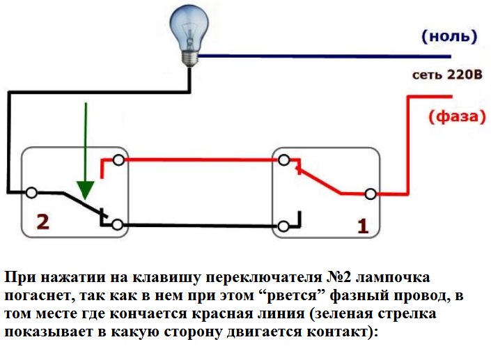
The phase from the 220 V network is connected to the input terminal of one of the pass-through switches, its output terminals are connected to the output of the second. There remains a free input terminal of the second switch, it is connected to the lighting device. The second contact of the lighting fixture is connected to the neutral wire of the network. The diagram shows that the lamp is in the off state, when the position of the contact group of any switch is changed, current is supplied to it. The next switch on one of the two switches breaks the circuit, the lamp goes out.
Closer to real conditions, the installation diagram shows a picture of the wiring of cables and wires in the junction box. By requirements of PUE(Electrical Installation Rules) in this case, a cable with three copper conductors is used:
- red - phase;
- blue - 0;
- yellow-green - ground wire.

Disconnecting cables and wires in the junction box
The circuit is divided into four sections of the circuit:
- 220 V power supply cable: with circuit breaker in the switchboard to the box;
- cable from one pass-through switch to the switch-on box;
- cable from another pass-through switch to the junction box;
- cable from lighting fixture to junction box.
Four cables are inserted into the box.
Requirements for the color of the wires for their functional purpose are fully feasible only in two sections. From the switchboard and the luminaire to the box, when the contacts of the pass-through switches are disconnected, they are partially performed. It is allowed to use wires of any color. If confused, check with a multimeter in dial mode or other measuring instrument... A phase (red) wire must be connected to the input contacts of the switches.
To control two groups of lighting, a two-key pass-through switch wiring diagram is used. If a person understands how one-key pass-through switches are connected, he will figure out how to connect a triple switch.

Wiring diagram of a two-key pass-through switch
Lighting control from 3 places
A cross-feed switch is required to control the lighting from three locations. You can install it in any place convenient for use. In the circuit, the cross switch is connected between conventional pass-through switches. They can be used on flights of stairs, to illuminate courtyards and other objects, at the request of the customer.
The cross switch is easy to make with your own hands, for this you need to slightly alter the two-key pass-through switch. Two jumpers are placed on the output contacts, and two keys are combined into one, you can simply glue one to the other. It is necessary to glue so that the mounting holes on the keys coincide with the pins on the switch. The gap between the keys can be compensated for with a cardboard spacer, to which plastic strips must be glued on both sides.
There are ready-made products in stores, you don't have to reinvent the wheel, just buy and deliver.

Lighting control circuit from 3 places
Diagrams A1 and A2 (below) show different connection options, but the functional purpose remains the same - the principle of pairing of flipping contacts is observed.

Crossover switch connection options
In cases where the lighting element is a large chandelier with two groups of bulbs or just two rows of sconces along a long corridor, two-key pass-through and cross switches should be used. The circuit is a little more complicated, but you can see that the same principle of flipping contacts works. When the light source is turned off by one of the switches, the contacts close the circuits of the other switches.
The circuit is in such a state that when any key of this group of lamps is pressed, the current flows to the contacts of the lamps. Based on these schemes, it is possible to control lighting from four or more locations by inserting additional cross switches.

Wiring diagram for four switches
Usage example
For a situation when you need to go to the house through a dark courtyard, a circuit with pass-through switches in two places is ideal. In a private house, it is easy to implement this project with your own hands. In the hallway next to the switchboard, you need to install a junction box and one pass-through switch. The second - must be placed on the inside on the fence near the wicket; lamp posts installed along the path can be used as lighting devices. In large electrical stores, there are many options with original decorative finishes.
The connection should be made as described above. It is recommended to lay the cables from the outdoor switch and between the poles in plastic pipes underground. It is not necessary to bury deeply, 30-40 cm will be enough to protect against mechanical damage. It makes no sense to take into account the depth of freezing in each region, this is not a water supply system, copper wires will not freeze through.
How to connect. Video
How to connect a pass-through switch according to all the rules can be found in this video.
Having studied the principles of operation of the circuit with two one-button switches and having assembled it with your own hands, you can without outside help start the installation of more complex circuits with two-button switches in three places or three-button switches in two places, if necessary.
When designing lighting, you need to know about the basic circuitry for connecting switches. The circuit breaker wiring diagram directly depends on the tasks that face a particular switch, i.e. control of one or another lamp or a group of lamps.
1 Wiring diagram for one-button switch:

The simplest single luminaire is connected according to this scheme. The switch contact switches the phase. Most of the luminaires in our homes and offices are connected this way.
The light switch must always break the phase conductor!

This scheme is used to turn on (off) luminaires in large rooms or single multi-lamp luminaires. All luminaires or lamps are divided into two groups. Each key is used to control a separate group.

The application of this circuit is similar to a two-button switch. All lamps are divided into three groups.

In long rooms with two exits, i.e. in walk-through rooms, it is advisable to install walk-through switches - switches for control from two places. These switches have a special contact group and one button. Recently, these were used in the corridor during the reconstruction of a private house.

Apparently, this scheme should be used for long corridors. At the beginning and at the end of the room, near the exits, ordinary single-key switches with circuit 6 are installed, and in the middle of the corridor there is a two-key switch with circuit (6 + 6). The scheme works as follows: entered the room - turned on the light of only the first half of the lamps, reached the middle - turned on the second half of the lamps with one key, turned off the first half of the lamps with the second switch key, reached the end of the corridor - turned off the second part of the lamps.

The difference from the previous circuit is that a single-button switch with a 6/2 circuit is used in the center. Here, when this switch is pressed, some lamps are turned off, and the second are turned on.
7 Control scheme for a luminaire or a group of luminaires from four places using switches with schemes 6 and 6/2:

Control circuit of a luminaire or a group of luminaires from four places using switches with schemes 6 and 6/2
I use this scheme in branched corridors with three or four exits. The cutouts are fitted with circuit breakers 6, and in the center with circuit 6/2.
It is worth noting that these diagrams do not show a protective grounding conductor - PE, which must be mandatory, although in household chandeliers, there is often nowhere to connect it. Well, you need to remember about the distribution (terminal) boxes.
Output: the most common circuit breakers:
- one-button switch;
- two-button switch;
- three-button switch;
- pass-through one-key switch with circuit 6;
- pass-through one-key switch with a 6/2 circuit.
- two-key pass-through switch with a diagram (6-6);
3 options for lighting control (6 lamps) using a two-button switch:

Prices for housing and communal services are increasing annually, which makes us think about saving, including electricity. Moreover, this applies to those places that a person did not even think about before. For example, lighting staircases and landings in multi-storey buildings. In the recent past, when electricity prices were paltry, staircases were lit 24 hours a day. This problem is also relevant in private houses with more than one floor connected by a staircase. To save money, you have to turn off the light, but for this you need to either go down the stairs or climb it again. This is extremely inconvenient, so sometimes it is simply not turned off and it burns until the morning, when it is not daylight.
For the convenience of lighting in such areas, the so-called "pass-through" switches have been developed. They are also called "duplicate" or "flip". They can be distinguished from classic switches by the presence of a larger number of contacts. Therefore, in order to connect them, you need to know the circuit, and even more so, to be able to understand the principle of their operation. Naturally, this is not entirely simple, but absolutely real.
On the key of the pass-through switch there are two arrows (not large) directed up and down.
 This is the form of a single-key pass-through switch. There may be double arrows on the key.
 The wiring diagram is not much more complicated than the wiring diagram of a classic switch. The only difference is in a larger number of contacts: a conventional switch has two contacts, and a straight-through switch has three contacts. Two out of three contacts are considered shared. In the lighting switching circuit, two or more similar switches are involved.
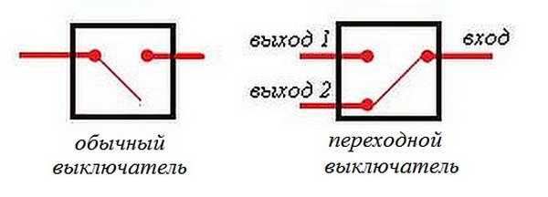 Differences - in the number of contacts
 The switch works as follows: when switching with the key, the input is connected to one of the outputs. In other words, the pass-through switch is designed for two operating states:
- The input is connected to output 1;
- The input is connected to output 2.
He has no intermediate positions, therefore, the circuit works as it should. Since there is a simple connection of contacts, in the opinion of many experts they should have been called "switches". Therefore, the transfer switch can be safely attributed to such devices.
In order not to be mistaken what kind of switch is, you should familiarize yourself with the switching circuit, which is present on the switch body. Basically, the circuit is available on branded products, but you will not see it on inexpensive, primitive models. Typically, the circuit can be found on circuit breakers from Lezard, Legrand, Viko, etc. As for cheap Chinese switches, basically, there is no such circuit, so you have to call the ends with the device.
As mentioned above, in the absence of a circuit, it is better to call contacts at different key positions. This is also necessary in order not to confuse the ends, since irresponsible manufacturers often confuse terminals during the production process, which means that it will not work correctly.
To ring the contacts, you must have either a digital or a dial gauge. The digital device should be switched to the dialing mode with the switch. In this mode, short-circuited sections of electrical wiring or other radio components are determined. When the ends of the probes are closed, the device emits sound signal, which is very convenient, since there is no need to look at the display of the device. If there is a dial gauge, then when the ends of the probes are closed, the arrow deviates from it to the right until it stops.
In this case, it is important to find a common wire. For those who have the skills to work with the device, there will be no special problems, but for those who picked up the device for the first time, the task may not be solvable, despite the fact that you need to understand only three contacts. In this case, it is better to first watch the video, which clearly explains, and most importantly shows how to do it.
Wiring diagram for two pass-through switches
Such a scheme can be of significant assistance in organizing lighting on the stairs (in a two-story house), in a long corridor or in a walk-through room. It can be quite convenient to organize lighting in the bedroom, when one switch is installed at the entrance to the bedroom, and the other next to the bed. In this case, you do not have to constantly get out of bed to turn off the main light.
 Electrical diagram connection of two pass-through switches
 The wiring diagram is very simple and straightforward: a phase is applied to the input of one of the switches, the input of the other switch is connected to one of the wires of the chandelier (lamp). The other end of the luminaire is connected directly to the neutral wire. The N1 outputs of both switches are wired together like the N2 outputs.
The circuit works quite simply. If you look at the diagram, then in this position the light source is on. With the subsequent switching of any of the switches, in random order, the lamp will then turn off, then turn on.
In order to make it more clear, you should carefully look at the picture.
 Wiring between two pass-through switches.
 In the case of installing such switches indoors, the wiring should be done as shown in the figure below. Modern requirements allow wiring at a distance of 15 cm from the ceiling. As a rule, the wires are laid in special trays or boxes, and the ends of the wires are concentrated in junction (junction) boxes. This approach has undeniable advantages. The main thing is that a damaged wire can always be replaced. The connection of wires in junction boxes is carried out using special clamps (terminal blocks). At the same time, twists are also allowed, which are then necessarily soldered and reliably isolated.
The output of the second switch is connected to one of the conductors of the lighting going to the lamp. The white wires are the wires connecting the outputs of both switches.
 Wiring in a residential area
 How the ends of the wires are connected in the junction box can be found out by watching the corresponding video.
Three-point lighting control option
If there is a need for remote control of the luminaire from three places, then you will also have to purchase a cross switch. It switches simultaneously not one, but two contacts at a time, so it has two inputs and two outputs.
How to connect all three switches can be seen in the figure. This is somewhat more complicated than the previous case, but you can understand how it works.
 Electrical circuit for switching on a lamp from three places.
 To connect an electric light source, according to this diagram, you must perform the following operations:
- The neutral wire is connected to one of the lamp wires.
- The phase wire is connected to the input contact of one of the feed-through switches.
- The free lamp wire is connected to the input contact of the second switch (through).
- The two output contacts of the pass-through switch are connected to the two input contacts of the cross-circuit breaker.
- The two output contacts of the second pass switch are connected to the two output contacts of the cross switch.
The scheme is the same, but it is shown more clearly where exactly to connect the wires.
 What terminals are the wires connected to?
 This is approximately how the wires should be routed around the room.

Based on the three-point control scheme, it is possible to assemble 4-point or 5-point schemes. In such cases, it is necessary to increase the number of cross switches. They should always be installed between two pass-through switches.
 5-point lamp on / off organization diagram.
 If you remove one of the cross switches from this scheme, you get a 4-point option, and if you add one cross switch to it, then the 6-point option will already come out.
Two-key pass-through switch: wiring diagram
In order to control the operation of two lamps from several points, there are two-key pass-through switches. They have six contacts. The main thing is to define common contacts. They are determined according to the same principle as when searching for a common contact in single-key pass-through switches.
In a circuit that uses two two-key pass-through switches, significantly more wires are used.
The phase wire is fed to the inputs of both switches, and the other inputs of the switches are connected to one of the ends of one and the other lamp. The free ends of the lamp are connected to the neutral conductor. Two outputs of one switch are connected to two outputs of the second switch, and the other two outputs of this switch are connected to the other two outputs of the first switch.
), however, such switches have one serious drawback - lighting control, i.e. it can be turned on and off only from one place. Imagine a situation that everyone faced, for example: you go home, turn on the light in the hallway, take off your outerwear and walk into the room, but stop, the light in the hallway needs to be turned off, and having done this, you will have to leave the hallway in the dark, the same applies to long ones. corridors or flights of stairs. In such situations, it becomes necessary to control the lighting from two places, it is for the solution of such tasks that the so-called pass-through switches are intended.
In this article, we will consider various options for connecting pass-through switches to control lighting from 2, 3 or more places.
NOTE: Before connecting the pass-through switch, it is necessary to check the diagram shown in his passport and / or the diagram printed on the back of the switch itself (if any).
2. Lighting control from two places:
To organize lighting control from two places, it is necessary to use 2 pass-through switches. Below are the connection diagrams for two single-key (single) and two two-key (double) pass-through switches.
2.1 Connection of two pass-through one-button switches.
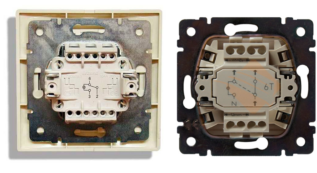
To begin with, let's figure out what a single-key pass-through switch is, outwardly it is practically indistinguishable from a conventional one-key switch, however, unlike the latter, it has not 2, but 3 terminals for connecting wires, in addition, two triangles located vertically, one can be present on the pass-through switch key above the other and pointing their vertices up and down, respectively:
As you can see in the picture above, on the reverse side of the pass-through switch, as a rule, there is its circuit, while the terminals for connecting the wires to the switch can have different alphabetic, digital or symbolic designations, for example, it can be: "L, 1,2"; or "1,2,3"; also, the designations can be arrow, in this case one arrow points to the inside of the switch, and the other two arrows point to the outside.
One-key pass-through switches are connected with three-core cables (as shown in the picture above), for example, with a VVG 3x1.5 cable - if the internal wiring is made of copper, or with an AVVG 3x2.5 cable - if the internal wiring is made of aluminum.
Pass-through switch connection diagram:
The connection of wires to single-key pass-through switches is performed as follows:
By connecting 2 pass-through switches in this way, you can organize lighting control from two places. How exactly such a scheme works can be seen in the GIF animation below:
As you can see in this diagram, unlike conventional switches that simply break (turn off) the electrical circuit (see article :), pass-through switches switch from one circuit to another, therefore, often pass-through switches are called pass-through switches.
2.2 Connection of two two-key pass-through switches.
A double pass-through switch consists of two single-key pass-through switches combined in one housing, respectively, such a switch will have 6 terminals for connecting wires, therefore, the connection of the pass-through two-key switch must be done with two three-core cables.
Wiring diagram of a two-key 2-point pass-through switch:
Connect the wires to the double pass switches as follows:
3. Lighting control from three or more locations
If it is necessary to connect pass-through switches to control lighting from 3 places or more, as a third, fourth, etc. switches must be connected cross or, as they are called, intermediate switches (switches), they got this name because these switches must be included in the circuit between two pass-through switches.
One-button cross switches have 4 terminals for connecting wires, two-button switches, respectively, have 8 terminals, etc. On the keys of intermediate switches, as well as on the passage switches, two triangles can be applied, however, unlike the passage switches, they are not vertically located relative to each other, but horizontally:
The cross switch is connected according to one of the following diagrams.
The connection diagram for 3-pass switches (2-pass and one cross) for lighting control from three places will look like this:
In turn, the connection of wires to the switches with such a scheme will be performed as follows (note: before connecting, you must check the diagram located on the back of the switch or given in its passport):
This connection diagram of the pass-through switches, together with the cross, allows you to organize lighting control from three places. The principle of operation of such a scheme can be studied by the GIF animation below: