Thermoregulators are widely used in modern household appliances, cars, heating and air conditioning systems, in manufacturing, in refrigeration equipment and during the operation of ovens. The principle of operation of any thermostat is based on turning on or off various devices after reaching certain temperature values.
Modern digital thermostats are controlled using buttons: touch or conventional. Many models are also equipped with a digital panel that displays the set temperature. The group of programmable thermostats is the most expensive. With the help of the device, you can envisage a change in temperature by the hour or set required mode a week ahead. The device can be controlled remotely: via a smartphone or computer.
For a complex technological process, for example, a steel-making furnace, making a thermostat with your own hands is a rather difficult task that requires serious knowledge. But collect small device for a cooler or incubator, any home craftsman can do it.
In order to understand how the temperature regulator works, consider a simple device that is used to open and close the damper of a mine boiler and is triggered when the air heats up.
For the operation of the device, 2 aluminum pipes, 2 levers, a return spring, a chain that goes to the boiler, and an adjusting unit in the form of a crane-axle box were used. All components were installed on the boiler.
As you know, the coefficient of linear thermal expansion of aluminum is 22x10-6 0С. When heating an aluminum pipe one and a half meters long, 0.02 m wide and 0.01 m thick to 130 degrees Celsius, an elongation of 4.29 mm occurs. When heated, the pipes expand, due to this, the levers are displaced, and the damper closes. As the pipes cool down, they decrease in length, and the levers open the damper. The main problem when using this circuit is that it is very difficult to accurately determine the response threshold of the thermostat. Today, preference is given to devices based on electronic components.

The scheme of work of a simple thermostat
Typically, relay-based circuits are used to maintain the set temperature. The main elements included in this equipment are:
- temperature sensor;
- threshold scheme;
- executive or indicator device.
Semiconductor elements, thermistors, resistance thermometers, thermocouples and bimetallic thermostats can be used as a sensor.
The thermostat circuit reacts to the excess of the parameter over the set level and turns on the executive device. The simplest version of such a device is a bipolar transistor element. The thermal relay is based on the Schmidt trigger. A thermistor acts as a temperature sensor - an element whose resistance changes depending on an increase or decrease in degrees.
R1 is a potentiometer that sets the initial offset on thermistor R2 and potentiometer R3. Due to the adjustment, the actuator is triggered and relay K1 is switched when the resistance of the thermistor changes. In this case, the operating voltage of the relay must correspond to the operating power supply of the equipment. To protect the output transistor from voltage surges, a semiconductor diode is connected in parallel. The load value of the connected element depends on the maximum current of the electromagnetic relay.

Attention! On the Internet, you can see pictures with drawings of a thermostat for various equipment. But quite often the picture and description do not match. Sometimes the pictures may simply represent other devices. Therefore, production can be started only after careful study of all the information.
Before starting work, you should decide on the power of the future thermostat and the temperature range in which it will work. The refrigerator will require some elements, and the heating will require others.
Thermostat on three elements
One of the elementary devices, by the example of which you can assemble and understand the principle of operation, is a simple do-it-yourself thermostat designed for a fan in a PC. All work is done on a breadboard. If there are problems with the pallet, then you can take a solderless board.
The thermostat circuit in this case consists of only three elements:
- power transistor MOSFET (N channel), you can use IRFZ24N MOSFET 12V and 10A or IFR510 Power MOSFET;
- potentiometer 10 kOhm;
- NTC thermistor 10 kOhm, which will act as a temperature sensor.
The temperature sensor reacts to an increase in degrees, due to which the whole circuit is triggered, and the fan turns on.
Now let's move on to setting up. To do this, turn on the computer and adjust the potentiometer, setting the value for the off fan. At the moment when the temperature approaches the critical one, we reduce the resistance as much as possible before the blades rotate very slowly. It is better to make the adjustment several times to make sure that the equipment is working efficiently.

The modern electronic industry offers elements and microcircuits that differ significantly in appearance and technical specifications... Each resistance or relay has several analogs. It is not necessary to use only those elements that are indicated in the diagram, you can take others that match the parameters with the samples.
Thermostats for heating boilers
When adjusting heating systems, it is important to accurately calibrate the device. This will require a voltage and current meter. To create a working system, you can use the following diagram.

Using this scheme, you can create outdoor equipment for controlling a solid fuel boiler. The role of the zener diode is performed by the K561LA7 microcircuit. The operation of the device is based on the ability of the thermistor to reduce resistance when heated. The resistor is connected to the electricity voltage divider network. The required temperature can be set using the variable resistor R2. The voltage is supplied to the 2I-NOT inverter. The resulting current is fed to the capacitor C1. A capacitor is connected to 2I-NOT, which controls the operation of one trigger. The latter is connected to the second trigger.
Temperature control goes according to the following scheme:
- with a decrease in degrees, the voltage in the relay increases;
- when a certain value is reached, the fan, which is connected to the relay, turns off.
It is better to solder on a mole rat. As a battery, you can take any device operating within 3-15 V.
Carefully! Installation homemade appliances any purpose for heating systems can lead to equipment failure. Moreover, the use of such devices may be prohibited at the level of services that supply communications in your home.
Digital thermostat
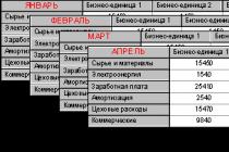
In order to create a fully functioning thermostat with accurate calibration, you cannot do without digital elements. Consider a device for controlling temperatures in a small vegetable store.
The main element here is the PIC16F628A microcontroller. This microcircuit provides control of various electronic devices. The PIC16F628A microcontroller contains 2 analog comparators, an internal oscillator, 3 timers, CCP comparison modules and USART data exchange.
When the thermostat is operating, the value of the existing and set temperature is fed to the MT30361 - a three-digit indicator with a common cathode. In order to set the required temperature, use the buttons: SB1 - to decrease and SB2 - to increase. If you carry out the setting while pressing the SB3 button, you can set the hysteresis values. The minimum hysteresis value for this circuit is 1 degree. A detailed drawing can be seen on the plan.

When creating any of the devices, it is important not only to properly solder the circuit itself, but also to think about how best to place the equipment. It is necessary that the board itself be protected from moisture and dust, otherwise a short circuit and failure of individual elements cannot be avoided. Also, care should be taken to isolate all contacts.
Video
To maintain the required temperature range in a modern refrigerator, a special thermostat device, abbreviated as a thermostat, is used. The refrigerator thermostat switches the compressor on and off. Sometimes a situation arises when it fails, and there is nothing to replace it with, then you can find the right solution and make it yourself, consider the diagram of such a device.
The thermostat has a galvanic isolation from the supply voltage and allows maintaining the temperature inside the refrigerator chamber with sufficient accuracy.

Refrigerator thermostat on OS TLC271
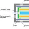
The temperature sensor is LM335. In fact, as follows from the description, this is a voltage regulator whose parameters are sensitive to temperature changes. LM335 is connected with only two contacts. The cathode is connected to positive through the load resistor R1, and the anode to negative.
The voltage from the LM335 goes to the direct input of the TLC271 comparator, at its inverse input there is a potential from the voltage divider across the resistances R3, R4, R5.
The temperature range in the inner chamber of the refrigerator is regulated by a variable resistance R4. If the temperature rises above this range, then the voltage at the direct input of the comparator will decrease compared to the inverse input. This will create a logic-one signal at the output of the comparator, which will turn on the transistor.
In the collector circuit of the KT3102 transistor, two opto-thyristors are connected. Their LED parts are connected in series, and their thyristor components are parallel and counter-directed. Therefore, it appears interesting opportunity control an alternating current (the first thyristor of the optocoupler works on the first half-wave, and the second on the second half-wave. The compressor of the refrigerator turns on.
As soon as the temperature inside the refrigerator chamber drops below the set range, a logical zero level is formed at the comparator output and the compressor turns off.
With this variant of the circuit, the compressor turns on when the temperature reaches + 6 degrees and turns off when it drops to + 4 degrees Celsius.
This temperature range is quite enough to maintain the required storage temperature of food, and at the same time, the comfortable operation of the compressor is ensured, preventing its severe wear. This is especially true in older models, using a thermal relay to start the engine.

Refrigerator thermostat on LM35
The thermostat reads the temperature with an LM35 sensor, the resistance of which changes depending on the temperature in the refrigerator compartment, linearly calibrated with a factor of 10 mV per 1 degree Celsius.
Since the output voltage is clearly not enough to open VT1, the LM35 sensor is switched on according to the current source circuit. Its output is loaded with resistance R1 and therefore the current strength changes in proportion to the temperature in the chamber. This current causes a drop across the resistance R2. The voltage drop controls the operation of the first bipolar transistor VT1. If the voltage drop is higher than the threshold voltage level of the emitter junction, both transistors open, relay K1 is triggered, and its front contacts start the electric motor.
Resistance R3 creates a positive feedback loop. This provides hysteresis to prevent starting the compressor too often. The winding of the electromagnetic relay must be five volts, and its contacts must withstand the current and voltage flowing through them, see.
The LM35 temperature sensor is located in the correct location inside the refrigeration unit. The resistance of the resistor R1 is soldered directly to the sensor so that you can connect the LM35 to the board with just two wires.
If you need to slightly adjust the temperature level, then this can be done by selecting the value of the resistances of the resistors R1 or R2. Resistor R3 sets the hysteresis value.
The design is based on an operational amplifier K157UD1 with an output current of 300mA, which makes it possible to connect an optothyristor directly to the output of the op-amp without using a buffer transistor. The op-amp is included as a comparator. The cut-off temperature of the refrigerator compressor is set by the resistance R1. The difference between the switch-on and switch-off temperatures is set by the resistance R4.

Instead of an electronic key on an optosimistor and a powerful triac VS1, you can use a conventional relay with a switching current of 10 Amperes. In this case, the relay coil is connected to the sixth pin of the DA1 chip and the third pin of DA2. A damping diode is also connected to the same terminals. In the case of using a relay, it will be necessary to increase the capacity of the capacitor C5 to 1 microfarad. If the design will use electronic key, then the diodes VD1 and VD2 can be eliminated by connecting the second output of DA2 directly to the case.

After all, no one can forbid us to use one of them for a possible replacement.
Fig. 1
The generator on the DD1 chip in Fig. 1 has two independent timing circuits, respectively R1, R3, C1; and R2, R3, C2; which are switched by keys on the DD2 chip. The keys are controlled by pulses from the output of the fifteenth digit of the DD1 divider. At a high level at pin 5 of DD1, resistors R2, R4 and capacitor C2 are connected to the internal logic elements of the K176IE5 microcircuit through the keys DD2.1 and DD2.4. At a low level at pin 5 of the K176IE5 microcircuit, resistors R1, R3 and capacitor C1 are connected to pins 11 and 12 of DD1 through keys DD2.3 and DD2.2, respectively. Thus, if the parameters of the timing circuits are different, then the pulse duration will differ from the falloff duration. It turns out an RC generator with adjustable parameters. The frequency of the RC-generator can be approximately determined by the formula F = 0.7 / RC. At pin 5 of DD1, the generator frequency is divided by 32768. The adjustment range can be set within a wide range from tenths of a second to many hours. So, for example, at R = 3.3 mOhm, C = 1μF T = 455 hours (F = 0.2Hz).
When calculating the duration, it must be remembered that the operating or pause time of the refrigerator will be half the calculated one, since only a part of the period is taken from output 15, or high level, or low. Resistors R1 and R2 are required to set the minimum values for operation and pause of the refrigerator. Elements R2, R4, C2 determine the operating time of the refrigerator (relay contacts K1 are closed), and elements R1, R3, C1 - the duration of the pause.
It is practically determined that an adjustment range of 5 to 30 minutes is sufficient. For such a range, it is necessary to take the following values of timing circuits: R1 = R2 = 43k, R3 = R4 = 470k, C1 = C2 = 0.15mk. For large adjustment ranges, the values of variable resistors can be increased to 1mOhm.
When a unit appears on the 14th bit of the counter (state 01), the RC-generator works with the included pause timing elements - R1, R3, C1. The next state of the counter is 10. The 15-bit unit includes timing elements of work - R2, C2 and resistors R1, R3, R4 are connected in parallel to R2. The generator operates at a different frequency and therefore the time interval t1 is not equal to the time interval t2. When the counter is 11, timing elements and pauses and work are switched on in parallel. Moreover, if, when connected in parallel, the capacities C1, C2 are summed up, then the values of the resistors are calculated according to the well-known formula and will always be less than the smaller value of the resistors connected in parallel (with the ratings indicated on the diagram, the difference between the maximum and minimum influence on the resistance of the work circuit will be 1 kOhm). The time interval t3 will differ from the interval t2, but their sum will be the operating time of the refrigerator. State 00 is interesting in that the values of the capacitances C1, C2 are not only summed up with each other, but also with small values of the capacitances of the transitions public keys in series connection. That is, the total capacity of the timing chain will be very small. Even with a large resistor R1 + R3 + R4 connected to the RC circuit, the generator frequency will be large, and the time interval t4 will be fractions of a second (maximum 0.8 seconds, minimum 0.2 seconds). The time t4 is added to the time t1 and is the pause time.
The operating time, at the ratings indicated on the diagram, is 20-23 minutes. The pause time varies from 3 to 30 minutes. It is practically determined that any mode of the refrigerator can be set by changing only the pause duration.
If you need other intervals of time of work and pauses, then you need to be guided by simple rule... To reduce the influence of timing circuits on the calculated frequency when they are connected together, it is necessary to increase the capacitance rating in the RC circuit connected to the most significant bit of the meter. And in an RC circuit connected to the least significant bit of the counter, it is necessary to increase the resistor values.
The unit from the output of the 15th bit of the counter through the resistor R5 and the switch on the transistor VT1 turns on the intermediate relay K1. The intermediate relay was chosen to reduce the size of the power supply. Used relay type RES6 passport RFO.452.145. A more powerful 220 V relay can be anything with contacts that can withstand a switching current of at least 10 A.
Resistors MLT-0.125, R3 -SPO-0.5. Capacitors: C1 - KM5B, C2 - K73-17. Chip K561KT3 can be replaced without change printed circuit board on K176KT1. Relay K1 and filter capacitor C3 are located together with the power supply.
Literature.
Biryukov S.A. Digital devices on MOS - integrated circuits. - M., Radio and communication, 1990
Bannikov V.V., Radio 8.1994
In this article, we will consider devices that maintain a certain thermal regime, or signal that the desired temperature has been reached. Such devices have a very wide range of applications: they can maintain a given temperature in incubators and aquariums, warm floors, and even be part of a smart home. For you, we have provided instructions on how to make a thermostat with your own hands and at a minimum cost.
A bit of theory
The simplest measuring sensors, including those that respond to temperature, consist of a measuring half-arm of two resistances, a reference one and an element that changes its resistance depending on the temperature applied to it. This is shown more clearly in the picture below.
As can be seen from the diagram, resistor R2 is a measuring element of a homemade thermostat, and R1, R3 and R4 are the reference arm of the device. This is a thermistor. It is a conductive device that changes its resistance when the temperature changes.
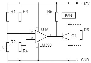
An element of the thermostat that responds to a change in the state of the measuring arm is an integrated amplifier in the comparator mode. This mode jumps the output of the microcircuit from the off state to the working position. Thus, at the output of the comparator, we have only two values "on" and "off". The load of the microcircuit is a PC fan. When the temperature reaches a certain value in the legs of R1 and R2, a voltage shift occurs, the input of the microcircuit compares the value at pin 2 and 3, and the comparator switches. The fan cools the necessary object, its temperature drops, the resistance of the resistor changes, and the comparator turns off the fan. Thus, the temperature is maintained at a predetermined level, and the operation of the fan is controlled.
Schematic overview
The voltage of the difference from the measuring arm is fed to a paired transistor with a high gain, and an electromagnetic relay acts as a comparator. When the coil reaches a voltage sufficient to pull in the core, it is triggered and connected through its contacts of the actuators. When the set temperature is reached, the signal on the transistors decreases, the voltage on the relay coil simultaneously drops, and at some point the contacts are disconnected and the payload is disconnected.

A feature of this type of relay is the presence - this is a difference of several degrees between turning on and off a homemade thermostat, due to the presence of an electromechanical relay in the circuit. Thus, the temperature will always fluctuate by several degrees around the desired value. The assembly option provided below is virtually devoid of hysteresis.
Principled electronic circuit analog thermostat for incubator:

This scheme was very popular for repetition in 2000, but even now it has not lost its relevance and copes with the function assigned to it. If you have access to old parts, you can assemble a thermostat with your own hands almost free of charge.
The heart of the homemade product is the K140UD7 or K140UD8 integrated amplifier. In this case, it is connected with a positive feedback and is a comparator. Thermosensitive element R5 is an MMT-4 type resistor with negative TKE, which means that when heated, its resistance decreases.
The remote sensor is connected via a shielded wire. To reduce and false triggering of the device, the length of the wire should not exceed 1 meter. The load is controlled through the VS1 thyristor and the maximum allowable power of the connected heater depends on its rating. In this case, 150 watts, the electronic thyristor key must be installed on a small radiator to remove heat. The table below shows the ratings of radioelements for assembling a thermostat at home.

The device does not have a galvanic isolation from the 220 Volt network, be careful when setting up, there is a mains voltage on the regulator elements, which is life-threatening. After assembly, be sure to insulate all contacts and place the device in a non-conductive housing. The video below shows how to assemble a transistor thermostat:
Homemade transistor thermostat
Now we will tell you how to make a temperature controller for a warm floor. Working scheme copied from a serial sample. Useful for those who want to review and repeat, or as a sample for troubleshooting a device.
The center of the circuit is the stabilizer microcircuit connected in an unusual way, LM431 starts to pass current above 2.5 volts. It is this value that this microcircuit has an internal reference voltage source. At a lower current value, it does not pass anything. This feature began to be used in all kinds of thermostat circuits.

As you can see, the classic circuit with a measuring arm remains: R5, R4 are additional resistors, and R9 is a thermistor. When the temperature changes, the voltage at the input 1 of the microcircuit shifts, and if it reaches the operating threshold, then the voltage goes further along the circuit. In this design, the load for the TL431 microcircuit is the HL2 operation indication LED and the U1 optocoupler, for optical isolation of the power circuit from the control circuits.
As in the previous version, the device does not have a transformer, but is powered by a quenching capacitor circuit C1, R1 and R2, so it is also under a life-threatening voltage, and you need to be extremely careful when working with the circuit. To stabilize the voltage and smooth out the ripple of network surges, a Zener diode VD2 and a capacitor C3 are installed in the circuit. The HL1 LED is installed on the device for visual indication of voltage presence. The power control element is a VT136 triac with a small strapping for control through an optocoupler U1.
With these ratings, the control range is within 30-50 ° C. Despite the seeming complexity of the design, it is easy to set up and easy to repeat. An illustrative diagram of a thermostat on a TL431 microcircuit, with external power supply 12 volts for use in home automation systems is shown below:

This thermostat is capable of controlling a computer fan, power relay, indicator lights, and audible alarms. To control the temperature of the soldering iron, there is an interesting circuit using the same TL431 integrated circuit.

To measure the temperature of the heating element, a bimetallic thermocouple is used, which can be borrowed from a remote meter in a multimeter or bought in a specialized radio parts store. To increase the voltage from the thermocouple to the TL431 trigger level, an additional amplifier is installed on the LM351. The control is carried out through the MOC3021 optocoupler and the T1 triac.
When the thermostat is connected to the network, the polarity must be observed, the minus of the regulator must be on the neutral wire, otherwise the phase voltage will appear on the body of the soldering iron, through the thermocouple wires. This is the main drawback of this circuit, because not everyone wants to constantly check that the plug is connected to the outlet, and if you neglect this, you can get an electric shock or damage electronic components during soldering. The range is adjusted by resistor R3. This scheme will provide long work soldering iron, eliminate its overheating and increase the quality of soldering due to the stability of the temperature regime.
Another idea for assembling a simple thermostat is discussed in the video:
Temperature regulator on the TL431 chip
A simple regulator for a soldering iron
The disassembled examples of temperature controllers are quite enough to meet the needs of a home craftsman. The schemes do not contain scarce and expensive spare parts, are easy to repeat and practically do not need to be set up. These homemade products can easily be adapted to regulate the temperature of the water in the water heater tank, monitor the heat in an incubator or greenhouse, upgrade an iron or a soldering iron. In addition, you can restore an old refrigerator by altering the regulator to work with negative temperatures, by replacing the resistances in the measuring arm. We hope our article was interesting, you found it useful for yourself and understood how to make a thermostat with your own hands at home! If you still have questions, feel free to ask them in the comments.
Here is a thermostat design for a refrigerator that has been in operation for over 2 years. And it all started with the fact that after returning from work and opening the refrigerator, he found it warm. Turning the thermostat knob did not help - the cold did not appear. Therefore, I decided not to buy a new unit, which is also rare, but to make an electronic thermostat on ATtiny85 myself. With the original thermostat, the difference is that the temperature sensor is on the shelf and not hidden in the wall. In addition, 2 LEDs have appeared - they signal that the unit is turned on or the temperature is above the upper threshold.
Refrigerator thermostat diagram on MK
Photo of the original thermostat and homemade


To connect, it was required to conduct a second 220 V wire (taken from the lighting lamp) to power the transformer.
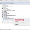
The connector to which the potentiometer is connected is also the ISP programming connector.

The board is protected from moisture with a special varnish for printed circuit boards.

The thermostat currently works without problems, and most importantly, it cost about 10 times less than the original one.

The transformer here is 6 V. It was chosen such as to minimize losses on the 7805 microcircuit.

The relay here can be put on 12 V. If you take the voltage to it before the stabilizer. To reduce costs, it would be possible to create a transformerless power supply, although there are supporters and opponents of such a solution (electrical safety). Another cost cut is the elimination of the AVR microcontroller. There are Dallas thermometers that can also work in thermostat mode.