Most audio enthusiasts are quite categorical and not ready for compromises when choosing equipment, rightly believing that the perceived sound must be clear, strong and impressive. How to achieve this?
Data search for your request:
Amplifier on tda8571j printed circuit board
Schemes, reference books, datasheets:
Price lists, prices:
Discussions, articles, manuals:
Wait until the end of the search in all databases.
Upon completion, a link will appear to access the found materials.
Perhaps the main role in resolving this issue will be played by the choice of amplifier.
Function
The amplifier is responsible for the quality and power of sound reproduction. At the same time, when buying, you should pay attention to the following designations, which mark the introduction of high technologies in the production of audio equipment:
- Hi fi. Provides maximum purity and accuracy of sound, freeing it from extraneous noise and distortion.
- Hi end. The choice of a perfectionist who is ready to pay a lot for the pleasure of distinguishing the smallest nuances of his favorite musical compositions. Often hand-assembled equipment falls into this category.
Specifications to pay attention to:
- input and output power. The nominal value of the output power is decisive, since edge values are often unreliable.
- Frequency range. Varies from 20 to 20000 Hz.
- The coefficient of non-linear distortion. It's simple - the smaller the better. The ideal value, according to experts, is 0.1%.
- Signal-to-noise ratio. Modern technology assumes a value of this indicator in excess of 100 dB, which minimizes extraneous noise when listening.
- dumping factor. Reflects the output impedance of the amplifier in relation to the nominal load impedance. In other words, a sufficient damping factor (more than 100) reduces the occurrence of unnecessary vibrations in equipment, etc.
It should be remembered: the manufacture of high-quality amplifiers is a laborious and high-tech process, therefore, a too low price with decent characteristics should alert you.
Classification
To understand all the variety of market offers, it is necessary to distinguish the product according to various criteria. Amplifiers can be classified:
- By power. Preliminary - a kind of intermediate link between the sound source and the final power amplifier. The power amplifier, in turn, is responsible for the strength and volume of the signal at the output. Together they form a complete amplifier.
Important: the primary conversion and signal processing takes place precisely in the preamplifiers.
- According to the element base, tube, transistor and integrated PAs are distinguished. The latter arose in order to combine the advantages and minimize the disadvantages of the first two, for example, the sound quality of tube amplifiers and the compactness of transistor ones.
- According to the mode of operation, amplifiers are divided into classes. The main classes are A, B, AB. If class A amplifiers use a lot of power, but produce high quality sound, class B is exactly the opposite, class AB seems to be the best choice, representing a compromise between signal quality and sufficiently high efficiency. There are also classes C, D, H and G, which have arisen with the use of digital technologies. There are also single-cycle and push-pull modes of operation of the output stage.
- By the number of channels, amplifiers can be one-, two- and multi-channel. The latter are actively used in home theaters to form the volume and realism of the sound. Most often there are two-channel, respectively, for the right and left audio systems.
Attention: the study of the technical components of the purchase, of course, is necessary, but often the decisive factor is the elementary listening to the equipment according to the principle of sounds or does not sound.
Application
The choice of amplifier is more justified by the purposes for which it is purchased. We list the main areas of use of audio frequency amplifiers:
- As part of a home audio system. Obviously, the best choice is a tube two-channel single-cycle in class A, also the best choice can be a three-channel class AB, where one channel is defined for a subwoofer, with Hi-fi function.
- For car audio system. The most popular four-channel amplifiers are AB or D class, in accordance with the financial capabilities of the buyer. In cars, the crossover function is also in demand for smooth frequency control, which allows you to cut frequencies in the high or low range as needed.
- in concert equipment. Higher demands are reasonably placed on the quality and capabilities of professional equipment due to the large space for the propagation of sound signals, as well as the high need for intensity and duration of use. Thus, it is recommended to purchase an amplifier with a class not lower than D, capable of operating almost at the limit of its power (70-80% of the declared one), preferably in a case made of high-tech materials that protects against negative weather conditions and mechanical influences.
- in studio equipment. All of the above is true for studio equipment. You can add about the largest frequency reproduction range - from 10 Hz to 100 kHz in comparison with that from 20 Hz to 20 kHz in a domestic amplifier. Also noteworthy is the possibility of separate volume control on different channels.
Thus, in order to enjoy clear and high-quality sound for a long time, it is advisable to study all the variety of offers in advance and choose the option of audio equipment that best suits your needs.
Not supplied due to the removal of the microcircuit from production
The model has been withdrawn from sale.
BM2043.
Not available
To report
on arrival at the warehouse
To favoritesThe model has been withdrawn from sale.
See upgraded replacement BM2043.
The proposed kit will allow a radio amateur to assemble a simple and reliable car bass amplifier with a minimum coefficient of non-linear distortion and a level of intrinsic noise. Its main purpose is to install it in your car radio, instead of the old bass amplifier, to increase its output power. Thanks to the use of a bridge switching circuit, the amplifier develops a power of 4x40W.
Specifications
| Supply voltage range (V) | 6...18 |
| Power type | constant |
| Rated output power, per channel (W) | 40 |
| Load resistance, not less than (Ohm) | 2 |
| Current consumption, no more than (mA) | 12000 |
| Number of inputs (pcs) | 4 |
| Number of outlets (pcs) | 4 |
| Bandwidth (Hz) | 20...20000 |
| Recommended operating temperature (°C) | 0…70 |
| Length (mm) | 97 |
| Width (mm) | 32 |
| Height (mm) | 45 |
| Weight, not more than (g) | 150 |
| Number of amplification channels (pcs) | 4 |
| Weight | 67 |
Peculiarities
- Ideal for car work.
Principle of operation
Automotive ULF is made on an integrated circuit TDA8571J (DA1). This IC is a class B ULF and is installed in auto-audio devices to obtain a high-quality medium-power music output signal. The microcircuit contains four identical bridge amplifiers with a power of up to 40W at a load of 4 ohms. The diagnostic output of the IC DA1 made it possible to implement the indication (HL1) of the following emergency situations: By closing the SW1 contacts, the microcircuit is transferred from standby to working mode and vice versa.
Device design
Structurally, the amplifier is made on a printed circuit board made of foil fiberglass with dimensions of 97x32mm. The design provides for the installation of the board in the case, for this, mounting holes are provided along the edges of the board for 2.5 mm screws. set not included) with an area of at least 400 cm2. As a radiator, you can use a metal case or chassis of the device into which the ULF is installed. During installation, it is recommended to use a heat-conducting paste of the KTP-8 type to improve the reliability of the IC. A dielectric heat-conducting gasket must be installed between the microcircuit case and the heatsink.
Scheme
Contents of delivery
- Printed circuit board. - 1 PC.
- A set of components. - 1 PC.
- Instruction. - 1 PC.
What is required for assembly
- For assembly you will need: wire, soldering iron, side cutters.
Assembly order
- Observe the following requirements:
- When installing fixed resistors, check their value with a multimeter.
- When installing transistors and diodes, be careful they have polarity.
- Use only inactive flux during installation.
- Before switching on for the first time, check the installation for a short circuit in the tracks.
- With proper installation, the device starts working immediately and does not require configuration.
Preparation for operation
- Examination:
- Connect the speaker system to the XP6 contacts.
- Apply +12V power to the XP5 pins, observing the polarity.
- Touch the contact XP1 with your finger. In this case, a light background should be heard in the dynamics.
- Verification completed. Happy operation.
terms of Use
- Temperature -30C to +50C.
- Relative humidity 20-80% non-condensing.
Precautionary measures
- Do not exceed the maximum allowable supply voltage of the module.
- Do not confuse module power polarity.
- Operate the amplifier only with acoustic impedance of 2-16 ohms.
- Failure to comply with these requirements will result in device failure.
A schematic diagram of a four-channel low-frequency power amplifier based on the TDA8571 chip is given. This amplifier can also use TDA8568Q and TDA8571J chips.
Chip characteristics
The chip is a four-channel class B power amplifier with low temperature resistance.
The main advantages of the TDA8571J chip:
- requires a minimum of additional external components for operation;
- high output power;
- fixed gain;
- diagnostic system (distortion level, short circuit and overheating);
- good ripple protection;
- operation mode control (Play, Mute, Standby);
- short circuit protection;
- low power surge in case of short circuit;
- thermal protection;
- reverse polarity protection;
- protection against static discharges;
- no click when turning on/off;
- pin compatibility with TDA8568Q.
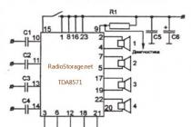
Typical switching circuit
Rice. 1. Schematic diagram of a typical inclusion of the TDA8571J chip.
Amplifier circuit on a TDA8571J chip
Amplifier Specifications:
- U pab = 14.4B(8-18B);
- Rн = 4 Ohm;
- I output peak = 7.5A;
- P type = 40W;
- F = 20... 20000 HZ;
- K.g. = 10% (at 20 W).
Allows switching on a bridge circuit. The microcircuit has built-in protection against overheating and short circuit (short circuit) in the load, as well as a diagnostic circuit.

Rice. 2. Schematic diagram of a simple power amplifier based on the TDA8571 chip.
Details for the low frequency amplifier on the TDA8571J chip:
- C1-C4: 0.47uF (film);
- C5: 0.1uF (film);
- C6: 2200-4700uF, 25V;
- R1: 10K.
It is possible to connect a circuit for electronic adjustment of the output power and turn off the microcircuit.
A wire is inserted into the holes marked with crosses before assembly and soldered on both sides.
At the "diagnostics" output, in case of overheating of the microcircuit or exceeding the output power, a low level signal appears, which can be used to control the operation of the amplifier.

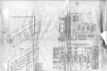
Rice. 3. Printed circuit board for the amplifier on the TDA8571 chip.
The ULF integrated microcircuit must be installed on a heat sink with an area of at least 200 cm ^ 2 in order to provide it with a good operating mode and reliable heat removal.
Amplifier on a chip TDA 2003
Everyone is familiar with the monoamplifier circuit on the TDA 2003 chip. It is used in various radio equipment: in TVs, computer speakers, car radios, etc. This microcircuit - the amplifier is powered by a voltage of 8 - 18 volts, the current consumption at rest is -50mA., The maximum 3A. Output power (Up=14V): - RL=4.0 Ohm - 6 W - RL=3.2 Ohm - 7.5 W - RL=2.0 Ohm - 10 W Analog - K174UN14.
A very simple ULF on two microcircuits and two transistors
The amplifier develops output power up to 25 watts per channel. It can work on a load of 3-10 ohms. In general, a good analog HI-FI amplifier SOI is not more than 0.03%
Simple Bass Amplifier
Amplifier Specifications:
Rated frequency range, Hz...............................63...12500. Rated input voltage, V.............................. 0.25. Rated input power, W, at a load with a resistance of 4 ohms with a harmonic coefficient of not more than 1% .............................................. 2.

UMZCH on TDA2005
A simple UMZCH on a cheap TDA2005 chip. It develops power up to 18W, works well from the car on-board network and from a laboratory source. It does not require adjustment - you just need to assemble it correctly, and do not forget about the radiator. The print is given "in the mirror" under the "laser iron". Capacitors for a voltage not lower than the supply voltage. I hope it's useful to someone.


Powerful ULF for the audio center
When making an audio center on your own or upgrading an existing one, developing an amplifier for a home theater, you may need a compact and powerful UMZCH module. In this sense, an amplifier made on the basis of the TDA 7294 chip is very convenient, such advantages of the chip as high output power, wide supply voltage range and
low level of harmonic distortion, combined with a very affordable price, make it attractive to use this
amplifier in many home-made designs of audio equipment, as well as in the repair and modernization of ULF equipment for industrial production.
Specifications:
2. Rated supply voltage +30V.
3. The maximum output power at a rated supply voltage at a load of 4 O, - 100W.
4. Input impedance 22 kOt.
5. Sensitivity 750 mV.
6. The coefficient of harmonic distortion at a power of 60W, no more than 0.5%.
7. Load resistance from 4 to 8 Ot.

By selecting R1 or R2, you can correct the sensitivity of the power amplifier. The amplifier turns on in a “soft way”
using switch S1. Switch S1 is one for both channels, if there are two channels, there simply will not be a second channel in the circuit
resistors R7 and R6, and the connection point of R4 and R5 is connected to a similar point of another channel.
Pins 5, 12 and 11 of the microcircuit are not used, so as not to complicate the layout of the board, they are not connected anywhere. They don't even have holes. They need to be bent up or removed. The radiator is extremely necessary, since during operation the microcircuit heats up very quickly and noticeably.
It is impossible to turn on the amplifier without a radiator even for a short time. At a power of about 100W, the surface area of the radiator must be at least 500 cm2. You can also use a radiator of a smaller surface, but ensure its forced airflow with a fan, for example, from a power source
personal computer
It is not necessary to isolate the heatsink from the chip, but only
if it is not connected to a common power wire or other live parts, except for the negative power bus. The fact is that the TDA7294 with a radiator plate "contacts" the negative power circuit.
ULF on the TDA7294 chip
TDA7294- the brainchild of SGS-THOMSON Microelectronics, this microcircuit is an AB class low-frequency amplifier, and is built on field-effect transistors. It is almost impossible to disable, in other words, burn it, it has protection against short circuit and overheating.
Of the advantages of TDA7294, the following can be noted:
output power 70W for a load with a resistance of 4 ohms, with distortion of 0.3-0.8%;
mute (Mute) and standby (Stand-By) functions;
low noise level, low distortion, frequency range 20-20000Hz, wide operating voltage range - ±10 - ±40V.


Powerful bridge ULF 4x40 W on TDA8571J

ULF is made on an integrated circuit TDA8571J (DA1). This IC is a class B ULF and is installed in auto-audio devices to obtain a high-quality medium-power music output signal. The microcircuit contains four identical bridge amplifiers developing power up to 40 watts into a 4 ohm load.
Amplifier characteristics
- operating voltage Upab = 14.4V (8-18V);
- nominal resistance Rн = 4 Ohm;
- frequency range F = 20... 20000 Hz

By closing the SW1 contacts, the microcircuit is transferred from standby to working mode and vice versa.
A characteristic feature of this microcircuit is the presence of a diagnostic output 9, which, in turn, made it possible to display the following emergency situations:
IC overload
IC overheating
Short circuit in load
Particular attention should be paid to connecting the amplifier to the power supply: the IC is extremely sensitive to the supply voltage - a maximum of 18 V. Reversing the polarity of the supply voltage leads to failure of the IC.
The amplifier chip must be installed on the heat sink. As a radiator, you can use a metal case or chassis of the device into which the ULF is installed. During installation, it is recommended to use heat-conducting paste type KTP-8.
Instead of the transistor VT1, KT3102, KT315 and the like are quite suitable; instead of VT2, KT3107, KT361 will go; LED - any