Good day, dear habrazhiteli!
This story began like this. While working at the facility, located in the building of a former factory (it seems to be metal structures) with a long name (and, of course, the name of the next great party leader), I saw one thing in a pile of rubbish intended for disposal. What thing hit me with a terrible attack of nostalgia, because exactly the same thing hung in the hall of the Special Design Bureau (with no less long and polysyllabic name than the above-mentioned plant), where my mother once worked, and where a lot of time passed from my childhood. Meet - watch "Electronics 7-06".
Of course, I could not resist the temptation to restore (and maybe modify?) them. Who is interested in the process, as well as the end result - I ask under the cut (carefully, a number of diagrams and photos!).
1. A bit of theory
The clock scheme is freely available on the Internet. The element base is the 176 series of microcircuits. Indicators - gas-discharge type IV-26. Below is the original diagram.
Rice. 1. Original circuit, part 1

Rice. 2. Original scheme, part 2
2. Let's start with
The clock was removed from the rubbish heap, taken home and dissected. After clearing the debris that had accumulated inside, this is what appeared to my eyes.


Turn on. Basically, everything works. But: the indicators burned out. There is nowhere to get the same IV-26. Google gives a lot of links telling us how to replace these IV-26s with LEDs, and even with ready-made seven-segment assemblies. Yes, but here's the bad luck - it looks completely different ... modernized and therefore looks poppy, I would say. Therefore, my number one task is to restore the indicators on the LEDs, while preserving the appearance as much as possible.
3. Scoreboard
When looking at the combs of wires leading to the scoreboard, as well as at the circuits of these scoreboards with diode adders, I feel a little uncomfortable. Difficult to set up, you can easily mix up the wires. Yes, and the outputs of the 176th series are rather weak in order to directly control the LEDs. Plus, I would like to be able to adjust the brightness of the display, preferably according to the scenario too - at night, high brightness is not entirely appropriate at home. No one guarantees me the stability of the reference oscillator on 25-year-old components either. Having estimated this and that, I decided to modify the scheme completely.Each indicator is a 7 x 11 LED matrix, so it comes out by the number of dots on the original IV-26. It is controlled by the well-known ATtiny2313. It also stores the images of characters for display, the character generator table, in other words. Even without any optimizations of 11 bytes per character, a hundred characters will definitely fit into it - which means that you can potentially write not only numbers on the scoreboard. And I will have 4 such matrices. And what to display, let them receive via UART. Well, actually what will count the time and send data for the scoreboard via this interface is later. I'll think about it later (c). But only 3 wires are suitable for each matrix - GND, + 5V and Data. I thought that a unidirectional transmission line for this task is quite enough.
The indication is dynamic, a 74HC595 register node is used to select rows, and a 74HC238 decoder is used to select a column. The design of the AVR + 74HC595 is well described and of no interest. Unfortunately, the SPI of tiny2313 is somehow cut, so loading data into registers is done programmatically. Plus, when trying to use SPI, there were problems with the layout of the board, so I abandoned this idea. The decoder is connected through a ULN2003 transistor assembly to increase power.
Initially, I planned to use an additional transistor controlled by hardware PWM on the T0 timer to adjust the brightness of the LEDs, but a problem arose: PWM, superimposed on the dynamic indication (their frequencies, of course, did not match), generated an unpleasant flickering of the LEDs. Therefore, PWM is software, and it is implemented using a column selection decoder. As you can see, the indicator has 7 columns, and the decoder has 8 outputs, and the last output is not connected. By choosing it, we extinguish the entire matrix.
LED current is limited by resistances. Based on the documentation for the applied LED-5213-PGC-6cd, 3 - 3.5V falls on them at a current of 20 mA, let's take an average of 3.2V. Plus another 1V drop on ULN2003. Total (5 - 3.2 - 1) / 0.02 = 40 ohms. I took 39 ohms.
The SA1 switches set the address of the board. This approach allows you to make all 4 boards the same.
Unfortunately, I have not yet mastered the metallization of holes at home. Therefore, the board is single-layer and the number of jumpers on it can be terrifying, although it was minimized by all efforts.
The circuit diagram is shown below.

Rice. 3. Schematic diagram of the indicator

And here is a photo of the board at one of the manufacturing stages (the photoresist has just been applied and developed).
The exchange protocol is very simple:
The first byte is always FF, which is the header of the packet.
The second byte is the address of the board.
The third byte is the data to be displayed, the character code according to ASCII.
Fourth - the desired brightness in the range 00 - FE.
At the end - the lower 8 bits from the sum of all bytes of the packet, integrity check. If the sum is FF, replace with FE. Package example:
FF 01 32 80 B2 - display the symbol "2" on the board with address 1, brightness - half of the maximum.
In the process of writing the code, I also came up with the idea to make the display board display its address at the time of start before receiving the first data. It turned out to be convenient for debugging.
4. Power supply
The native unit contains a transformer with two windings: one produces 22V, which were used to power the indicator anodes, and 3.8V to power their incandescences. Capacitors, of course, have lost their capacity, besides, we need + 5V. So, the scheme will have to be revised. In addition, it is possible to power the logic from 6 1.5V batteries so that the time does not go astray when the power is turned off. Batteries are kind of frivolous and require regular replacement, so I redesigned this unit to work with a standard 6V, 4.5 Ah battery.However, 22 * 1.41 = 31V. Well, the usual 7805 is not enough here, except that we also want to screw the function of a room heater here. A short googling, and the LM2576-5.0 comes to the rescue - an integrated switching regulator with an output current of up to 3A, which was even found in a local radio parts store.
A search for where I could steal and borrow a charger circuit for free in order to reduce the number of created bicycles led me here (in general, the site is dedicated specifically to bicycles, which in the context of the phrase smiles a little). However, the circuit is based on linear stabilizers ... however, there is a version of the aforementioned LM2576 with a tunable output voltage. In fact, you need to pile a source with a limitation of the form “output voltage is approximately 6 - 14V (with adjustment so that you can pick up a battery for 12V), the output current is not higher than 0.5A (also with adjustment)”. After some thought, something like this came up.

Rice. 4. Power supply circuit
Switching the "charging / battery operation" mode is performed by a conventional mechanical relay with a 220V winding connected in parallel with the primary winding of the power transformer. Somewhat naively, but, paradoxically, it works quite well.
5. The heart of the system
So the very “later” has come, in which I promised myself to think about what the actual time would be to count and manage the indicators. And even better if it also synchronizes it with the world. By NTP, for example. Or DAYTIME. Fortunately, there is Wi-Fi in the house. And most importantly, yes. I almost forgot. This watch still has one native display element, which is so touching that I considered it blasphemous to change it. For I can’t recreate the same, and he’s completely working. Flashing second dot on IV-4 indicator! She still needs to blink.I have been poking around the forums for a long time about pairing the AVR and Wi-Fi, watching how they did it on the Arduino ... but the price depresses me. And then my eyes fell on the “raspberry” bought for the purpose of studying with the subsequent creation of a torrent rocker, lying on a shelf ...
No, well, it's not even a cannon on sparrows. It's just a blow from the main caliber of the Death Star in order to destroy the evil bacteria under the rim of the toilet bowl. And on the other hand - does it matter where this torrent rocker will stand? There is more than enough space for a USB-HDD in the watch case. In addition, my experience with *nix systems is not very significant yet - a great opportunity to expand my horizons. About these thoughts flew through my head, and the fate of the raspberry was decided. Well, then let it show the street temperature, or something ... since I got hold of such capacities. Yes, and the sign generator of the scoreboard now allows you to draw pluses and minuses.
How to tie a real-time clock to rPi, as well as how to turn it on at all, carry out the initial configuration, install a torrent client there - it has been said many times before me. However, a number of links that seemed useful to me, I will still give below.
I take the street temperature from Rambler. The choice is due to the preferences of my soulmate.
So, step by step, all the actions with the "raspberry":
Here we read how to make friends with her Wi-Fi adapter TP-Link TL-WN725N.
And here is how to install a VNC server, it may come in handy.
it is intelligibly painted how to lift Samba.
And here is how to work with the built-in UART.
Here is a script that synchronizes time with the world using NTP.
timesync.sh
#!/bin/bash sudo service ntp stop sleep 5 sudo ntpdate time.nist.gov time.windows.com sleep 5 sudo service ntp start
This script reads the weather from Rambler, adding the received data to a file
getweather.sh
##!/bin/bash URL="http://api.rambler.ru/weather/informer?content_type=xml" FILENAME=/home/pi/clock/weather.dat WEATHER=$(curl $(URL) | grep -o -E "(
Main script, sends data via UART for display:
send.sh
#!/bin/bash DATAPATH=/home/pi/clock/weather.dat declare -i LOW_BRIGHT=5 declare -i HIGH_BRIGHT=100 send_data () ( DATA=$1 LEN=$(#DATA) stty -F /dev/ ttyAMA0 cs8 -cstopb raw speed 19200 > /dev/null for((i=0; i<$LEN; i++));
do
ADDRESS=$(printf "%d" $(($i+1)))
CHAR=$(printf "%d" ${DATA:$i:1})
if [ "$CHAR" = "0" ]
then
CHAR=32
fi
HOUR=$(date | cut -c 12-13)
if (("$HOUR" >"20")) || (("$HOUR"< "7"))
then
BRIGHTNESS=$(printf "%d" $LOW_BRIGHT)
else
BRIGHTNESS=$(printf "%d" $HIGH_BRIGHT)
fi
CHECKSUM=$((($ADDRESS+$CHAR+$BRIGHTNESS-1)%256))
if [ "$CHECKSUM" = "255" ]
then
CHECKSUM=254
fi
ADDRESS=$(printf "%o" $ADDRESS)
CHAR=$(printf "%o" $CHAR)
BRIGHTNESS=$(printf "%o" $BRIGHTNESS)
CHECKSUM=$(printf "%o" $CHECKSUM)
MESSAGE="\0377\0$ADDRESS\0$CHAR\0$BRIGHTNESS\0$CHECKSUM"
echo -ne "$MESSAGE$MESSAGE" >/dev/ttyAMA0 done ) if [ "$1" = "time" ] then HOUR=$(date | cut -c 12-13) MINUTE=$(date | cut -c 15-16) TIME="$(HOUR) $(MINUTE)" send_data $TIME exit 0 fi if [ "$1" = "weather" ] then WEATHER=$(cat $(DATAPATH)) if [ -z $(WEATHER) ] then echo "No weather info found" exit 0 fi send_data "$WEATHER" exit 0 fi if [ "$1" = "startup" ] then send_data "HELO" sleep 5 send_data "HABR" sleep 5 send_data " " exit 0 fi echo "Usage: send.sh time | weather | startup" exit 0
And - yes. We blink with a second point.
blink.sh
#!/bin/bash sudo echo "25" > /sys/class/gpio/export sudo echo "out" > /sys/class/gpio/gpio25/direction while true do echo "1" > /sys/class/gpio /gpio25/value sleep 0.5 echo "0" > /sys/class/gpio/gpio25/value sleep 0.5 done
Now let's add all this farming to cron:
# m h dom mon dow command 0/15 * * * * /home/pi/clock/timesync.sh 0/15 * * * * /home/pi/clock/getweather.sh * * * * * sleep 00; /home/pi/clock/send.sh time * * * * * sleep 10; /home/pi/clock/send.sh weather * * * * * sleep 15; /home/pi/clock/send.sh time * * * * * sleep 25; /home/pi/clock/send.sh weather * * * * * sleep 30; /home/pi/clock/send.sh time * * * * * sleep 40; /home/pi/clock/send.sh weather * * * * * sleep 45; /home/pi/clock/send.sh time * * * * * sleep 55; /home/pi/clock/send.sh weather
And... and that's it. Hang on the wall, enjoy, nostalgic. A photo of the process (clickable), as well as a traditional greeting to the residents of Habr can be seen below.
Attention! The author of the article had an artistic feeling cut out at birth, as a future engineer did not need it. Connoisseurs of clear horizons, composition of the frame and any other white balance, please stop reading at this point and go straight to the comments, in order to avoid serious mental trauma.

Mounting of indication boards on the chassis. Next to it is the power supply board.

We paint the rusted back covers.

The first inclusion in the assembled form. The boards display their addresses.

All elements are mounted on the chassis.

Larger, the same stage.

Packed in a case.
And - the logical conclusion!

Time.

Temperature outside.


All circuits, printed circuit boards and firmware can be taken
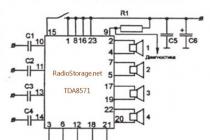
Schematic diagram of the clock is shown in fig. It contains three high-level integrated circuits of the K176 series, two transistors and 36 other discrete elements. Indicator - flat multi-digit, cathode-luminescent, with dynamic indication IVL1 - 7/5. It has four 21mm high digits and two separating dots arranged vertically.
The generator of second and minute pulses is made on a microcircuit - IMS1 K176IE18. In addition, this microcircuit creates pulses with a repetition rate of 1024 Hz (pin 11) used to operate the signaling device. To create an intermittent signal, pulses with a repetition rate of 2 Hz are used (pin 6). A frequency of 1 Hz (pin 4) creates the effect of "flashing" of the dividing points. Pulses with a repetition rate of 128 Hz, shifted relative to each other in phase by 4 ms (pins 1, 2, 3, 15) are fed to the grids of the four digits of the indicator, ensuring their consistent glow. Switching of the corresponding counters of minutes and hours is carried out with a frequency of 1024 Hz (pin 11). Each pulse applied to the indicator grids is equal in duration to two periods of a frequency of 1024 Hz, i.e. the signal supplied to the grid from the counters will be switched on and off twice. This selection of the frequency of in-phase pulses provides two effects: dynamic indication and pulse operation of the decoder and indicator.
Integrated circuit IMS2 K176IE13 contains counters of minutes and hours of the main clock, counters of minutes and hours for setting the time of the signaling device, as well as switches for switching the inputs and outputs of these counters. The outputs of the meters through the switch are connected to the binary code decoder into a seven-element indicator code. This decoder is made on the IMZ K176IDZ chip. The outputs of the decoder are connected to the corresponding segments of all four digits in parallel. When the button S2 “Call” is released, the indicator is connected to the hour counters (to recognize this mode, the dot flashes at a frequency of 1 Hz). By pressing the button S6 "Corr.", the hour counters (K176IE13 microcircuit) and the dividers of the minute pulse sequence generator (K176IE18 microcircuit) are set to the zero state. After releasing the S6 button, the clock will work as usual. Then, by pressing the buttons S3 "Min" and S4 "Hour", the minutes and hours of the current time are set. In this mode, it is possible to turn on the sound signal. When the button S2 "Call" is pressed, the counters of the signaling device are connected to the decoder and indicator. In this mode, four digits are also displayed, but the flashing dots go out. By pressing the button S5 "Bud" and holding it, press the buttons S3 "Min" and S4 "Hour" in sequence, set the required time for the alarm device to operate, observing the indicator readings. The clock circuit allows you to set a reduced brightness of the indicators using the S1 "Brightness" button. However, it should be remembered that when the brightness is reduced (button S1 is pressed), turning on the sound signal, as well as setting the time of the clock and the alarm device is not possible.
The power supply unit BP6 - 1 - 1 contains a network transformer T, which creates a voltage of 5 V (with a midpoint) to power the glow of the indicator cathode and a voltage of 30 V to power the rest of the indicator circuits and microcircuits. A voltage of 30 V is rectified by a ring circuit on four diodes (VD10 - VD13), and then, using a stabilizer on a zener diode VD16, a voltage of +9 V is created relative to the "case" to power the microcircuits, and using a stabilizer on zener diodes VD14, VD15 and a transistor VT2 - voltage + 25 V (relative to the cathode) for powering grids and indicator anodes. The power consumed by the clock is not more than 5 watts. A backup power connection is provided to save the time of the clock when the network is turned off. Any 6…9V battery can be used.
Literature MRB1089
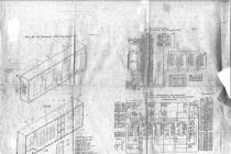
Your attention - two electrical circuit diagrams of the Soviet watch "Electronics G 9.02" (Appendix 1 and Appendix 2). Originals, whole.
You are guaranteed to get what you see in the photo!
ATTENTION! After the end of the auction, the buyer will be the first to contact within three days. Shipping of this item is at the buyer's expense 100% prepaid. Payment within three working days after the invoice is issued. Payment is made in full, i.е. cost of goods + shipping, if not otherwise preliminary agreements. Lot forwarding only in Russia. We are not responsible for the mail, as well as for the quality of delivery.
Terms of payment: To a Sberbank or Alfa-Bank card
By placing a bid, you confirm that you have read the description, photos and shipping conditions of this lot. If you have any questions - ask them BEFORE buying or BEFORE placing a bid, through the "Ask seller a question" option. No claims will be accepted after the end of the auction!
THE COST OF POSTAGE EXPENSES IS INDICATED ONLY FOR THIS SUBJECT! When buying several lots at the same time, you save a lot on postage, but the final cost of sending several lots may be higher than indicated for this item! If the Buyer does not receive the goods at the post office (where it is stored for a month) and returns it to the Seller, the transaction is considered completed and the money is not returned. PERSONAL MEETINGS WITH BUYERS ARE EXCLUDED!
Description of electronic watch repair Janus, made in the USSR. The basis of this clock is the K145IK1901 microcircuit - a common Soviet controller for building electronic clocks. Time is displayed on the big indicator IVL1-7/5 of green color. Based on the experience of working and repairing such watches, it can be concluded that most often the quartz resonator fails, the electrolytic capacitors dry out, and the electrovacuum indicators die out. Indicators that failed due to a burned out filament have not yet come across. Of course, it is best to repair any electronics with a circuit. Here are two similar diagrams. If anything, the K145IK1901 and KR145IK1901 microcircuits are interchangeable during repairs.
The second version of the scheme

Assignment of control buttons
- SB1- "M" - setting the current time in minutes, in the "T" mode - in seconds;
- SB2- "H" - setting the current time in hours, in the "T" mode - in minutes;
- SB3- "K" - correction of the current time;
- SB4- "C" - stopwatch mode;
- SB5- "O" - stop indication;
- SB6- "T" - timer mode;
- SB7- "B1" - the "alarm clock 1" mode, the time is set using the "H" and "M" buttons.
- SB8- "B" - calling the indication of the current time, for example, after setting alarms;
- SB9- "B2" - "alarm clock 2" mode.


In this case, the clock lay idle for a long time and finally, after 5 years, it was needed. At first, there was an idea to buy ready-made LED ones - with large numbers, 5-10 centimeters high. But looking at the price for 1000 rubles, I realized that it was better to revive the old ones.


We disassemble the case and inspect the circuit with details - everything is quite complicated, compared to modern ones. The power supply seems to be simple - transformerless, but then the reduced voltage of 10 V is converted by a very cunning inverter on a multi-winding ring into 27 volts of power supply for the IVL-1 indicator anode.

There are no signs of life, the fuse and diodes are normal, but the power supply to the filter capacitor (1000 microfarads 16 V) is only 4 volts.

We take a laboratory adjustable power supply and supply the clock with the voltage of 10 V set according to the scheme, controlling the current. Everything worked - the indicator lit up and the point of seconds began to flash. The current was about 80 mA.

Obviously the problem is with the capacitor. And the culprit was not the filter electrolyte, as you might immediately think, but a ballast network that had almost lost its capacity, at 400 V 1 microfarad. At the same time, a second similar one was soldered to him, and when connected to a 220 V network, the device started working. The voltage immediately rose to 10.4 V.

On this, the repair can be considered completed, and the 1000 rubles already allocated for the purchase can be considered saved. From this we conclude: do not be lazy to repair household appliances and electronics on your own, because in addition to saving money on buying a new one, you will feel the joy of a job well done and pride in your home :)