Repair GS-8300
In this article we will repair the "tricolor" receiver with our own hands. Often the problem arises that the warranty period has expired and the receiver suddenly breaks down. It is expensive to buy a new receiver, to carry it to a service center means to deprive yourself of watching satellite TV for a long time. But in many cases, the breakdown of the device can be corrected independently, without spending much effort and a lot of money. If you know how to solder, then it is easier to figure out the faults yourself and fix them.
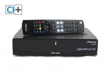
As an example, we will use the Tricolor TV receiver GS-8300 N. It should be noted that the quality of the receiver leaves much to be desired, since it costs decently. Nevertheless, many subscribers use this particular receiver, and not all of them work properly.
we will use the receiver for television "Tricolor TV" GS-8300
The main and most common problem with most receivers is a malfunction in the power supply and voltage conversion system. In addition, a short circuit in the coaxial cable from the LNB will often cause damage to the modulator. Only in the latest models they began to use good protection, which, when closed, stops the voltage supply to the converter until this short circuit is eliminated.
So, a problem arose: the receiver does not turn on and does not show any signs of life at all, and the indicators on the front panel are off. We tried to twist the plug from the socket, turn on / off the toggle switch - it does not help.
Then let's understand further. First, be sure to unplug the plug and remove the top cover with a screwdriver. We need to look at the electronic stuffing of the device. It is important to remember here that when removing the cover, we will definitely break the warranty seal.
Therefore, if the warranty period has not yet expired, it is better not to try it yourself, otherwise you will not be able to repair your receiver under warranty later.
And if the guarantee has passed and you have no one to hope for, then go for it - break the seal.
Tricolor TV GS-8300
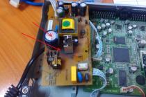
Removing the cover reveals circuit boards with various components. They are interconnected by wire busbars. The photo shows some devices with a description. We need to find the power board. It has a transformer and an inlet for the power cord, so it's not difficult to find it. The first thing to look out for is the fuse, which is usually installed at the beginning of the circuit. The fuse can take many forms, such as a glass capsule with a conductor or a small plastic box that contains the fuse. In the second case, you must first remove the cover of the box (you can use tweezers or tweezers) to get to the fuse itself. Next, you need to check the fuse for a break with a tester or multimeter. If it blows out, which often happens, then go to the radio store, buy the same fuse and just change it. If everything is fine with the fuse, then we check further along the circuit.
Another element that often breaks down is the transformer itself. Such a fault is detected by measuring the voltage on the secondary winding. It is worth noting that not everyone can do the replacement of the transformer. If you are not sure that you can change it yourself, then it is better to take your receiver to a repairman, and if this does not seem difficult for you, then go for it.
Internal structure of the receiver
Internal structure of the receiver
Internal structure of the receiver
Another malfunction is the failure of the electrolytic or oxide capacitor at the input due to drying out. To detect this breakdown, you need to understand at least a little bit of radio mechanics. A defective capacitor is usually yellowish in color, and a small brown spot can be observed at the base of its legs on the board. In addition, you can compare the rated and measured capacitance of a capacitor to determine if it is working properly.
The diode bridge in the receiver converts the AC mains current into direct current.
The diode bridge can also break. This is easy to check, since a semiconductor diode has one main function: to pass current in one direction, but not in the other.
In the case we are considering, a breakdown occurred with the transistor of the primary winding of the transformer. It has a heatsink to dissipate heat, so it's pretty easy to find. The malfunction was detected as follows: they measured the voltage at the emitter of the transistor, it was not there, the primary winding was not powered, which means that all other parts are de-energized. The cost of the transistor is about 30 rubles. To replace it we need a soldering iron. We eliminate the malfunction, and - "Hurray! It works! " - the receiver is ok again. Note that the transistor does not break down often, mainly receivers fail due to a fuse.
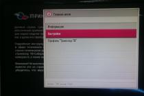
Let's consider another very common malfunction - firmware crash. This happens quite often. A sign of a firmware rally is a complete hang of the receiver. Then we just need to reflash the receiver.
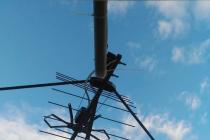
The reason for the breakdown of the receiver can also be poor-quality, unprofessional installation. If the outer insulation of the cable is broken, then rainwater or snow can easily penetrate into the cable and, like a hose, seep into the receiver, filling all its internal contents. Therefore, you need to monitor the cable, whether there are any kinks or insulation faults.
Those who do not understand anything about the internal structure of satellite receivers, or who have no time to deal with this at all, should not despair if the device breaks down. Service centers have not been canceled yet. There you can contact your problem and the specialists will help you solve it.
Receivers fail for various reasons
Receivers fail for various reasons - this is a voltage drop, and wear and tear of the device itself due to intensive use, and the failure of certain elements. This also includes breakdowns due to owners who themselves decided to figure out the problem without having special skills, for example, they incorrectly replaced the firmware in a satellite or cable receiver.
The power supply is, perhaps, the most breakable part of the receiver. The power supply can break due to a poor-quality supply network, due to poor-quality radio components (especially on cheap Chinese equipment).
Dust and dirt can also cause the receiver to break, creating an incorrect thermal regime.
Dust and dirt in the receiver can also damage the receiver.
The service center repairs and maintains various satellite equipment. Moreover, the repair is carried out by specialists and on professional equipment. Almost any defective part can be replaced with a new one. Repair times will depend on the availability of parts at the service center. If any part is missing, then it will be ordered from suppliers, which will take some time. But in large, serious centers, usually, parts are always in stock.
Consider another situation: the receiver failed after a power surge. After opening the cover, the following parts were found to have burned out:
network capacity C5 - 47µFx400V
R8, R11, R13 - 3 Ohm each (frame size 1206)
R9 - 47 Om (1206)
U1 - no type defined
On the Internet, we found a page with a table on the identification and selection of analogs (for example, http://remont-aud.net/ic_power/), using it we look at what we have and what we don’t have. We will replace the last part with SG6848 to minimize interference with the factory circuit.
We carry out dismantling of faulty parts (circled in red in the photo):
R8, R11, R13 - 3 Om (1206)
R3, R6 (one of them is possible) - 1 MOm (1206)
C3 - 68nF
R25 - 3.6 kOm (0805)
R26 - 10 kOm (0805)
Installing new children
instead of U1 - SG6848
instead of R8, R11, R13 - one resistor 1.8 Om x 0.5W
instead of C3 a 100 kOm resistor (1206)
instead of R26 a 33 kOm resistor
instead of R25 we select a resistor in the range of 10-12 kOm, controlling the voltage 3V3 at the cathode VD8, we will stop at the nominal value of 11 kOm, U = 3.36V (at 10 kOm U = 3.28V, at 12 kOm U = 3.41V)
instead of the burnt out Q1 - SSS4N60B (TO-220F package).
Installing new parts in the receiver
Power supply diagram GS-8300
Repair of the Tricolor GS8300 receiver
Hello everyone. Today I will show the solution to how it turned out to be a common problem. One fine morning, about to watch TV, I was upset by a black screen. Looking at the receiver of the tricolor, he noticed that he seemed to be dead. 🙂
The GS8300N receiver did not respond to power supply (LEDs did not light up). Since the warranty ended long ago, I began to disassemble this device. The picture was unpleasant, the receiver's power supply burned out. This receiver, like the TV, was powered through a voltage regulator from the date of purchase, however, this did not save it.
 The power supply capacitor dried up and swelled, several radioelements burned out from overheating.


In order not to breed plagiarism with the text, I will post a video that helped me quickly repair the receiver's power supply. It describes the repair process in detail. In addition, the circuit has been slightly redone and works great.
I will show you the cost of repairs, and then decide for yourself whether it is worth it or not.
- Microcircuit - 60 rubles
- Diode - 2 rubles.
If the arms are straight, then it's worth it!
After checking the diodes, I found one broken.

Here is the original diagram of the receiver's power supply.

And here it is, the video! 🙂
If it came in handy, I'm always glad for thanks. If something is not clear, I will definitely answer in the comments. I got it right the first time and this redesigned circuit works fine.

Be sure to check out here:
- Do-it-yourself washing machine repair Hello everyone. Let me introduce you to a short instruction in which I will tell you how to replace faulty bearings in a washing machine drum. […]
- Repair of the gas water heater Neva Transit Hello everyone. I have not written anything useful for a long time and I hasten to provide you with a small manual for correcting one malfunction in gas water heaters. Or rather two [...]
- Starting the plotter for the first time First, a little background. Our organization purchased an HP Designdjet T1300 plotter about a year ago. For a long time he stood in the package, while the place was determined where [...]
SUPRA STV-LC42T400FL (V1N06)
Main HK.-T.SP9202P53
OB3350CP backlight driver
Malfunction:
In the TV, the backlight is turned off, the sound and the image remain, you can see it on the MENU matrix.
The backlight is turned off arbitrarily, the backlight can go out right away, or it can work for half an hour. (According to the client)
In a workshop:
Upon admission to the repair, the TV worked for 5 minutes and the backlight turned off.
The solution to the problem did not come immediately.
The first thing I thought about was LEDs!
Opened the cover, checked the voltage on OB3350CP
All voltage is normal when the backlight is on!
When the backlight turns off, the voltage at 2 leg is 0 volts
I decided to open the panel to look at the LEDs ...
Checking the result with the device did not reveal the exact result, it seems that all the LEDs are normal for the current, there is no large discrepancy, all the strips glow perfectly.
The only thing that alerted me and caught my eye was that this place in the circle of diodes was clearly burnt, on some slats it was more noticeable, on others less.
In general, I installed all the bars on the panel again and turned it on without a matrix! UPS ... The LEDs blinked and did not light up.
But before disassembling the panel, the backlight worked for two or three minutes and turned off.
Checked EVERYTHING again! No problems, all the rules. I decided to check each LED separately for current consumption, I did not find any critical differences.
Well maybe? The TV worked, personally took it for repairs and saw the perfect picture together with the client.
And now all the LEDs flash and immediately go out, the LED on the TV panel lights up green, that is, the TV remains in working mode, you can turn it off from the remote control and turn it on again, then the backlight turns on and off abruptly again, the time is no more than 2 seconds.
I checked again the voltage on the OB3350CP driver, everything is normal, except for the voltage on the 2nd leg there it appears for a second and immediately disappears.
I decided that the problem is in the microcircuit itself or in the LEDs. There was no such driver available, I decided to change the LEDs for new ones, since I bought it recently.
Further, replacing the LEDs did not give a result, everything is the same, the backlight blinks and immediately goes out.
I bought two OB3350CPs, changed all two in turn, but the result is the same.
I decided that there was a problem with the mine, but to clear my conscience I decided to check again the entire OB3350CP harness. I cleaned the glue on the backlight connectors, there are also resistors, washed everything with alcohol and let's go around under the microscope .... all the rules!
Only one resistor raised doubts, according to the marking it is 01C (10 kΩ), but when tested for Ohms it behaves strangely, it increases, then decreases to the norm of 10 kΩ.
Once again, I washed everything and soldered this resistor and finally it went to MΩ.
All repairs are completed, the TV is assembled and put on run!
In the photo, the problem resistor was highlighted, there was no circuit during the repair, so OB3350CP rang like the third leg.
In general, nothing new, who does not work and is not mistaken)) Just repairs ..., I think in this chassis it will be another trick thanks to the quality of the resistors marked 01C.
The Ferex R&D FP09T001 Rev.2 power supply for receivers is assembled according to the circuit of a pulsed flyback voltage converter shown in Fig. 12. Input mains alternating voltage 190 ... 240 V with a frequency of 50 or 60 Hz through a fuse-link F1, an interference suppression filter C1LF1, which prevents the penetration of noise from the source into the network, a current-limiting resistor RT1 and a diode bridge D1-D4 are fed to a smoothing capacitor C5.
GS-8300 satellite receiver power supply circuit
Series resistor RT1 limits the inrush current through diode bridge D1-D4 while charging capacitor C5. Varistor RV1 protects the source from overvoltage. When the supply voltage exceeds the permissible value, the resistance of the varistor decreases, the current flowing through it increases and the fusible link F1 burns out.
The rectified DC voltage passes through the control unit to the primary winding of the transformer T1. It is switched by a powerful field-effect transistor Q1, which is controlled by the PWI controller U5. The energy stored in the transformer is transferred to the secondary windings and rectified by diodes D5. D7-D9.
To start the power supply when connected to the network, a rectified voltage is used, which comes through the current-limiting resistors R4, R5 to pin 5 of the U5 microcircuit. After starting, a voltage appears on the secondary windings of the transformer T1, and the U5 microcircuit is powered by the voltage rectified by the diode D5, through the current limiting resistor R19.
The stabilization of the output voltages of the power supply is provided by the elements U2 (optocoupler, galvanically decoupling the primary and secondary circuits of the source) and U3 (voltage stabilizer). The rated values of the output voltages are set by the divider R25R26. When they increase during operation, the transistor in the optocoupler U2 opens, and the ShI controller U5 decreases the duration of the pulses that open the transistor Q1.
As a result, the energy transferred to the secondary circuits decreases and, consequently, the output voltages decrease. A +5 V linear voltage regulator is assembled on a powerful field-effect transistor Q2 and a U4 microcircuit. Its nominal output voltage is set by the R35R38 divider. The external view of the power supply is shown in Fig. 13.
Repair of the tricolor GS8300 receiver. Alteration of the power supply. A typical malfunction of the tricolor gs8300 receiver is very common and consists in the failure of the power supply. The repair of this power supply is sometimes quite difficult due to the fact that there is no original PWM microcircuit for the controller. But it can be converted to another available 5L0380 microcircuit with changes in the installation of the power supply. Release partner TAGGSM.RU http://goo.gl/rUoVNb TexRemont - a simple solution to computer problems Many users in the event of a breakdown of a computer, laptop or LCD TV immediately turn to specialists who can repair it all. On the one hand, this is correct, but on the other hand, the cost of even the simplest repair, such as replacing the BIOS battery, will not be minimal. Therefore, for users who are not afraid to pick up a soldering iron and a screwdriver, a special channel has been created https://www.youtube.com/user/texremont1. When a laptop or tablet malfunctions, not everyone knows the intricacies of not only the repair and the procedure for disassembling devices. On the TexRemont channel, you can watch hundreds of videos dedicated to this issue. They contain video instructions in which professionals show in detail the features of working with a variety of models of laptops, video cards and motherboards from different manufacturers. At the same time, the main problems and ways of solving them that may arise during operation are described. A detailed description of the disassembly of laptops and tablets of various brands from different manufacturers can also be viewed without any problems. Not every person can boast of one. That he knows how to work with such a rather simple device as a soldering iron, especially a soldering station. The peculiarities of using modern infrared stations are described on the TexRemont channel, and at the same time you can always watch detailed video tutorials related to such an important feature as chip reballing, which is the basis of modern precision electronics. Repair of computers and their components is a rather complicated and time-consuming process that requires skills and experience. The TexRemont channel describes in detail the basic actions in those situations when a computer fails at the hardware level. The channel describes in detail the features of modernizing computers, connecting various devices and gadgets. Hundreds of videos will help a novice electronics engineer to choose the right equipment for the repair of computer and digital equipment and teach how to work with it. A detailed description of modern technologies of soldering and installation of equipment will teach anyone who wants to independently repair laptops and computers. Our partner Youpartnerwsp