Power lines
Power line(Power transmission line) - one of the components of the electrical network, a system of power equipment designed for the transmission of electricity.
According to MPTEEP (Interindustry rules for the technical operation of electrical installations of consumers) Power line- An electrical line extending outside the power plant or substation and intended for the transmission of electrical energy.
Distinguish air and cable power lines.
Power transmission lines also transmit information using high-frequency signals; according to estimates, about 60 thousand high-frequency channels are used in Russia over power transmission lines. They are used for dispatch control, transmission of telemetric data, relay protection signals and emergency control automation.
Overhead power lines

Overhead power line(VL) - a device designed for the transmission or distribution of electrical energy through wires in the open air and attached with the help of traverses (brackets), insulators and fittings to supports or other structures (bridges, overpasses).
VL composition
- Sectioning devices
- Fiber optic communication lines (in the form of separate self-supporting cables, or built into the lightning protection cable, power wire)
- Auxiliary equipment for the needs of operation (equipment high frequency communication, capacitive power take-off, etc.)
Documents regulating overhead lines
VL classification
By the nature of the current
- AC overhead line
- DC overhead line
Basically, overhead lines are used for the transmission of alternating current and only in some cases (for example, for communication of power systems, power supply of the contact network, etc.) they use direct current lines.
For AC overhead lines, the following scale of voltage classes is adopted: variable - 0.4, 6, 10, (20), 35, 110, 150, 220, 330, 400 (Vyborg substation - Finland), 500, 750 and 1150 kV; constant - 400 kV.
By appointment
- ultra-long-distance overhead lines with a voltage of 500 kV and above (designed to connect individual power systems)
- trunk overhead lines with a voltage of 220 and 330 kV (designed to transfer energy from powerful power plants, as well as to connect power systems and combine power plants within power systems - for example, they connect power plants with distribution points)
- distribution overhead lines with a voltage of 35, 110 and 150 kV (intended for power supply of enterprises and settlements of large regions - they connect distribution points with consumers)
- Overhead lines 20 kV and below, supplying electricity to consumers
By voltage
- Overhead lines up to 1 kV (overhead lines of the lowest voltage class)
- Overhead lines above 1 kV
- OHL 1-35 kV (OHL of middle voltage class)
- VL 110-220 kV (VL high class voltages)
- Overhead lines 330-500 kV (overhead lines of ultra-high voltage class)
- Overhead lines 750 kV and above (overhead lines of ultra-high voltage class)
These groups differ significantly, mainly in terms of design conditions and structures.
By the mode of operation of neutrals in electrical installations
- Three-phase networks with ungrounded (isolated) neutrals (the neutral is not connected to the grounding device or is connected to it through devices with high resistance). In Russia, such a neutral mode is used in networks with a voltage of 3-35 kV with low currents of single-phase earth faults.
- Three-phase networks with resonant-grounded (compensated) neutrals (the neutral bus is connected to ground through inductance). In Russia, it is used in networks with a voltage of 3-35 kV with high currents of single-phase earth faults.
- Three-phase networks with effectively earthed neutrals (high and extra-high voltage networks, the neutrals of which are connected to earth directly or through a small resistance). In Russia, these are networks with voltages of 110, 150 and partially 220 kV, i.e. networks in which transformers are used, and not autotransformers, requiring mandatory solid grounding of the neutral according to the mode of operation.
- Networks with a solidly grounded neutral (the neutral of a transformer or generator is connected to the grounding device directly or through a low resistance). These include networks with a voltage of less than 1 kV, as well as networks with a voltage of 220 kV and above.
According to the operating mode depending on the mechanical state
- Overhead lines of normal operation (wires and cables are not broken)
- Overhead lines for emergency operation (with full or partial breakage of wires and cables)
- Overhead lines of the installation mode of operation (during the installation of supports, wires and cables)
Basic elements of overhead lines
- Track- the position of the overhead line axis on the earth's surface.
- Pickets(PC) - the segments into which the route is divided, the length of the PC depends on the nominal voltage of the overhead line and the type of terrain.
- Zero picket mark marks the beginning of the track.
- Center mark denotes the center of the location of the support in nature on the route of the overhead line under construction.
- Production picketage- installation of picket and center marks on the route in accordance with the list of supports placement.
- Support foundation- a structure embedded in the ground or resting on it and transferring loads to it from the support, insulators, wires (cables) and from external influences (ice, wind).
- Foundation base- the soil of the lower part of the excavation, taking the load.
- Span(span length) - the distance between the centers of the two supports on which the wires are suspended. Distinguish intermediate(between two adjacent intermediate supports) and anchor(between anchor supports) spans. Transition span- a span crossing any structure or natural obstacle (river, ravine).
- Line rotation angle- the angle α between the directions of the overhead line route in adjacent spans (before and after the turn).
- Sag- the vertical distance between the lowest point of the wire in the span and the straight line connecting the points of its attachment on the supports.
- Wire size- the vertical distance from the lowest point of the wire in the span to the crossed engineering structures, the surface of the earth or water.
- Plume (a loop) - a piece of wire connecting the tensioned wires of adjacent anchor spans on the anchor support.
Cable power lines
Cable power line(CL) -called a line for the transmission of electricity or its individual pulses, consisting of one or more parallel cables with connecting, stop and end couplings (terminations) and fasteners, and for oil-filled lines, in addition, with feeding devices and a pressure alarm system oils.
By classification cable lines are similar to overhead lines
Cable lines are divided according to the conditions of passage
- Underground
- By structures
- Underwater
cable structures include
- Cable tunnel- a closed structure (corridor) with supporting structures located in it for placing cables and cable sleeves on them, with a free passage along the entire length, allowing for laying cables, repairing and inspecting cable lines.
- Cable duct- closed and buried (partially or completely) into the ground, floor, ceiling, etc., an impenetrable structure intended for placing cables in it, laying, inspection and repair of which can only be performed with the floor removed.
- Cable shaft- a vertical cable structure (usually of rectangular cross-section), whose height is several times greater than the side of the cross-section, equipped with brackets or a ladder for people to move along it (through shafts) or a fully or partially removable wall (non-through shafts).
- Cable floor- the part of the building bounded by the floor and the ceiling or covering, with a distance between the floor and protruding parts of the ceiling or covering of at least 1.8 m.
- Double floor- a cavity bounded by the walls of the room, the interfloor overlap and the floor of the room with removable plates (over the entire or part of the area).
- Cable block- cable structure with pipes (channels) for laying cables in them with associated wells.
- Cable camera- underground cable structure, closed with a deaf removable concrete slab, designed for laying cable sleeves or for pulling cables into blocks. A chamber that has a hatch to enter it is called a cable well.
- Cable trestle- overground or ground open horizontal or inclined extended cable structure. The cable rack can be passable or non-passable.
- Cable gallery- overground or above-ground closed in whole or in part (for example, without side walls) horizontal or inclined extended cable through passage.
By type of insulation
Insulation of cable lines is divided into two main types:
- liquid
- cable oil oil
- solid
- oil-paper
- polyvinyl chloride (PVC)
- rubber-paper (RIP)
- cross-linked polyethylene (XLPE)
- ethylene propylene rubber (EPR)
Insulation with gaseous substances and some types of liquid and solid insulation are not indicated here due to their relatively rare use at the time of this writing.
Losses in power lines
The loss of electricity in the wires depends on the current strength, therefore, when transmitting it over long distances, the voltage is repeatedly increased (by the same time reducing the current strength) using a transformer, which, when transmitting the same power, can significantly reduce losses. However, with an increase in voltage, various kinds of discharge phenomena begin to occur.
Another important quantity affecting the efficiency of transmission lines is cos (f) - a value that characterizes the ratio of active and reactive power.
EHV overhead lines have active corona losses (corona discharge). These losses largely depend on weather conditions (in dry weather, the losses are less, respectively, in rain, drizzle, snow, these losses increase) and the splitting of the wire in the phases of the line. Corona losses for lines of different voltages have their own values (for a 500 kV overhead line, the average annual corona losses are about ΔР = 9.0 -11.0 kW / km). Since the corona discharge depends on the tension on the surface of the wire, phase splitting is used to reduce this tension in overhead lines of super-high voltage. That is, in place of one wire, three or more wires in a phase are used. These wires are located at an equal distance from each other. It turns out the equivalent radius of the split phase, this reduces the tension on the individual wire, which in turn reduces the corona losses.
- (VL) - power line, the wires of which are supported above the ground with the help of supports, insulators. [GOST 24291 90] Term heading: Power equipment Encyclopedia headings: Abrasive equipment, Abrasives, Roads ... Encyclopedia of terms, definitions and explanations of building materialsAIR POWER LINE- (power line, power transmission line, a structure designed to transmit electrical energy over a distance from power plants to consumers; located in the open air and usually made with bare wires, which are suspended with ... ... Big Polytechnic Encyclopedia
Overhead power line- (VL) a device for the transmission and distribution of electricity through wires located in the open air and attached with insulators and fittings to supports or brackets, racks on engineering structures (bridges, overpasses, etc.) ... Official terminology
overhead power line- 51 overhead power lines; Overhead transmission line Power line, the wires of which are supported above the ground by means of supports, insulators 601 03 04 de Freileitung en overhead line fr ligne aérienne
The main elements of overhead lines are wires, insulators, linear fittings, supports and foundations. On overhead lines of alternating three-phase current, at least three wires are suspended, making up one circuit; on overhead direct current lines - at least two wires.
By the number of circuits, overhead lines are subdivided into one, two and multi-circuit. The number of circuits is determined by the power supply scheme and the need for its redundancy. If the power supply scheme requires two circuits, then these circuits can be suspended on two separate single-circuit overhead lines with single-circuit supports or on one double-circuit overhead line with double-circuit supports. The distance / between adjacent supports is called a span, and the distance between anchor-type supports is called an anchor section.
The wires, suspended on insulators (A, - the length of the garland) to the supports (Figure 5.1, a), sag along the catenary. The distance from the suspension point to the lowest point of the wire is called the sag /. It determines the size of the approach of the wire to the ground A, which for a populated area is equal to: to the surface of the earth up to 35 and PO kV - 7 m; 220 kV - 8 m; to buildings or structures up to 35 kV - 3 m; 110 kV - 4 m; 220 kV - 5 m. The span length / is determined by economic conditions. The span length up to 1 kV is usually 30 ... 75 m; PO kV - 150 ... 200 m; 220 kV - up to 400 m.
Varieties of power transmission poles
Depending on the method of suspension of the wires, the supports are:
- intermediate, on which the wires are fixed in supporting clamps;
- anchor type, used for tensioning wires; on these supports, the wires are fixed in tension clamps;
- angular, which are installed at the angles of rotation of overhead lines with a suspension of wires in supporting clamps; they can be intermediate, branch and corner, end, corner anchor.
Enlarged, the overhead line supports above 1 kV are divided into two types of anchor ones, which fully perceive the tension of wires and cables in adjacent spans; intermediate, not perceiving the tension of the wires or partially perceiving.
On overhead lines, wooden supports are used (Figure 5L, b, c), wooden supports of a new generation (Figure 5.1, d), steel (Figure 5.1, e) and reinforced concrete supports.

Wooden poles of overhead lines
Wooden poles of overhead lines are still common in countries with forest reserves. The advantages of wood as a material for supports are: low specific weight, high mechanical strength, good electrical insulating properties, natural round assortment. The disadvantage of wood is its rotting, to reduce which antiseptics are used.
An effective method of combating decay is the impregnation of wood with oily antiseptics. In the USA, the transition to glued wooden poles is under way.
For overhead lines with a voltage of 20 and 35 kV, on which pin insulators are used, it is advisable to use single-column candle-shaped supports with a triangular arrangement of wires. On overhead transmission lines 6 -35 kV with pin insulators, for any arrangement of wires, the distance between them D, m, should not be less than the values determined by the formula
where U - lines, kV; - the largest sag arrow corresponding to the overall span, m; B - ice wall thickness, mm (no more than 20 mm).
For overhead lines 35 kV and above with suspended insulators with a horizontal arrangement of wires, the minimum distance between the wires, m, is determined by the formula
The stand of the support is made of a composite: the upper part (the stand itself) is made of logs 6.5 ... 8.5 m long, and the lower part (the so-called stepson) is made of reinforced concrete with a section of 20 x 20 cm, 4.25 and 6.25 m long or from logs 4.5 ... 6.5 m long. Composite supports with a reinforced concrete stepchild combine the advantages of reinforced concrete and wooden supports: lightning and decay resistance at the point of contact with the ground. The connection of the rack with the stepson is performed with wire ties made of steel wire with a diameter of 4 ... 6 mm, tensioned by means of a twist or a tension bolt.
Anchor and intermediate corner supports for 6-10 kV overhead lines are made in the form of an A-shaped structure with composite posts.
Steel Power Transmission Poles
They are widely used on overhead lines with a voltage of 35 kV and above.
By design, steel supports can be of two types:
- tower or single-column (see Fig.5.1, e);
- portal, which, according to the method of fastening, are subdivided into free-standing supports and supports on guys.
The advantage of steel supports is their high strength, the disadvantage is their susceptibility to corrosion, which requires periodic painting or application of an anti-corrosion coating during operation.
Supports are made of rolled steel (an isosceles corner is mainly used); high transition supports can be made of steel pipes. In the joints of the elements, a steel sheet of various thicknesses is used. Regardless of the design, steel supports are made in the form of spatial lattice structures.
Reinforced concrete transmission towers
Compared to metal ones, they are more durable and economical in operation, since they require less maintenance and repair (if we take the life cycle, then reinforced concrete ones are more energy intensive). The main advantage of reinforced concrete supports is a decrease in steel consumption by 40 ... 75%, the disadvantage is a large mass. According to the manufacturing method, reinforced concrete supports are subdivided into concreted at the installation site (for the most part, such supports are used abroad) and factory-made.
The fastening of the traverses to the trunk of the reinforced concrete support is performed using bolts passed through special holes in the rack, or with the help of steel clamps covering the trunk and having trunnions for attaching the ends of the traverse chords to them. Metal traverses are hot-dip galvanized, so they long time do not require special care and supervision during operation.
The wires of overhead lines are made uninsulated, consisting of one or more twisted wires. Single-wire wires, called single-wire (they are made with a cross section of 1 to 10 mm2), have a lower strength and are used only on overhead lines with a voltage of up to 1 kV. Stranded wires, twisted from several wires, are used on overhead lines of all voltages.
The materials of wires and cables must have a high electrical conductivity, have sufficient strength, withstand atmospheric influences (in this respect, copper and bronze wires have the greatest resistance; aluminum wires are subject to corrosion, especially on the seashore, where the air contains salts; steel wires are destroyed even under normal atmospheric conditions).
For overhead lines, single-wire steel wires with a diameter of 3.5 are used; 4 and 5 mm and copper wires up to 10 mm in diameter. The limitation of the lower limit is due to the fact that wires of smaller diameter have insufficient mechanical strength. The upper limit is limited due to the fact that bends of a single-wire wire of larger diameter can cause such permanent deformations in its outer layers that will reduce its mechanical strength.
Stranded wires, twisted from several wires, are very flexible; such wires can be made with any cross-section (they are made with a cross-section from 1.0 to 500 mm2).
The diameters of the individual wires and their number are selected so that the sum of the cross-sections of the individual wires gives the required total wire cross-section.
As a rule, stranded wires are made from round wires, with one or more wires of the same diameter placed in the center. The length of the twisted wire is slightly longer than the length of the wire, measured along its axis. This causes an increase in the actual weight of the wire by 1 ... 2% in comparison with the theoretical weight, which is obtained by multiplying the cross-section of the wire by the length and density. All calculations are based on the actual weight of the wire specified in the relevant standards.
Bare wire brands mean:
- letters M, A, AC, PS - wire material;
- figures - section in square millimeters.
Aluminum wire A can be:
- AT grade (solid unkempt)
- AM (soft annealed) alloys АН, АЖ;
- АС, АСХС - from a steel core and aluminum wires;
- PS - made of steel wires;
- PST - made of galvanized steel wire.
For example, A50 denotes an aluminum wire with a cross section of 50 mm2;
- AC50 / 8 - steel-aluminum wire with a cross-section of an aluminum part of 50 mm2, a steel core of 8 mm2 (in electrical calculations, only the conductivity of the aluminum part of the wire is taken into account);
- PSTZ, 5, PST4, PST5 - single-wire steel wires, where the numbers correspond to the wire diameter in millimeters.
Steel cables used on overhead lines as lightning protection cables are made of galvanized wire; their cross section must be at least 25 mm2. On overhead lines with a voltage of 35 kV, cables with a cross section of 35 mm2 are used; on PO lines kV - 50 mm2; on lines 220 kV and above -70 mm2.
The cross-section of stranded wires of various brands is determined for overhead lines with a voltage of up to 35 kV according to the conditions of mechanical strength, and for overhead lines with a voltage of PO kV and above - according to the conditions of corona losses. On overhead lines, at the intersection of various engineering structures (communication lines, railways and highways, etc.), it is necessary to ensure higher reliability, therefore, the minimum cross-sections of wires in the spans of intersections should be increased (Table 5.2).
When the air flow around the wires is directed across the axis of the overhead line or at an angle to this axis, vortices arise from the leeward side of the wire. When the frequency of formation and movement of vortices coincides with one of the frequencies of natural vibrations, the wire begins to vibrate in the vertical plane.
Such vibrations of a wire with an amplitude of 2 ... 35 mm, a wavelength of 1 ... 20 m and a frequency of 5 ... 60 Hz are called vibration.
Usually, the vibration of wires is observed at a wind speed of 0.6 ... 12.0 m / s;
Steel wires are not allowed in spans over pipelines and railways.

Vibration typically occurs in spans longer than 120 m and in open areas. The danger of vibration lies in the breakage of individual wires of the wire in the areas of their exit from the clamps due to an increase in mechanical stress. Variables arise from periodic bending of the wires as a result of vibration and the main tensile stresses remain in the suspended wire.
Vibration protection is not required in spans up to 120 m long; sections of any overhead lines protected from cross winds are not subject to protection; at large crossings of rivers and water areas, protection is required, regardless of in the wires. On overhead lines with a voltage of 35 ... 220 kV and above, vibration protection is performed by installing vibration dampers suspended on a steel cable, absorbing the energy of vibrating wires with a decrease in the vibration amplitude around the clamps.
With ice, the so-called dance of wires is observed, which, like vibration, is excited by the wind, but differs from vibration by a greater amplitude, reaching 12 ... 14 m, and a longer wavelength (with one and two half-waves in flight). In a plane perpendicular to the axis of the overhead line, a wire At a voltage of 35 - 220 kV, the wires are isolated from the supports with garlands of suspension insulators. Pin insulators are used to isolate 6 -35 kV overhead lines.
Passing through the wires of the overhead line, it releases heat and heats the wire. Under the influence of heating the wires occur:
- lengthening the wire, increasing the sag, changing the distance to the ground;
- change in wire tension and its ability to bear mechanical stress;
- change in the resistance of the wire, i.e. change in the loss of electrical power and energy.
All conditions can change in the presence of constancy of environmental parameters or change together, affecting the operation of the overhead line wire. During the operation of the overhead line, it is believed that at the rated load current, the temperature of the wire is 60 ... 70 ″ C. The temperature of the wire will be determined by the simultaneous effects of heat generation and cooling or heat sinking. The heat dissipation of the overhead line wires increases with an increase in wind speed and a decrease in the ambient temperature.
With a decrease in air temperature from +40 to 40 ° C and an increase in wind speed from 1 to 20 m / s, heat losses vary from 50 to 1000 W / m. At positive ambient temperatures (0 ... 40 ° C) and insignificant wind speeds (1 ... 5 m / s), heat losses are 75 ... 200 W / m.
To determine the effect of overload on the increase in losses, first determine
where RQ is the resistance of the wire at a temperature of 02, Ohm; R0] - resistance of the wire at a temperature corresponding to the design load under operating conditions, Ohm; А / .у.с - coefficient of temperature increase of resistance, Ohm / ° С.
An increase in the resistance of the wire in comparison with the resistance corresponding to the design load is possible with an overload of 30% by 12%, and with an overload of 50% - by 16%
An increase in AU loss at overload up to 30% can be expected:
- when calculating overhead lines for AU = 5% A? / 30 = 5.6%;
- when calculating overhead lines for A17 = 10% D? / 30 = 11.2%.
When the overhead line is overloaded up to 50%, the increase in losses will be 5.8 and 11.6%, respectively. Taking into account the load schedule, it can be noted that when the overhead line is overloaded up to 50%, the losses for a short time exceed the permissible standard values by 0.8 ... 1.6%, which does not significantly affect the quality of electricity.
Application of SIP wire
Since the beginning of the century, low-voltage overhead networks have become widespread, made as a self-supporting system of insulated wires (SIP).
The self-supporting insulated wire is used in cities as a mandatory laying, as a highway in rural areas with a low population density, branches to consumers. The methods of laying the self-supporting insulated wire are different: pulling on the supports; stretching along the facades of buildings; laying along facades.
The construction of self-supporting insulated wire (unipolar armored and unarmoured, tripolar with insulated or bare carrier neutral) generally consists of a copper or aluminum conductor stranded core surrounded by an internal semiconductor extruded screen, then - insulation made of sewn polyethylene, polyethylene or PVC. The tightness is ensured by powder and compounded tape, on top of which there is a metal shield of copper or aluminum in the form of spirally laid threads or tape, using extruded lead.
On top of the cushion of cable armor made of paper, PVC, polyethylene, armor is made of aluminum in the form of a mesh of strips and threads. External protection is made of PVC, polyethylene without helogen. The gasket spans, calculated taking into account its temperature and wire cross-section (at least 25 mm2 for highways and 16 mm2 for branches to the inputs for consumers, 10 mm2 for a steel-aluminum wire) are from 40 to 90 m.
With a slight increase in costs (about 20%) compared to bare wires, the reliability and safety of the line equipped with self-supporting insulated wire increases to the level of reliability and safety of cable lines. One of the advantages of overhead lines with insulated VLI wires over conventional power lines is a decrease in losses and power due to a decrease in reactance. Direct sequence parameters:
- ASB95 - R = 0.31 Ohm / km; X = 0.078 Ohm / km;
- SIP495 - respectively 0.33 and 0.078 Ohm / km;
- SIP4120 - 0.26 and 0.078 Ohm / km;
- AC120 - 0.27 and 0.29 Ohm / km.
The effect of reducing losses when using SIP and constant load current can be from 9 to 47%, power losses - 18%.
The transportation of electrical energy over medium and long distances is most often carried out through power lines located in the open air. Their design must always meet two basic requirements:
1. Reliability of high power transmission;
2. Ensuring safety for people, animals and equipment.
When operating under the influence of various natural phenomena associated with hurricane gusts of wind, ice, frosting, power lines are periodically subjected to increased mechanical stress.
For a comprehensive solution to the problems of safe transportation electrical power power engineers have to lift energized wires to a great height, spread them in space, isolate them from building elements and mount them with high-section current leads on high-strength supports.
General arrangement and layout of overhead transmission lines

Schematically, any power transmission line can be represented:
supports installed in the ground;
wires through which current is passed;
linear fittings mounted on supports;
insulators fixed to the armature and keeping the orientation of the wires in the air.
In addition to the elements of overhead lines, it is necessary to include:
foundations for supports;
lightning protection system;
grounding devices.
Supports are:
1.anchoring, designed to withstand the forces of tensioned wires and equipped with tensioning devices on the fittings;
2. intermediate, used to secure the wires through the supporting clamps.
The distance along the ground between two anchor supports is called an anchor section or span, and for intermediate supports between themselves or with an anchor - intermediate.
When an overhead power transmission line passes over water barriers, engineering structures or other critical objects, then at the ends of such a section, supports with wire tensioners are installed, and the distance between them is called an intermediate anchor span.
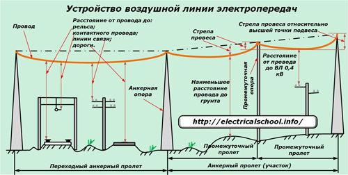
The wires between the supports are never pulled like a string - in a straight line. They always sag a little, being located in the air, taking into account climatic conditions. But at the same time, the safety of their distance to ground objects must be taken into account:
rail surfaces;
contact wires;
transport highways;
wires of communication lines or other overhead lines;
industrial and other facilities.
The sagging of the wire from the taut condition is called. It is assessed in different ways between the supports because the tops of them can be located at the same level or with elevations.
The sag relative to the highest point of support is always greater than that of the lower one.
The dimensions, length and design of each type of overhead transmission line depend on the type of current (alternating or direct) of the electric energy transported through it and the magnitude of its voltage, which can be less than 0.4 kV or reach 1150 kV.
Arrangement of wires of overhead lines
Since the electric current passes only in a closed loop, the consumers are powered by at least two conductors. According to this principle, simple single-phase AC air power lines with a voltage of 220 volts are created. More complex electrical circuits transfer energy in a three or four wire circuit with a solidly insulated or grounded zero.
The diameter and metal for the wire are selected for the design load of each line. The most common materials are aluminum and steel. They can be performed as a single monolithic conductor for low-voltage circuits or woven from multi-wire structures for high-voltage transmission lines.
The internal inter-wire space can be filled with neutral grease, which increases the resistance to heat, or not.
Multi-wire structures made of aluminum wires, which carry a good current, are created with steel cores, which are designed to absorb mechanical tension loads and prevent breakages.

GOST gives a classification of open wires for overhead power lines and defines their marking: M, A, AC, PSO, PS, ACKC, ASKP, ACS, ACO, ACS. In this case, single-wire wires are indicated by the size of the diameter. For example, the abbreviation PSO-5 reads “steel wire. made with one core with a diameter of 5mm. " Stranded wires for power lines use a different marking, including designation with two numbers written through a fraction:
the first is the total cross-sectional area of aluminum conductors in mm sq;
the second is the cross-sectional area of the steel insert (mm sq).
In addition to open metal conductors, wires are increasingly used in modern overhead lines:
self-supporting insulated;
protected by an extruded polymer that protects against short circuits when the phases are swept by the wind or when foreign objects are thrown from the ground.
Overhead lines are gradually replacing old non-insulated structures. They are increasingly used in internal networks, made of copper or aluminum conductors covered with rubber with a protective layer of dielectric fibrous materials or PVC compounds without additional external protection.

To exclude the appearance of a corona discharge of a large length, the wires of VL-330 kV and higher voltage are split into additional flows.

On VL-330, two wires are mounted horizontally, at the 500 kV line they are increased to three and placed at the tops of an equilateral triangle. For overhead lines of 750 and 1150 kV, splitting into 4, 5 or 8 flows, respectively, is used, located at the corners of their own equilateral polygons.
The formation of a "crown" leads not only to energy losses, but also distorts the shape of the sinusoidal oscillation. Therefore, they are struggling with it using constructive methods.
Support device
Supports are usually created to secure the wires of a single electrical circuit. But on parallel sections of two lines, one common support can be used, which is intended for their joint installation. Such designs are called double-circuit.

The material for the manufacture of supports can be:
1. profiled corners of various grades of steel;
2. logs of construction timber impregnated with anti-decay compounds;
3. reinforced concrete structures with reinforced rods.
Support structures made of wood are the cheapest, but even with good impregnation and proper maintenance, they serve no more than 50 ÷ 60 years.

According to the technical design, the supports of overhead lines above 1 kV differ from low-voltage ones in their complexity and the height of the wires fastening.

They are made in the form of elongated prisms or cones with a wide base at the bottom.
Any support structure is calculated for mechanical strength and stability, has a sufficient design margin for existing loads. But it should be borne in mind that during operation, violations of its various elements are possible as a result of corrosion, shock, non-compliance with the installation technology.
This leads to a weakening of the rigidity of a single structure, deformations, and sometimes falls of the supports. Often such cases occur at those moments when people work on the supports, dismantling or pulling wires, creating variable axial forces.
For this reason, the admission of a team of fitters to work at a height from the structure of the supports is carried out after checking them technical condition with an assessment of the quality of its buried part in the ground.
Insulator device
On overhead transmission lines, to separate the current-carrying parts of the electrical circuit between themselves and from the mechanical elements of the support structure, products made of materials with high dielectric properties with ÷ Ohm are used. They are called insulators and are made from:
porcelain (ceramics);
glass;
polymeric materials.

The designs and dimensions of the insulators depend on:
on the magnitude of the dynamic and static loads applied to them;
the values of the effective voltage of the electrical installation;
operating conditions.
The complicated shape of the surface, working under the influence of various atmospheric phenomena, creates an increased path for the flow of a possible electrical discharge.
Insulators installed on overhead lines for fastening wires are divided into two groups:
1.pin;
2. suspended.
Ceramic models
Porcelain or ceramic pin single insulators have found greater application on overhead lines up to 1 kV, although they work on lines up to 35 kV inclusive. But they are used on condition of fastening wires of low cross-sections, creating small tractive forces.
Garlands of suspended porcelain insulators are installed on lines from 35 kV.

The set of a single porcelain suspension insulator includes a dielectric body and a cap made of ductile iron. Both of these parts are held together by a special steel rod. The total number of such elements in a garland is determined by:
the voltage value of the overhead line;
support structures;
peculiarities of equipment operation.
As the line voltage increases, the number of insulators in the string is added. For example, for 35 kV overhead lines, it is enough to install 2 or 3, and for 110 kV, 6 ÷ 7 are already required.
Glass insulators
These designs have a number of advantages over porcelain ones:
the absence of internal defects in the insulating material that affect the formation of leakage currents;
increased strength to twisting forces;
transparency of the structure, which allows visually assessing the condition and monitoring the angle of polarization of the light flux;
lack of signs of aging;
automation of production and smelting.
The disadvantages of glass insulators are:
weak anti-vandal resistance;
low impact strength;
the possibility of damage during transportation and installation from mechanical forces.
Polymer insulators
They have increased mechanical strength and weight reduced by up to 90% compared to ceramic and glass counterparts. TO additional benefits relate:
ease of installation;
greater resistance to pollution from the atmosphere, which, however, does not exclude the need for periodic cleaning of their surface;
hydrophobicity;
good susceptibility to overvoltage;
increased vandal resistance.
The durability of polymeric materials also depends on the operating conditions. In an air environment with increased pollution from industrial enterprises, polymers may exhibit “brittle fracture” phenomena, which consist in a gradual change in the properties of the internal structure under the influence of chemical reactions from pollutants and atmospheric moisture, occurring in combination with electrical processes.
When vandals shoot polymer insulators with shot or bullets, the material is usually not completely destroyed, like glass. Most often, a pellet or bullet flies right through or gets stuck in the body of the skirt. But the dielectric properties are still underestimated and the damaged elements in the garland require replacement.
Therefore, such equipment must be periodically inspected by visual inspection methods. And it is almost impossible to detect such damage without optical instruments.
Overhead line fittings
For fastening insulators on an overhead line support, assembling them into garlands and mounting current-carrying wires to them, special fasteners are produced, which are usually called line fittings.

According to the tasks performed, the fittings are classified into the following groups:
coupling, designed to connect suspension elements in various ways;
tension, which serves for fastening tension clamps to wires and garlands of anchor supports;
supporting, performing the retention of fasteners of wires, loops and assemblies of screens;
protective, designed to preserve the performance of the overhead line equipment when exposed to atmospheric discharges and mechanical vibrations;
connecting, consisting of oval connectors and thermite cartridges;
contact;
spiral;
installation of pin insulators;
installation of self-supporting insulated wires.
Each of the listed groups has a wide assortment of details and requires more careful study. For example, only protective fittings include:
protective horns;
rings and screens;
arresters;
vibration dampers.
Protective horns create a spark gap, divert the emerging electric arc when an insulation overlap occurs and in this way protect the equipment of the overhead line.
Rings and screens divert the arc from the surface of the insulator, improve the voltage distribution over the entire area of the string.
Arresters protect equipment from overvoltage waves generated by lightning strikes. They can be used on the basis of tubular structures made of vinyl plastic or fiber-bakelite tubes with electrodes, or they can be made of valve elements.

Vibration dampers work on ropes and wires to prevent damage from fatigue stresses caused by vibrations and vibrations.
Grounding devices of overhead lines
The need to re-ground the overhead line supports is caused by the requirements of safe operation in the event of emergency modes and lightning overvoltages. The loop resistance of the grounding device should not exceed 30 ohms.
For metal supports, all fasteners and reinforcement must be connected to the PEN conductor, and for reinforced concrete, a combined zero connects all struts and reinforcement of the uprights.
On supports made of wood, metal and reinforced concrete, pins and hooks are not grounded during the installation of self-supporting insulated insulated wire, except in cases where it is necessary to re-ground for overvoltage protection.

The hooks and pins mounted on the support are connected to the ground loop by welding using a steel wire or rod not thinner than 6 mm in diameter with the mandatory presence of an anti-corrosion coating.
On reinforced concrete supports for the grounding descent, metal fittings are used. All contact connections of grounding conductors are welded or clamped in a special bolt fastener.
The supports of overhead power lines with a voltage of 330 kV and above are not grounded due to the complexity of the implementation of technical solutions to ensure a safe magnitude of touch and step voltages. In this case, protective grounding functions are assigned to high-speed line protections.
Air lines are called lines designed for the transmission and distribution of EE through wires located in the open air and supported by supports and insulators. Overhead transmission lines are constructed and operated in a wide variety of climatic conditions and geographic regions, subject to atmospheric influences (wind, ice, rain, temperature changes).
In this regard, overhead lines should be constructed taking into account atmospheric phenomena, air pollution, laying conditions (sparsely populated areas, city territory, enterprises), etc. From the analysis of overhead lines conditions it follows that the materials and structures of the lines must meet a number of requirements: economically acceptable cost , good electrical conductivity and sufficient mechanical strength of materials of wires and cables, their resistance to corrosion, chemical influences; the lines must be electrically and environmentally safe, occupy a minimum area.
Constructive design of overhead lines. The main structural elements of overhead lines are supports, wires, lightning protection cables, insulators and linear fittings.
In terms of the design of the supports, single and double-circuit overhead lines are most common. Up to four circuits can be constructed on a line route. Line route - a strip of land on which the line is being constructed. One circuit of a high-voltage overhead line unites three wires (sets of wires) of a three-phase line, in a low-voltage line - from three to five wires. In general, the structural part of the overhead line (Fig. 3.1) is characterized by the type of supports, span lengths, overall dimensions, phase design, and the number of insulators.
The lengths of the overhead line spans l are chosen for economic reasons, since with an increase in the span length, the sag of the wires increases, it is necessary to increase the height of the supports H so as not to violate the permissible dimension of the line h (Figure 3.1, b), while the number of supports and insulators on the line. Line dimension - the smallest distance from the lowest point of the wire to the ground (water, roadbed) should be such as to ensure the safety of movement of people and vehicles under the line.
This distance depends on the nominal line voltage and the local conditions (populated, uninhabited). The distance between adjacent phases of a line depends mainly on its nominal voltage. The design of the overhead line phase is mainly determined by the number of wires in the phase. If a phase is made with several wires, it is called split. The phases of the high and ultrahigh voltage overhead lines are split. In this case, two wires are used in one phase at 330 (220) kV, three at 500 kV, four to five at 750 kV, eight, eleven at 1150 kV.
Supports of overhead lines. Overhead line supports are structures designed to support wires at the required height above ground, water, or some kind of engineering structure. In addition, in necessary cases, steel earthed cables are suspended on the supports to protect the wires from direct lightning strikes and related overvoltages.
The types and designs of supports are varied. Depending on the purpose and location of overhead lines on the route, they are divided into intermediate and anchor lines. Supports differ in material, design and method of fastening, wire harness. Depending on the material, they are made of wood, reinforced concrete and metal.
Intermediate supports the most simple ones serve to support wires in straight sections of the line. They are the most common; their share is on average 80-90% of the total number of overhead line supports. Wires to them are fastened with the help of supporting (hanging) strings of insulators or pin insulators. In normal operation, intermediate supports are under load mainly from the own weight of wires, cables and insulators, the suspension strings of insulators hang vertically.
Anchor supports installed in places of rigid attachment of wires; they are divided into end, corner, intermediate and special. Anchor supports, designed for the longitudinal and transverse components of the tension of the wires (tension strings of insulators are located horizontally), experience the greatest loads, therefore they are much more complicated and more expensive than intermediate ones; their number on each line should be minimal.
In particular, end and corner supports, installed at the end or at the turn of the line, experience constant tension on wires and cables: one-sided or along the resultant angle of rotation; intermediate anchor, installed on long straight sections, are also calculated for one-sided tension, which can occur when a part of the wires breaks in the span adjacent to the support.
Special supports are of the following types: transitional - for large spans of crossing rivers, gorges; branch lines - for making branches from the main line; transpositional - to change the order of the arrangement of the wires on the support.
Along with the purpose (type), the design of the support is determined by the number of overhead lines and the relative position of the wires (phases). Supports (and lines) are made in a single or double-circuit version, while the wires on the supports can be placed in a triangle, horizontally, a reverse "tree" and a hexagon or "barrel" (Fig. 3.2).
The asymmetrical arrangement of the phase wires in relation to each other (Fig. 3.2) causes the dissimilarity of the inductances and capacities of different phases. To ensure the symmetry of the three-phase system and phase alignment of the reactive parameters on long lines (more than 100 km) with a voltage of 110 kV and above, the wires in the circuit are rearranged (transposed) with the help of appropriate supports.
With a full cycle of transposition, each wire (phase) uniformly along the length of the line takes the position of all three phases on the support in succession (Fig. 3.3).
Wooden supports(Fig. 3.4) are made of pine or larch and are used on lines with voltages up to 110 kV in forest areas, now it is less and less. The main elements of the supports are stepchildren (attachments) 1, posts 2, traverses 3, braces 4, under-transverse beams 6 and crossbars 5. The supports are easy to manufacture, cheap, and easy to transport. Their main drawback is fragility due to rotting wood, despite its treatment with an antiseptic. The use of reinforced concrete stepchildren (attachments) increases the service life of the supports up to 20-25 years.
Reinforced concrete supports (Fig. 3.5) are most widely used on lines with voltage up to 750 kV. They can be free-standing (intermediate) and guyed (anchor). Reinforced concrete supports are more durable than wooden ones, easy to operate, cheaper than metal ones.
Metal (steel) supports (Fig. 3.6) are used on lines with a voltage of 35 kV and above. The main elements include racks 1, traverses 2, cable-resistant 3, guys 4 and foundation 5. They are strong and reliable, but they are quite metal-consuming, occupy a large area, require special reinforced concrete foundations for installation, and during operation must be painted for corrosion protection.
Metal supports are used in cases where it is technically difficult and uneconomical to construct overhead lines on wooden and reinforced concrete supports (crossings over rivers, gorges, making taps from overhead lines, etc.).
Unified metal and reinforced concrete supports have been developed in Russia different types for overhead lines of all voltages, which allows them to be serially produced, to speed up and reduce the cost of the construction of lines.
Overhead lines.
The wires are designed for the transmission of electricity. Along with good electrical conductivity (possibly lower electrical resistance), sufficient mechanical strength and corrosion resistance must satisfy the conditions of economy. For this purpose, wires are used from the cheapest metals - aluminum, steel, special aluminum alloys. Although copper has the highest conductivity, copper wires are not used in new lines due to the significant cost and need for other purposes.
Their use is allowed in contact networks, in the networks of mining enterprises.
On overhead lines, mainly non-insulated (bare) wires are used. By design, the wires can be single- and multi-wire, hollow (Fig. 3.7). Single-wire, mainly steel wires, are used to a limited extent in low-voltage networks. To impart flexibility and greater mechanical strength, wires are made multi-wire from one metal (aluminum or steel) and from two metals (combined) - aluminum and steel. The steel in the wire increases the mechanical strength.
Based on the conditions of mechanical strength, aluminum wires of grades A and AKP (Fig. 3.7) are used on overhead lines with voltages up to 35 kV. Overhead lines 6-35 kV can also be carried out with steel-aluminum wires, and above 35 kV, the lines are mounted exclusively with steel-aluminum wires.
Steel-aluminum wires have braids of aluminum wires around the steel core. The cross-sectional area of the steel part is usually 4-8 times less than the aluminum, but steel takes about 30-40% of the entire mechanical load; such wires are used on lines with long spans and in areas with more severe climatic conditions (with a thicker ice wall).
The grade of steel-aluminum wires indicates the cross-section of the aluminum and steel parts, for example, AC 70/11, as well as data on anti-corrosion protection, for example, ASKS, ASKP - the same wires as AC, but with a core filler (C) or all wires (P) with anti-corrosion grease; ACK - the same wire as AC, but with a core covered with plastic wrap. Corrosion-resistant wires are used in areas where the air is polluted by impurities that have a destructive effect on aluminum and steel. Cross-sectional areas of wires are normalized by the State Standard.
An increase in the diameters of the wires, while the consumption of the conductive material remains unchanged, can be carried out by using wires with a dielectric filler and hollow wires (Fig. 3.7, d, e). This use reduces corona losses (see section 2.2). Hollow wires are used mainly for busbars switchgears 220 kV and above.
Wires made of aluminum alloys (AN - not heat-treated, AZ - heat-treated) have greater mechanical strength than aluminum wires and practically the same electrical conductivity. They are used on overhead lines with voltages above 1 kV in areas with an ice wall thickness of up to 20 mm.
Overhead lines with self-supporting insulated wires with a voltage of 0.38-10 kV are increasingly used. In lines with a voltage of 380/220 V, the wires consist of a non-insulated carrier wire, which is zero, three insulated phase wires, one insulated wire (any phase) of outdoor lighting. Phase insulated wires are wound around the carrying neutral wire (Fig. 3.8).
The carrier wire is made of steel-aluminum, and the phase wires are made of aluminum. The latter are covered with light-resistant heat-stabilized (cross-linked) polyethylene (wire of the APV type). The advantages of overhead lines with insulated wires over lines with bare wires include the absence of insulators on the supports, the maximum use of the height of the support for hanging wires; there is no need to prune trees in the area of the line.
Lightning protection cables along with spark gaps, arresters, voltage limiters and grounding devices serve to protect the line from atmospheric surges(lightning discharges). The cables are suspended above the phase wires (Fig. 3.5) on overhead lines with a voltage of 35 kV and above, depending on the area for thunderstorm activity and the material of the supports, which is regulated by the Rules for Electrical Installations (PUE).
As lightning protection wires, galvanized steel ropes of grades C 35, C 50 and C 70 are usually used, and when using cables for high-frequency communication, steel-aluminum wires. Fastening of cables on all supports of overhead lines with a voltage of 220-750 kV should be performed using an insulator shunted by a spark gap. On 35-110 kV lines, cables are fastened to metal and reinforced concrete intermediate supports without cable insulation.
Overhead line insulators. Insulators are designed to insulate and fix wires. They are made of porcelain and tempered glass - materials with high mechanical and electrical strength and resistance to weathering. An essential advantage of glass insulators is that when damaged, the tempered glass crumbles. This makes it easier to locate damaged insulators on the line.
By design, the method of fastening to the support, insulators are divided into pin and suspended ones. Pin insulators (Fig. 3.9, a, b) are used for lines with voltage up to 10 kV and rarely (for small cross-sections) 35 kV. They are attached to the supports using hooks or pins. Suspended insulators (fig. 3.9, v) are used on overhead lines with a voltage of 35 kV and above. They consist of a porcelain or glass insulating part 1, a ductile iron cap 2, a metal rod 3 and a cement bond 4.
Insulators are assembled into strings (Fig. 3.9, G): supporting on intermediate supports and tension ones - on anchor ones. The number of insulators in a garland depends on the voltage, the type and material of the supports, the pollution of the atmosphere. For example, in the 35 kV line - 3-4 insulators, 220 kV - 12-14; on lines with wooden supports with increased lightning resistance, the number of insulators in the garland is one less than on lines with metal supports; in tension garlands operating in the most severe conditions, 1-2 more insulators are installed than in supporting ones.
Insulators using polymer materials have been developed and are undergoing experimental industrial testing. They are a fiberglass rod-shaped element protected by a coating with fluoroplastic or silicone rubber ribs. Rod insulators, in comparison with suspended ones, have less weight and cost, higher mechanical strength than tempered glass. The main problem is to ensure the possibility of their long-term (more than 30 years) operation.
Linear fittings is intended for fixing wires to insulators and cables to supports and contains the following main elements: clamps, connectors, spacers, etc. (Fig. 3.10).
Supporting clamps are used to suspend and secure overhead lines on intermediate supports with limited rigidity of the termination (Figure 3.10, a). On anchor supports for rigid fastening of wires, tension garlands and tension clamps are used - tension and wedge (Figure 3.10, b, c). Coupling fittings (earrings, ears, staples, rocker arms) are designed for hanging garlands on supports. The supporting garland (Fig. 3.10, d) is fixed on the traverse of the intermediate support using an earring 1 inserted by the other side into the cap of the upper suspension insulator 2. The eyelet 3 is used to attach the garland of the supporting clip 4 to the lower insulator.
Distance spacers (Fig. 3.10, e), installed in the spans of 330 kV and higher lines with split phases, prevent collisions, collisions and twisting of individual phase wires. Connectors are used to connect individual sections of the wire using oval or press connectors (Fig. 3.10, f, g). In oval connectors, wires are either twisted or crimped; in crimped connectors used to connect steel-aluminum wires of large cross-sections, the steel and aluminum parts are crimped separately.
The result of the development of EE transmission technology over long distances is various options for compact power lines, characterized by a smaller distance between phases and, as a consequence, smaller inductive resistances and the width of the line path (Fig. 3.11). When using supports of "female type" (Fig. 3.11, a) reduction of the distance is achieved due to the location of all phase split structures inside the "enclosing portal", or on one side of the pillar of the supports (Fig. 3.11, b). Phase convergence is ensured by means of phase-to-phase isolation spacing. Various versions of compact lines with unconventional layouts of wires of split phases have been proposed (Fig. 3.11, in and).
In addition to reducing the width of the route per unit of transmitted power, compact lines can be created for the transmission of increased power (up to 8-10 GW); such lines cause a lower electric field strength at ground level and have a number of other technical advantages.
The compact lines also include controlled self-compensating lines and controlled lines with an unconventional split phase configuration. They are double-circuit lines in which the phases of the same name of different circuits are shifted in pairs. In this case, stresses are applied to the circuits, shifted by a certain angle. Due to the mode change with the help of special devices of the phase shift angle, control of the parameters of the lines is carried out.
How can you indicate the value of power lines? Is there a precise definition of the wires that carry electricity? There is a precise definition in the intersectoral rules for the technical operation of consumer electrical installations. So, a power transmission line is, firstly, an electric line. Secondly, these are sections of wires that go beyond substations and power plants. Thirdly, the main purpose of power lines is the transmission of electric current over a distance.
According to the same rules of MPTEEP, power transmission lines are divided into overhead and cable ones. But it should be noted that high-frequency signals are also transmitted over power lines, which are used to transmit telemetric data, for dispatching control of various industries, for emergency automation and relay protection signals. According to statistics, 60,000 high-frequency channels today pass through power lines. Let's face it, the indicator is significant.
Overhead transmission lines
Overhead power lines, they are usually denoted by the letters "VL" - these are devices that are located in the open air. That is, the wires themselves are laid through the air and fixed on special fittings (brackets, insulators). Moreover, their installation can be carried out on poles, and on bridges, and along overpasses. It is not necessary to count "overhead lines" those lines that are laid only along high-voltage poles.

What is included in overhead power lines:
- The main thing is the wires.
- Traverses, with the help of which conditions are created for the impossibility of contact of wires with other elements of the supports.
- Insulators.
- The supports themselves.
- Ground loop.
- Lightning arresters.
- Dischargers.
That is, a power line is not just wires and supports, as you can see, it is a rather impressive list of various elements, each of which carries its own specific load. You can also add here fiber optic cables, and ancillary equipment. Of course, if the power transmission line supports high frequency channels communication.
The construction of a power transmission line, as well as its design, plus the design features of the supports are determined by the rules for the installation of electrical installations, that is, PUE, as well as various building rules and regulations, that is, SNiP. In general, the construction of power lines is not an easy and very responsible business. Therefore, their construction is carried out by specialized organizations and companies, where the staff has highly qualified specialists.

Classification of overhead power lines
The air high voltage lines power transmissions are divided into several classes.
By the nature of the current:
- Variable,
- Permanent.
Basically, overhead transmission lines are used to transmit alternating current. The second option is rare. Usually it is used to power the network by contact or communication to provide communication for several power systems, there are other types.
By voltage, overhead power lines are divided according to the nominal value of this indicator. For information, we list them:
- for alternating current: 0.4; 6; ten; 35; 110; 150; 220; 330; 400; 500; 750; 1150 kilovolts (kV);
- for constant, only one type of voltage is used - 400 kV.
At the same time, power lines with voltage up to 1.0 kV are considered to be of the lowest class, from 1.0 to 35 kV - medium, from 110 to 220 kV - high, from 330 to 500 kV - ultra-high, above 750 kV ultra-high. It should be noted that all these groups differ from each other only in the requirements for design conditions and design features. In all other respects, these are ordinary high-voltage power lines.

The voltage of the power lines corresponds to their purpose.
- High-voltage lines with voltage over 500 kV are considered ultra-long-distance, they are intended to connect separate power systems.
- A high-voltage line with a voltage of 220, 330 kV is considered trunk. Their main purpose is to interconnect powerful power plants, separate power systems, as well as power plants within these systems.
- Overhead transmission lines with a voltage of 35-150 kV are installed between consumers (large enterprises or settlements) and distribution points.
- Overhead lines up to 20 kV are used as power lines that directly supply electric current to the consumer.
Classification of power lines by neutral
- Three-phase networks in which the neutral is not grounded. Typically, such a scheme is used in networks with a voltage of 3-35 kV, where small currents flow.
- Three-phase networks in which the neutral is grounded through inductance. This is the so-called resonant-grounded type. In such overhead lines, a voltage of 3-35 kV is used, in which large currents flow.
- Three-phase networks in which the neutral bus is fully grounded (effectively grounded). This mode of neutral operation is used in overhead lines with medium and extra-high voltage. Please note that in such networks it is necessary to use transformers, and not autotransformers, in which the neutral is tightly grounded.
- And, of course, grounded neutral networks. In this mode, overhead lines operate with voltage below 1.0 kV and above 220 kV.
Unfortunately, there is also such a division of power lines, where the operational state of all elements of the power transmission line is taken into account. This is a transmission line in a normal state, where wires, supports and other components are in good condition. Basically, the emphasis is on the quality of wires and cables, they should not be cut off. Emergency condition, where the quality of wires and cables leaves much to be desired. And the installation state, when the repair or replacement of wires, insulators, brackets and other components of the power transmission line is carried out.

Elements of overhead transmission lines
There are always conversations between specialists in which special terms related to power lines are used. For the uninitiated in the intricacies of slang, it is quite difficult to understand this conversation. Therefore, we offer a decoding of these terms.
- The route is the axis of the power transmission line, which runs along the surface of the earth.
- PC - pickets. In fact, these are sections of the power transmission line. Their length depends on the terrain and on the nominal line voltage. Station zero is the beginning of the alignment.
- The construction of a support is indicated by a center sign. This is the center of the support installation.
- Picketage is essentially easy installation pickets.
- Span is the distance between the supports, or rather, between their centers.
- The sag arrow is the delta between the lowest point of the wire sag and the strictly stretched line between the supports.
- The size of the wire is, again, the distance between the lowest point of the sag and the highest point of the engineering structures running under the wires.
- Loop or loop. This is the part of the wire that connects the wires of adjacent spans on the anchor support.
Cable transmission lines
So, we turn to the consideration of such a concept as cable power lines. To begin with, these are not bare wires that are used in overhead power lines, they are cables closed in insulation. Typically, cable transmission lines are several lines installed next to each other in a parallel direction. The length of the cable is sometimes not enough for this, therefore, couplings are installed between the sections. By the way, it is often possible to find oil-filled cable power lines, therefore such networks are often equipped with special low-filling equipment and an alarm system that reacts to the oil pressure inside the cable.
If we talk about the classification of cable lines, then they are identical to the classification of overhead lines. There are distinctive features, but there are not so many of them. Basically, these two categories differ from each other in the way of laying, as well as design features... For example, by the type of laying, cable power lines are divided into underground, underwater and by structures.

The first two positions are clear, but what concerns the position “on structures”?
- Cable tunnels. These are special closed corridors in which the cable is laid along the installed support structures. In such tunnels, you can walk freely, carrying out installation, repair and maintenance of the power line.
- Cable channels. Most often they are buried or partially buried channels. They can be laid in the ground, under the floor base, under the ceilings. These are small channels in which it is impossible to walk. To check or install the cable, you will have to dismantle the ceiling.
- Cable shaft. This is a vertical corridor with a rectangular cross-section. The mine can be a walk-through, that is, with the ability to fit into it for a person, for which it is supplied with a ladder. Or impassable. In this case, you can get to the cable line only by removing one of the walls of the structure.
- Cable floor. This is a technical space, usually 1.8 m high, equipped with floor slabs from below and from above.
- It is also possible to lay cable power lines in the gap between the floor slabs and the floor of the room.
- A cable block is a complex structure consisting of laying pipes and several wells.
- The chamber is an underground structure, closed on top with a reinforced concrete or slab. In such a chamber, the sections of the cable power line are connected by couplings.
- An overpass is a horizontal or inclined structure of an open type. It can be above-ground or above-ground, passable or impassable.
- The gallery is practically the same as the overpass, only of a closed type.
And the last classification in cable power lines is the type of insulation. In principle, there are two main types: solid insulation and liquid insulation. The first includes insulating polymeric braids (polyvinyl chloride, cross-linked polyethylene, ethylene-propylene rubber), as well as other types, for example, oiled paper, rubber-paper braid. Liquid insulators include petroleum oil. There are other types of insulation, for example, special gases or other types of solid materials. But they are rarely used today.

Conclusion on the topic
The variety of power lines is reduced to the classification of two main types: overhead and cable. Both options are used everywhere today, so you should not separate one from the other and give preference to one over the other. Of course, the construction of overhead lines is associated with large investments, because the laying of the route is the installation of mainly metal supports, which have a rather complex structure. This takes into account what network, under what voltage will be laid.