Power line communication has again become a hotly debated topic, at various scientific levels and in the press. This technology has experienced many ups and downs in the past few years. Many articles with conflicting views (conclusions) have been published in special periodicals. Some experts call the transmission of data over power grids a technology that is dying, while others predict a bright future in medium and low voltage networks, for example, in offices and residential buildings.
The technology, which today is called HF communication over power lines, actually encompasses several different and independent directions and applications. On the one hand, this is a narrow-band point-to-point transmission over high voltage overhead lines (35-750 kV), and on the other hand, broadband general network data transmission, (BPL - Broadband Power Line), in medium and low voltage networks (0.4-35 kV ).
Siemens is a pioneer in both directions. The first HF systems on high-voltage lines by Siemens were implemented back in 1926 in Ireland.
The attractiveness of this technology for power supply network operators is that it uses its own power grid infrastructure to transmit information signals. Thus, the technology is not only very economical - there are no operating costs for maintaining communication channels, but also allows power supply companies to be independent from communication service providers, which is especially important in emergency situations, and is even prescribed at the legislative level in many countries. HF communication is a universal technological solution both for enterprises engaged in the transmission and distribution of electricity, and for companies focused on providing services to the population.
HF communication in high voltage networks (35-750 kV)
During the rapid development of information technology (90s), power supply companies in industrialized countries made significant investments in the laying of optical communication lines (FOCL) along high voltage overhead lines in the hope of securing a profitable share of the overheated telecommunications market. At this time, the good old HF technology was buried anew. Then the inflated information technology bubble burst, and sobering up began in many regions. And it was in power grids that the installation of optical lines was suspended for economic reasons, and the technology of HF communication via overhead lines acquired new significance.
As a result of the use of digital technologies in high-voltage networks, new requirements have been formed for HF systems.
At present, data and voice transmission is carried out over fast digital channels, and signals and data of protection systems are transmitted simultaneously (in parallel) over HF lines and digital channels (FOCL), forming a reliable backup (see the next section).
On network branches and long sections of power lines, the use of fiber-optic communication lines is not economically feasible. Here, HF technology offers an economical alternative for the transmission of voice, data and command signals RZ and PA (RZ - relay protection, PA - emergency automation) Figure 1.
Due to the rapid development of power automation systems and digital broadband networks on backbone lines, the requirements for modern systems HF communication.
Today, at the network taps, HF communications are viewed as a system that reliably transmits data from protection systems and provides a transparent user-friendly interface for data and speech from broadband digital networks to the end user with significantly higher bandwidth than conventional analog systems. From a modern point of view, high bandwidth can only be achieved by increasing the bandwidth. What was impossible in the past due to the lack of free frequencies, today is realized thanks to the widespread use of optical lines. Therefore, HF systems are heavily used only on network taps. There are also options when separate sections of the networks are interconnected by fiber-optic communication lines, which allows using the same operating frequencies much more often than in the case of integrated HF communication systems.
In modern digital HF systems, the information density using fast signal processors and digital modulation methods can be increased in comparison with analog systems from 0.3 to 8 bits / s / Hz. Thus, for a bandwidth of 8 kHz in each direction (transmit and receive), 64 kbps can be achieved.
In 2005 Siemens introduced the new PowerLink digital HF communication equipment, confirming its leading position in this field. PowerLink hardware is also certified for use in Russia. With PowerLink, Siemens created a multi-service platform suitable for both analog and digital applications. Figure 2.

The following are the unique features of this system
Optimal use of the allocated frequency: the best HF communication equipment allows data transmission at a speed of 64 kbps or less, while PowerLink has this figure of 76.8 kbps, occupying a bandwidth of 8 kHz.
More speech channels: Another Siemens innovation implemented in the PowerLink system is the ability to transmit 3 analog voice channels at 8 kHz bandwidth instead of 2 channels in conventional equipment.
CCTV: PowerLink is the first RF communications system to transmit a video surveillance signal.
AXC (Automatic Crasstalk Canceller) Automatic Crosstalk Cancellation: Previously, converging transmit and receive bands required sophisticated RF tuning to minimize the effect of the transmitter on its receiver. The patented AXC unit has replaced the complex hybrid tuning and associated module, and the reception and transmission quality has improved.
OSA (Optimized Sub channel Allocation) another patented Siemens solution guarantees optimal resource allocation when configuring services (speech, data, security signaling) in a dedicated frequency band. As a result, the total transmitting capacity is increased by up to 50%.
Increased flexibility: Siemens has implemented an "ease-up!" function to ensure investment security and future use. for a simple and reliable upgrade.
Multifunctional equipment: performing a project on the basis of combined PowerLink equipment, you can forget about the limitations that were in conventional terminals when planning frequencies. With PowerLink you can design an HF communication system with a full range of services (voice, data, relay and PA signals) in the available bandwidth. One PowerLink kit can replace three (3) conventional analog systems Figure 3.

Data transmission of protection systems
HF communication technology now, as before, plays an important role in the field of data transmission of protection systems. On trunk and high-voltage lines with voltages above 330 kV, as a rule, double protection systems are used with different ways measurements (e.g. differential protection and distance protection). For the transmission of data of protection systems, various transmission methods are also used to ensure complete redundancy, including communication channels. Typical communication channels in this case are a combination of digital channels over optical lines for differential protection data and analog HF channels for transmitting distance protection command signals. For transmission of protection signals, RF technology is the most reliable channel. HF communication is a more reliable data transmission channel than others, even optical lines cannot provide such quality after a long time. Outside the trunk lines and at the ends of the network, HF communication often becomes the only channel for the transmission of data from protection systems.
The proven SWT 3000 system from Siemens (Figure 4) is an innovative solution for transmitting RPA commands with the required maximum reliability and at the same time with minimum command transmission time in analog and digital communication networks.

Many years of experience in the field of transmission of protective signals allowed us to create unique system... Thanks to a complex combination of digital filters and digital signal processing systems, it was possible to suppress the influence of impulse noise - the strongest interference in analog communication channels - so that reliable transmission of RP and PA commands is achieved even in difficult real conditions. All known direct shutdown or permissive operation modes with individual timers and coordinated or uncoordinated transmission are supported. The choice of operating modes is carried out using software... Anti-emergency automation functions specific for Russian power grids can be implemented on the same SWT 3000 hardware platform.
When using digital interfaces, the device is identified by the address. In this way, it is possible to prevent accidental connection of other devices over digital networks.
The flexible two-in-one concept allows the SWT 3000 to be used in all available communication channels - copper cables, high voltage lines, optical lines or digital in any combination Figure 5:
- digital + analog on one platform;
- 2 redundant channels in 1 system;
- duplicated power supply in 1 system;
- 2 systems in 1 environment.

As a very cost-effective solution, the SWT 3000 can be integrated into the PowerLink RF system. This configuration provides the possibility of duplicated transmission - analogue on HF technology and digital, for example, over SDH.
HF communication in medium and low voltage networks (distribution networks)
Unlike HF communication via high voltage power lines, in medium and low voltage networks, HF systems are designed for point-to-multipoint operating modes. Also, these systems differ in data transmission speed.
Narrowband systems (digital channels DLC connections) have long been used in power grids for fault locating, remote automation and measurement data transmission. Transfer rates depending on the application from 1.2 kbps to< 100 кбит/с. Передача сигналов в линиях среднего напряжения осуществляется емкостным способом по экрану кабеля среднего напряжения.
Since 2000, Siemens has been successfully offering the DCS3000 digital communication system on the communication systems market. Constant changes in the state of the power grid, caused by frequent switching or connection of various consumer devices, require the implementation of a complex technological task - an integrated productive signal processing system, the implementation of which has become possible only today.
DCS3000 uses high quality OFDM data transmission technology - Orthogonal Frequency Division Multiplexing. Reliable technology ensures automatic adaptation to changes in the transmission network. In this case, the transmitted information in a certain range is optimally modulated on several separate carriers and transmitted in the CENELEC range standardized for power grids (from 9 to 148 kHz). Maintaining the permitted frequency range and transmitting power must overcome changes in the power grid configuration as well as interference typical of the power grid, such as broadband noise, impulse noise and narrowband noise. Additionally, it reliably supports the data transfer function using standard protocols by repeating data packets in the event of a malfunction. The DCS3000 system has been designed for low-speed transmission of data related to power services in the range of 4 kHz to 24 kHz.
Medium voltage networks are usually operated with an open circuit providing two-way access to each transformer station.
The DCS3000 system consists of a modem, a base unit (BU) and inductive or capacitive communication modules. Communication is carried out on a master-slave basis. The main DCS3000 base unit in the transformer substation through the DCS3000 slave base units periodically polls the data of the connected telemetry devices from them and transmits them further to the control panel. DNP3.

Input and output of the information signal is realized before or after switchgears, since the cable shield is grounded only at the bushing ends, using simple inductive connections (CDI). Split ferrite cores can be mounted on the cable shield or on the cable. Depending on specific conditions. It is not necessary to disconnect the medium voltage line during installation.
For other cables or overhead lines, the input is carried out on the phase conductors using capacitive couplings (CDC). For different voltage levels Siemens offers different connections for cable, air distribution and gas insulated systems.
The distribution network can be created with a different topology. The DCS3000 system is ideal for medium voltage networks with linear, tree or star topologies. If there is a screened line with a protective transformer between the two transformer stations, it can be directly connected to the DCS3000. To ensure constant access to the channel, it is desirable to create a logical ring. If this is not possible due to the network topology, then the two lines can be combined into a logical ring using the built-in modem.
The DCS3000 system developed by Siemens is the only communication system successfully implemented in practice in the distribution network. Among other orders, Siemens has built communications systems in Singapore for the Singapore Power Grid and in Macau for CEM Macao. The argument for the implementation of these projects was the opportunity to avoid large expenditures in the construction of a new communication line infrastructure. Siemens has been supplying Singapur PG with communication solutions for the transmission of data over shielded cables for 25 years. In 2000, Siemens was awarded an order for 1,100 DCS3000 systems, which are used by Singapore PG in the 6 kV distribution grid for automation and fault localization. The distribution network is mainly built in a ring pattern.
CEM Macao operates its distribution grid at only one voltage level. Therefore, the requirements here are similar to those for a high voltage network. Special requirements are imposed on the reliability of the communication system being created. Therefore, the DCS3000 system has been expanded with redundant base units and redundant control panel inputs. Medium voltage network is built in the form of a ring and provides data transmission in two directions. More than 1000 DCS3000 systems have ensured reliable operation of the established communications network over the years and serve as proof of its effectiveness.
In Egypt, transformer stations were not equipped with remote service input channels. Creating new connections was expensive. There was a fundamental possibility of using radio modems, but the number of available frequencies for individual transformer stations was limited and it was impossible to avoid significant additional operating costs. An alternative solution was the DCS3000 system. Data from remote telemechanics terminals were transmitted to the transformer substation. The top-level telemechanics system collected data and transmitted it via radio communication to data concentrators, from where they, in turn, were transmitted via the existing remote control lines to the control center. For two projects Siemens has supplied over 850 DCS3000 systems to MEEDCO (10 kV) and DELTA (6 kV).

Broadband systems(Broadband Power Line BPL) After years of experimental installations in different countries world and numerous commercial projects, the second generation of BPL technology has evolved so much that it has become an attractive alternative for other broadband access networks.
In low voltage networks, BPL gives the provider the opportunity to provide broadband access to triple play services at the last mile:
- high-speed internet access;
- IP telephony;
- video.
Users can use these offered services by connecting to any electrical outlet. Organization in the house is also possible local network for connecting computers and peripheral devices without laying additional cables.
For utilities, the BPL is not currently being considered. The only service in use today - remote meter reading - uses cost-effective solutions such as GSM or slow DLC systems. However, when combined with broadband services, BPL becomes attractive for meter reading as well. Thus, "triple play" turns into a "quad play" (Figure 8).

In the medium voltage network, the BPL is used for broadband services as a transport channel to the nearest access point of the provider. For utilities - at present, remote reading of meter readings of ASKUE devices - there are enough narrow-band systems operating in the range from 9 to 148 kHz allocated by CENELEC for utilities. Of course, mixed service medium voltage BPL systems (“shared channel”) can be used for both the provider and the utility.
The value of BPL is growing, as evidenced by the increase in investment in this type of communication of utilities, providers and industry. In the past, the main active players in the BPL market were predominantly small enterprises specializing exclusively in this technology, but today large groups such as Schneider Electric, Misubishi Electric, Motorola and Siemens are entering this market. This is another sign of the growing importance of this technology. However, a significant breakthrough has not yet occurred for two key reasons:
1. Lack of standardization
The BPL uses a frequency range from 2 to 40 MHz (up to 80 MHz in the US), which is used by various shortwave services, government agencies and radio amateurs. It was radio amateurs who launched a campaign against BPL in some European countries - and this topic is actively discussed. International standardization institutions, for example, ETSI, CENELEC, IEEE, in special working groups develop a standard regulating the use of BPL in medium and low voltage networks and distribution networks
in buildings and guaranteeing coexistence with other services.
2. Cost and business model
The cost of a Powerline infrastructure with modems, interconnect equipment and repeaters is still high compared to, for example, DSL technology. The high cost, on the one hand, is explained by the small production volumes, and on the other hand, by the early stage of development of this technology. When using broadband services, BPL technology must be competitive with DSL in both performance and cost.

In terms of the business model, the role of utilities in creating value can vary greatly, from the sale of the right to use to the full provision of the service provider. The main difference between the various models is the participation rate of utilities.
Communication technology trends
In public telecommunications networks today, over 90% of data traffic goes through SDH / SONET. These fixed-line circuits are becoming uneconomical today as they remain operational even when not in use. In addition, market growth has shifted markedly from voice applications (TDM) to data communications (packet orientation). The transition from separate networks of mobile and wire communications, LAN and WAN to a single integrated IP-network is carried out in several stages, taking into account the existing network. In the first phase, packet-oriented data traffic is transmitted in virtual packets of the existing SDH network. This is called PoS ("Packet over SDH") or EoS ("Ethernet over SDH") with reduced modularity and therefore lower efficiency of the allocated bandwidth. The next transition from TDM to IP is offered by today's NG SDH (Next Generation SDH) systems with a multiservice platform that is already optimized for packet-oriented applications GFP (General Synchronization Procedure), LCAS (Line Bandwidth Adjustment Scheme), RPR (Flexible Packet Rings) and other applications in the SDH environment.
This evolution in communication technology has also influenced the structure of power grid management. Traditionally, communication between control centers and substations for supervisory control and data acquisition systems has been based on serial protocols and dedicated channels that provide short signal transit times and are always available. Of course, dedicated circuits do not provide the flexibility required to operate a modern power grid. So the trend towards TCP / IP (Transmission Control Protocol / Internet Protocol) has come in handy. The main drivers for the transition from serial to IP in supervisory control and data acquisition systems are:
- the proliferation of optical systems provides an increase in bandwidth and resistance to electrical interference;
- TCP / IP and related technologies have become the de facto standard for data networks;
- the emergence of standardized technologies that ensure the required quality of functioning of networks with the TCP / IP protocol (QoS quality of service).
These technologies have the potential to allay technical concerns about reliability and the ability to provide fast response times for supervisory control and data acquisition applications.
This transition to a TCP / IP network makes it possible to integrate supervisory control and data collection network management into overall network management.
In this case, the configuration change can be carried out by downloading from the central control unit instead of the time-consuming updating of the firmware of the corresponding substations. Standards for IP-based telemechanical systems protocols are being developed by the global community and have already been released for communication in substations (IEC61850) Figure 10.

Standards for communication between substations and the control center and between the substations themselves are still under development. At the same time, the transfer of voice applications from TDM to VoIP, which will significantly simplify cable connections at substations, since all devices and IP telephony use one local network.

In older distribution grids, communication connections were rare because the level of automation was low and meter data collection was rare. The evolution of power grids in the future will require communication channels at this very level. Constantly growing consumption in megacities, scarcity of raw materials, an increase in the share of renewable energy sources, generation of electricity in the immediate vicinity of the consumer ("distributed generation") and reliable distribution of electricity with low losses are the main factors determining the management of tomorrow's grids. In the future, communication in AMR will be used not only for reading consumption data, but also as a two-way communication channel for flexible tariff formation, connecting gas, water and heat supply systems, transferring bills and providing additional services, for example, burglar alarms. Ubiquitous Ethernet connectivity and sufficient bandwidth from the control system to the customer are essential to manage the operation of future networks.
Conclusion
The integration of telecommunications services into power grids will require close integration of various technologies. Several types of communication will be used in one power grid, depending on the topology and requirements.
HF communication systems over power lines can be the solution to these problems. The evolution of IP support, especially for HF over high voltage transmission lines, provides significant increases in throughput. Siemens is also contributing to this development - technologies are already being developed to increase the bandwidth and therefore the transmission speed up to 256 kbps. BPL technology is an excellent platform for communication in future medium and low voltage networks to provide consumers with all new services. Future BPL systems from Siemens offer a single hardware platform for both narrowband (CENELEC) and broadband applications. In the next generation of energy networks, HF will take a firm foothold and be an ideal complement to optical and wireless broadband systems.
Siemens is following this trend and is one of the few global manufacturers in both RF and communications networks ready to offer a single integrated solution.
Literature:
- Energie Spektrum, 04/2005: S. Schlattmann, R. Stoklasek; Digital-Revival von PowerLine.
- PEI 01/2004: S. Green; Communication Innovation. Asian Electricity 02/2004: Powerline Carrier for HV Networtk.
- Middle East Electricity, Feb. 2003: J. Buerger: Transmission Possible.
- Die Welt, April 2001; J. Buerger: Daten vom Netz ubers Netz.
- VDI Nachrichten 41; Oktober; 2000 M. Wohlgenannt: Stromnetz ubertrugt Daten zur eigenen Steuerung. Elektrie Berlin 54 (2000) 5-6; J. Buerger, G. Kling, S. Schlattmann: Power Line Communication-Datenubertragung auf dem Stromverteilnetz.
- EV Report, Marz 2000: J. Buerger, G. Kling, S. Schlattmann: Kommunikationsruckrat fur Verteilnetze.
- ETZ 5/2000; G. Kling: Power Line Communication Technik fur den deregulierten Markt.
Karl Dietrich, Siemens AG,
Department of Power Transmission and Distribution PTD,
division of EA4 CS.
Translation: E. A. Malyutin.
Equipment high frequency communication with digital signal processing (AVC) was developed by RADIS Ltd, Zelenograd (Moscow) in accordance with the terms of reference approved by the Central Dispatch Office of the UES of Russia *. AVC was accepted and recommended for production by the interdepartmental commission of JSC FGC UES in July 2003, it has a certificate from the State Standard of Russia. The equipment has been manufactured by RADIS Ltd since 2004.
* At present JSC SO-CDU UES.
Purpose and capabilities
The AVC is designed to organize 1, 2, 3 or 4 channels of telephone communication, telemechanical information and data transmission over a 35-500 kV power transmission line between the dispatch center of a district or an enterprise of electrical networks and substations or any objects necessary for dispatch and technological control in power systems ...
In each channel, telephone communication can be organized with the possibility of transmitting telemechanical information in the supra-tone spectrum by built-in or external modems, or data transmission using the built-in or external user modem.
AVC modifications
Combined option
terminal AVC-S

Execution
The AVC widely uses methods and means of digital signal processing, which makes it possible to ensure the accuracy, stability, manufacturability and high reliability of the equipment. The AM OBP modulator / demodulator, a transmultiplexer, adaptive equalizers, built-in telemechanics modems and service control signal modems included in the AVC are made using signal processors, FPGAs and microcontrollers, and the telephone automation and control unit are implemented on the basis of microcontrollers. The Analytic STF / CF519C modem is used as a built-in modem for data transmission in the channel.
Specifications
| Number of channels | 4, 3, 2 or 1 |
| Working frequency range | 36-1000 kHz |
| Nominal frequency band of one direction of transmission (reception): | |
| - for one-channel |
4 kHz |
| - for two-channel | 8 kHz |
| - for three-channel | 12 kHz |
| 16 kHz | |
| Minimum frequency separation between the edges of the nominal transmit and receive bands: | |
| - for one- and two-channel | 8 kHz (in the range up to 500 kHz) |
| - for three-channel | 12 kHz (in the range up to 500 kHz) |
| - for four-channel equipment | 16 kHz (in the range up to 500 kHz) |
| - one-, two-, three- and four-channel equipment | 16 kHz (in the range from 500 to 1000 kHz) |
| Maximum peak transmitter power | 40 watts |
| Receiver sensitivity | -25 dBm |
| Selectivity of the receiving path | meets the requirements of IEC 495 |
| AGC adjustment range in the receiver | 40 dBA |
| The number of built-in telemechanics modems (baud rate 200, 600 baud) in each channel | |
| - at a speed of 200 Baud | 2 |
| - at a speed of 600 Baud | 1 |
| The number of connected external telemechanics modems in each channel | No more than 2 |
| Number of built-in data modems (speed up to 24.4 kbps) |
Up to 4 |
| The number of connected external modems for data transmission | Up to 4 |
| Rated impedance for RF output | |
| - unbalanced | 75 Ohm |
| - balanced | 150 Ohm |
| Operating temperature range | 0 ... + 45 ° С |
| Nutrition | 220 V, 50 Hz |
Note: with a balanced output, the midpoint can be connected to ground directly or through a 75 ohm 10W resistor.
Short descriptionTerminal AVTs-NCH is installed at the dispatching point, and AVTs-VCh - at the reference or nodal substation. Communication between them is carried out via two telephone pairs. Frequency bands occupied by each communication channel:
The overlapped attenuation between the AVC-LF and AVC-HF terminals is not more than 20 dB at the maximum channel frequency (the characteristic impedance of the communication line is 150 Ohm).
The effective bandwidth of each channel in the AVC is 0.3-3.4 kHz, and it can be used:
Remote control signals are transmitted using built-in modems (two at 200 Baud, medium frequencies 2.72 and 3.22 kHz, or one at 600 Baud, medium frequency 3 kHz) or external user modems.
Data transmission is carried out using the built-in STF / CF519C modem (depending on the line parameters, the speed can reach 24.4 kbps) or an external user modem. This makes it possible to organize up to 4 channels of machine-to-machine communication.
The AVC-LF (AVC-S) receive path provides for a semi-automatic correction of the frequency response of the residual attenuation of each channel.
Each telephone channel of AVC has the ability to turn on a compander.
|
|
AVTs-NCH (AVTs-S) contains built-in devices for automatic connection of subscribers (automatic telephone systems), which allow connecting: |
| If the channel is used for data transmission, the telephone automation cell is replaced by the cell of the built-in STF / CF519C modems. |
|


AVTs-LF and AVTs-S have a control unit that, using a service modem of each channel (transmission rate 100 Baud, average frequency 3.6 kHz), transfers commands and continuously monitors the presence of communication between the local and remote terminals. If communication is lost, a sound signal is generated and the contacts of the external alarm relay are closed. In the non-volatile memory of the unit, an event log is kept (switching on / off and readiness of the equipment, “loss” of the communication channel, etc.) for 512 entries.
The required AVC modes are set using a remote control panel or an external computer connected via the RS-232 interface to the control unit. The control panel allows you to take a diagram of the levels and characteristics of the residual attenuation of the channel, perform the necessary correction of the frequency response and evaluate the level of characteristic distortions of the built-in telemechanics modems.
The operating frequency of the equipment can be tuned by the user within one of the sub-bands: 36-125, 125-500 and 500-1000 kHz. Tuning step - 1 kHz .
Communication channel organization schemes
In addition to the direct communication channel (“point-to-point”), more complex schemes for organizing communication channels (“star” type) are possible between the AVC semi-sets. Thus, a two-channel dispatching half-set allows organizing communication with two single-channel half-sets installed in controlled points, and a four-channel one - with two two-channel or four single-channel half-sets.

Other similar configurations of communication channels are possible. With the help of an additional AVC-HF terminal, the equipment provides the organization of four-wire transfer without channel selection.

In addition, the following options can be provided:
|
With the help of only the AVTs-HF terminal, work is organized in conjunction with an external modem with a 4, 8, 12 or 16 kHz band in the nominal frequency range from 0 to 80 kHz, which makes it possible to create digital high-frequency communication complexes. For example, on the basis of the AVTs-VCh terminal and the Zelaks M-ASP-PG-LEP modems, it is possible to organize communication with a data transfer rate of up to 80 kbit / s in a 12 kHz band and up to 24 kbit / s in a 4 kHz band. |
|
|
In the nominal bandwidth of 16 kHz, the AVC organizes two channels, namely the 1st one with a bandwidth of 4 kHz for telephone connection and the second with a 12 kHz bandwidth for data transmission by user equipment. |
|
|
The work of up to four single-channel subscriber semi-sets of the AVC is organized at controlled points with a single-channel dispatching semi-set of the AVC. With a telephone channel bandwidth of 0.3-2.4 kHz, the equipment will provide one duplex communication channel for the exchange of telemechanical information at a rate of 100 Baud between the dispatcher and each semi-set at the controlled point. When using external modems with a speed of more than 100 Baud, only cyclical or sporadic exchange of telemechanical information between the dispatching and subscriber semi-sets is possible. |
Equipment weight and dimensions
Name |
Depth mm |
Height, mm |
||
Installation
The equipment can be installed on a rack (up to several vertical rows), in a 19 ”rack, or mounted on a wall. All cables for external connections are connected from the front. An intermediate terminal block for connecting cables is available on request.
Environmental conditions
AVC is designed for continuous round-the-clock work in stationary conditions, in closed rooms without constant attendants at temperatures from 0 to + 45C O and relative humidity up to 85%. The efficiency of the equipment is maintained at ambient temperatures up to -25C O.
To transfer information between protections and automation at the ends high voltage line a channel created for high-frequency currents in a phase-to-earth connection is used.
As part of the path, one phase of the operating overhead line is included, which is connected to the ground through the coupling capacitors at the substations to create a closed loop for HF currents.
Most often, two remote phases "A" and "C" are used on the line for transmission of frequency commands 1 from substation through one of them, and reception at frequency 2 through the second.
The structure and purpose of the HF communication channel... Each substation is equipped with transmitters and receivers of high-frequency signals. In this case, the modern equipment of HF transceivers is made on the microprocessor base of ETL640 v.03.32 terminals by ABB.
For processing signals at each frequency, its own transceiver is manufactured. Therefore, one substation requires 2 sets of terminals configured to simultaneously receive and transmit signals on different phases of the overhead line.
![]()
The connection of the HF transceiver to the overhead line is handled by special equipment that separates high voltage from low-current equipment and creates a highway for transmitting HF signals. It is completed with:
High-voltage coupling capacitor (CS);
- connection filter (FP);
- high-frequency minelayer (VZ);
- HF cable.
The purpose of the high-voltage coupling capacitor is to reliably isolate the power transported along the overhead line with an industrial frequency from the ground and to pass high-frequency currents through itself.

In the photograph of the line under consideration, there are 3 capacitors with phase converters in each phase. They are used to communicate with far-end equipment in order to:
1. Transmission of RZ and PA commands;
2. Reception of RZ and PA commands;
3. Work of HF equipment of the communication service.
 To separate the high-frequency signal from the high-voltage equipment of the substation, a high-frequency trap is mounted in the phase conductor of the high-voltage overhead line. which limits the amount of RF signal loss through parallel circuits.
Currents pass well through it industrial frequency and high-frequency ones are not skipped. VZ consists of a reactor (power coil), which passes the operating current of the line, and adjustment elements connected in parallel with the reactor.
To match the parameters of the input impedances of the HF cable and line, a connection filter is used, which is performed by a model of an air transformer with taps from the windings, which allow making the necessary adjustments. The RF cable connects the coupling filter to the transceiver.
High frequency transceivers (ETL640), purpose... Transceivers of ETL640 type (PRM / PRD) are designed to transmit and receive RF signals in the form of commands generated by relay protection (RP) and emergency control equipment (PA) to the opposite end of the overhead line.
Checking the serviceability of the HF channel... The complex equipment of the HF transmission path is located at distances of hundreds of kilometers and requires monitoring and maintaining its integrity. ETL640 transceivers at the ends of the overhead line constantly in normal operation exchange (transmit / receive) signals of the control frequency.
When the signal decreases in magnitude or changes in its frequency beyond the permissible limits, a malfunction alarm is triggered. After the restoration of operability, the transceiver in automatic mode returns to normal operation.
Signal exchange... Signals are transmitted and received at selected frequencies, for example:
Complex on phase “A”: Тх: 470 + 4 kHz, Rx: 474 + 4 kHz;
- complex on phase “C”: Тх: 502 + 4 kHz, Rx: 506 + 4 kHz.
ETL640 equipment is designed for round-the-clock continuous operation in heated substations.
Reception and transmission of commands... Terminals No. 1 and No. 2 of ETL640 complexes receive and transmit 16 commands each from RZ and PA.
ETL640 Transceiver Commands... Typical commands of the transceiver of any ETL640 complex can be as follows:
![]() 1. Disconnection of 3 phases of a 330 kV overhead line from the far end of the overhead line without control, with the prohibition of TAPV and start-up from the breaker failure or ZNR complex No.… REL-670;
1. Disconnection of 3 phases of a 330 kV overhead line from the far end of the overhead line without control, with the prohibition of TAPV and start-up from the breaker failure or ZNR complex No.… REL-670;
2. Disconnection of 3 phases of the 330 kV overhead line from the far end of the overhead line with control by measuring devices Z3 DZ and the 3rd stage of NTZNP complex No.… REL670 protection without prohibiting TAPV and starting from the factor of 3-phase shutdown of the complex No.… REL protections;
3. Teleacceleration of DZ with action on one or 3-phase shutdown of 330 kV overhead line from the far end of the overhead line, with control of the parameters of stage Z3 DZ of complex No. ... protection REL670 with OAPV / TAPV and starting from stage Z3 DZ of complex No. ... 670;
4. Teleacceleration of NTZNP with action on one or 3-phase shutdown of 330 kV overhead line from the far end of the overhead line with control of parameters of stage Z3 of NTZNP of complex No.… protection REL670 with OAPV / TAPV and start-up from a measuring device of 3rd stage NTZNP of complex No.… protection REL670 ;
5. Fixing the disconnection of the line from its side of the overhead line and acting in the AFOL logic circuit of the complex No.… protection of relay protection and automation. Start from the output relay of the AFOL logic circuit of complex No.… protection of relay protection and automation devices when the line is disconnected from its side;
6. III stage of OH, acting on launch:
- 5th command of AKAP prd 232 kHz overhead line No. ...;
- 2nd command of AKPA prd 286 kHz overhead line No. ...;
- 4th team ANKA prd 342 kHz overhead line No.….
7. Fixation of the connection of the line from its side and action in the AFOL logic circuit of the complex № ... protection of relay protection and automation equipment of overhead lines with start from the output relay of the AFOL logic circuit of the complex №… protection of relay protection and automation equipment VL-330 when switched on from its side;
8. Start-up from the 1st stage of the SAPAH scheme ... with start-up:
- 6th team ANKA prd 348 kHz overhead line No. ...;
- 4th command AKAP prd 122 kHz overhead line No.….
9. 3rd stage of load shedding with action ...
Each team is formed for the specific conditions of the overhead line, taking into account its configuration in the electrical network and operating conditions. RF output relays and switching devices are located in a separate cabinet.
Signaling circuits overhead lines... Terminal alarms. On the front panel of the terminals there are 3 LEDs reflecting the state of the REL670 device itself and 15 LEDs indicating the operation of protections, malfunctions and the state of the operational switches.
The LEDs of the terminals REL670 (protection of the 1st and 2nd complexes) and REC670 (automatic equipment and CBFP of the 1st and 2nd complexes B1 and B2) of the first six numbers are colored red. LEDs numbered 7 to 15 are yellow.

LEDs for status indication. 3 LED indicators “Ready”, “Start” and “Trip” are inserted above the LCD block of the REС670 and REL670 terminals. They light up in different colors to indicate different information. The green light indicates:
The devices work - with a steady glow;
- internal damage - by flashing;
- no power supply of the operating current - by dimming the color.
The yellow indicator color means:
Emergency recorder start-up - steady glow ;;
- finding the terminal in test mode - accompanied by blinking.
The red color of the indicator indicates the issuance of the emergency shutdown command (steady light).

LED signaling table for REС670 terminal

Resetting and testing alarms... Resetting the alarm, counters for the reception and transmission of high-frequency commands and information on the DZ and NTZNP zones for the terminal is made by pressing the SB1 button (alarm reset) on the front side of the cabinet.
To test the LEDs of the REL670 (REС670) terminals, press and hold the SB1 button for more than 5 seconds.
General panel light signaling... On the front side of the REС670 cabinets there are lamps:
- HLW - works of automatic reclosure, ZNF, UROV;
- HLR2 - malfunction of the automation and breaker failure protection V-1 or V-2.
On the front side of REL670 cabinets there are lamps:
- HLW - protection works;
- HLR1 - protection complex disabled;
- HLR2 - malfunction of protection complexes.
On the front side of ETL cabinets there are alarm lamps:
- HLW1 - ETL malfunction of the 1st complex;
- HLW2 - ETL malfunction of the 2nd complex.
Equipment development prospects overhead power lines ... Time-tested air circuit breakers for high voltage transmission lines are gradually being replaced by modern gas-insulated designs that do not require permanent job powerful compressor stations to maintain air pressure in tanks and air lines.
Bulky analogue relay protection and automation devices for high-voltage equipment, requiring close attention from the maintenance personnel, are being replaced by new microprocessor terminals.
Page 16 of 21
The design of the power transmission line, determined by its main purpose - the transmission of electrical energy over a distance, makes it possible to use it for the transmission of information. High level operation and high mechanical strength of the lines ensure the reliability of communication channels, close to the reliability of channels over cable lines communication. At the same time, when implementing communication channels over overhead lines for transmitting information, it is necessary to take into account the features of the lines that make it difficult to use them for communication purposes. Such a feature is, for example, the presence of substation equipment at the ends of the lines, which can be represented as a chain of reactance and active resistance connected in series over a wide range. These resistances form a connection between the overhead lines through the substation buses, which leads to an increase in the communication path. Therefore, to reduce the influence between the channels and attenuation, using special barriers, they block the paths of high-frequency currents towards the substations.
The attenuation of the branches from the overhead line also significantly increases. These and other features of the lines require the implementation of a number of measures to create conditions for the transmission of information.
The device of HF channels over 6-10 kV distribution networks is fraught with significant difficulties due to the specifics of the construction of networks of these voltages. On the sections of main lines 6-10 kV between neighboring switching points there are a large number of taps, the lines are sectioned by disconnectors and switches, the primary switching circuits of networks often change, including automatically, due to the greater damage to the lines of these voltages, their reliability is lower than B71 35 kV and above. Signal transmission in distribution networks depends on many factors affecting signal attenuation: the length and number of taps, line wire material, load, etc. The load can vary widely. At the same time, the disconnection of individual taps, as studies show, sometimes not only does not reduce the attenuation, but, on the contrary, increases it due to the violation of mutual compensation of attenuation between adjacent taps. Therefore, even small channels have significant attenuation and are unstable. The operation of the channels is also adversely affected by damage to the insulators, poor-quality wire connection and the unsatisfactory condition of the contacts of the switching equipment. These defects are sources of interference, commensurate with the level of the transmitted signal, which can cause the channel to stop working and damage the equipment. The presence of sectioning devices on the lines leads to a complete cessation of the operation of the HF channel in the event of their disconnection and grounding of one of the sections of the line. The noted disadvantages significantly limit, although they do not exclude, the use of 6-10 kV lines for organizing HF channels. Still, it should be noted that HF communication over distribution networks has not received widespread use at the present time.
By designation, high-frequency communication channels over power transmission lines are divided into four groups: dispatch communication channels, technological, special and linear operational communication channels.
Without dwelling in detail on the use and purpose of each group of channels, we note that for dispatching and technological telephone communication channels, mainly the tone frequency band of 300-3400 Hz is used.<300-2300). Верхняя часть тонального спектра (2400-3400 Гц) не пользуется для передачи сигналов телеинформации. Современная комбинированная аппаратура позволяет организовать в этом спектре до четырех независимых узкополосных каналов телеииформации.
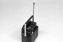
Line-operational communication channels are used to organize communication between the dispatcher and the repair crews working on the route of an extended power transmission line or substations, when there is no constant communication with them. For these channels, simplified transportable and portable telephone equipment is used.
According to the degree of complexity, HF channels are divided into simple and complex. Channels consisting of only two sets of RF terminal equipment are called simple. Complex channels include intermediate amplifiers or several sets of terminal equipment (at the same frequencies).
Equipment for high-frequency communication channels over overhead lines.
The connection of the communication equipment to the wires of the power transmission line is carried out using special devices, the so-called equipment for connecting and processing the line, consisting of a coupling capacitor, a trap and protection elements.
Rice. 21. Scheme of a high-frequency communication channel for overhead lines
In fig. 21 shows a diagram of the formation of a communication channel over the overhead line. Signal transmission by high-frequency currents It is carried out by the transmitters of the compaction equipment J, located at both ends of the overhead line at substations A and B.
Here, in the composition of the compaction equipment 1, there are receivers that receive modulated RF currents and convert them. To ensure the transmission of signal energy by HF currents through the wires, it is sufficient to process one wire at each end of the line using a trap 5, a coupling capacitor 4 and a connection filter 3, which is connected to the sealing equipment 1 using an HF cable 2. To ensure the safety of personnel working on the connection filter when the RF channel is operating, the grounding knife is used 6.
Connecting high-frequency equipment according to the diagram in Fig. 21 is called phase-to-earth. Such a scheme can be used to form single-channel and multi-channel information transmission systems. Other connection schemes are also used.
If it is necessary to connect the equipment installed on the line route to the power transmission line (mobile telephone equipment of repair teams, equipment of a remotely controlled VHF radio station, etc.), as a rule, antenna connection devices are used. Sections of insulated wire of a certain length or sections of a lightning protection cable are used as an antenna.
A high-frequency (linear) trap has a high resistance for the operating frequency of the channel and serves to block the path of these currents, reducing their leakage towards the substation. In the absence of a suppressor, the channel attenuation may increase, since the small input impedance of the substation shunts the RF channel. The trap consists of a power coil (reactor), a setting element and a protection device. The power coil is the main element of the minelayer. It must withstand the maximum operating line currents and short-circuit currents. The power coil is made of coiled copper or aluminum wires of the appropriate cross-section, wound on wood-laminated plastic (delta-wood) or fiberglass rails. The ends of the rails are fixed on metal crosspieces. A setting element with protective arresters is attached to the upper crosspiece. The tuning element is used to obtain a relatively high resistance of the trap at one or several frequencies or frequency bands.
The tuning element consists of capacitors, inductors and resistors and is connected in parallel
power coil. The power coil and setting element of the trap are exposed to atmospheric and switching overvoltages and short circuits. The role of overvoltage protection, as a rule, is performed by a valve arrester consisting of a spark gap and a non-linear power resistor.
In electrical networks of 6-220 kV, minelayers VZ-600-0.25 and KZ-500, as well as minelayers with a steel core of the VChZS-100 and VChZS-100V types, differing from each other in rated current and inductance, stability and geometric parameters power coil, as well as the type of setting element and its protection.
The arresters cut into the phase conductor of the power line between the line disconnector and the coupling capacitor. High-frequency traps can be mounted suspended, on supporting structures, including coupling capacitors.
Coupling capacitors are used to connect HF equipment to the overhead line, while the power frequency leakage currents are discharged through the coupling capacitor to ground, bypassing the high frequency equipment. Coupling capacitors are designed for phase voltage (in a network with a grounded neutral) and for a line voltage (in a network with an isolated neutral). In our country, two types of coupling capacitors are produced: СМР (communication, oil-filled, with an expander) and SMM (communication, oil-filled, in a metal case). For different voltages, capacitors are assembled from individual elements connected in series. Coupling capacitors can be installed on reinforced concrete or metal supports with a height of about 3 m. To isolate the lower element of the СМР type capacitor from the support body, special porcelain supports with a circular cross-section are used.
The coupling filter serves as a link between the coupling capacitor and the RF equipment, separating the high voltage line and the low current setting, which is the sealing equipment. The connection filter thus ensures the safety of personnel and protection of the equipment from high voltage, since when the lower plate of the coupling capacitor is grounded, a path is formed for leakage currents of industrial frequency. With the help of the connection filter, the wave impedances of the line and the high-frequency cable are matched, as well as the compensation of the reactance of the coupling capacitor in a given frequency band. Connection filters are made according to transformer and autotransformer circuits and together with coupling capacitors form band-pass filters.
The most widespread in the organization of high-frequency communication channels through the power transmission lines of the enterprise is the connection filter of the OFP-4 type (see Fig. 19). The filter is enclosed in a steel welded casing with a bushing for connecting a coupling capacitor and a cable funnel for entering an RF cable. An arrester is mounted on the wall of the housing, which has an elongated pin for connecting the grounding bus and is designed to protect the connection filter elements from overvoltage. The filter is designed for connecting RF equipment according to the phase-to-ground scheme, complete with coupling capacitors with a capacity of 1100 and 2200 pF. The filter is installed, as a rule, on the support of the coupling capacitor and is bolted to the support at a height of 1.6-1.8 m from the ground level.
As noted, all switchings in the connection filter circuits are performed with the grounding knife turned on, which serves to ground the lower plate of the coupling capacitor during the work of personnel. A single-pole disconnector for a voltage of 6-10 kV is used as a grounding knife. Operations with the grounding knife are carried out using an insulating rod. Some types of connection filters have an earthing knife mounted inside the housing. For safety reasons, a freestanding earthing blade must be installed in this case.
The high-frequency cable is used for electrical connection of the connection filter (see Fig. 21) with the transceiver equipment. When connecting the equipment to the line according to the phase - earth scheme, coaxial cables are used. The most common is a high-frequency coaxial cable of the RK-75 brand, the inner conductor (single-core or multi-core) of which is separated from the outer braid by high-frequency dielectric insulation. The outer braided shield serves as a return conductor. The outer conductor is enclosed in a protective insulating sheath.
The high-frequency characteristics of the RK-75 cable, like ordinary communication cables, are determined by the same parameters: wave impedance, kilometric attenuation and the speed of propagation of electromagnetic waves.
Reliable operation of HF channels on overhead lines is ensured by high-quality and regular performance of scheduled preventive work, which provides for a whole range of work on the equipment of HF communication channels over overhead lines. To perform preventive measurements, the channels are taken out of service. Preventive maintenance includes scheduled checks of equipment and channels, the frequency of which is determined by the state of the equipment, the quality of maintenance, taking into account preventive maintenance, and is set at least once every 3 years. Unscheduled channel checks are performed when the RF path is changed, equipment is damaged, and when the channel is unreliable due to violation of the regulated parameters.
MOSCOW, May 11 - RIA Novosti. In the book by Vladimir Bogomolov "The Moment of Truth" about the Great Patriotic War, "notes on HF" and HF communication devices are often mentioned, through which the Supreme Commander-in-Chief communicated with the headquarters. The communication was secure and it was impossible to eavesdrop on it without the use of special means. What kind of connection was that?
HF communication, kremlyovka, automatic telephone exchange-1 is a system of secure communication channels, which to this day ensures the stability and confidentiality of negotiations between heads of state, ministries, and strategic enterprises. The methods of protection have become many times more complicated and improved, but the task has remained unchanged: to protect state-level conversations from prying ears.
During the Great Patriotic War, according to Marshal I.Kh. Baghramyan, "no significant military action began and was not carried out without HF communication. HF communication played an exceptional role as a means of command and control and facilitated the implementation of combat operations." It was provided not only with headquarters, but also with command directly on the front lines, at sentinel posts, and bridgeheads. Already at the end of the war, the most brief description of the contribution of government communications to victory was the famous Marshal K.K. Rokossovsky: "The use of government communications during the war years revolutionized the command and control of troops."
Government communications that emerged in the 1930s were based on the principle of high-frequency (HF) telephony. It allows the transmission of human voice, "carried over" to higher frequencies, making it inaccessible for direct listening and making it possible to transmit several conversations over one wire.
The first experiments with the introduction of high-frequency multichannel telephone communication were carried out since 1921 at the Moscow plant "Electrosvyaz" under the leadership of V.M. Lebedev. In 1923 the scientist P.V. Shmakov completed experiments on the simultaneous transmission of two telephone conversations at high frequencies and one at a low frequency over a 10 km cable line.
A great contribution to the development of high-frequency telephone communication was made by the scientist, professor Pavel Andreevich Azbukin. Under his leadership, in 1925, at the Leningrad Scientific and Testing Station, the first domestic HF communication equipment was developed and manufactured, which could be used on copper telephone wires.
To understand the principle of HF telephone communication, remember that an ordinary human voice produces air vibrations in the frequency range of 300-3200 Hz, and therefore a dedicated band in the range from 0 to 4 kHz is needed to transmit sound over an ordinary telephone channel, where the sound vibrations will be converted into electromagnetic. You can listen to a telephone conversation over a simple telephone line by simply connecting a telephone set, handset or speaker to the wire. But you can run a higher frequency band along the wire, significantly exceeding the voice frequency - from 10 kHz and above.
© Illustration by RIA Novosti. Alina Polyanina
© Illustration by RIA Novosti. Alina Polyanina
This will be the so-called carrier signal. And then the vibrations arising from the human voice can be "hidden" in the change of its characteristics - frequency, amplitude, phase. These changes in the carrier signal will transmit the sound of the human voice, forming an envelope signal. Attempts to eavesdrop on the conversation by connecting to the line with a simple telephone set will not work without a special device - only a high-frequency signal will be heard.
The first government HF lines were extended from Moscow to Kharkov and Leningrad in 1930, and the technology soon spread throughout the country. By mid-1941, the government's HF communications network included 116 stations, 20 facilities, 40 broadcasting points and served about 600 subscribers. The work of engineers of that time also made it possible to launch the first automatic station in Moscow in 1930, which subsequently operated for 68 years.

At that time, scientists and engineers were solving problems of improving the protection of communication lines and at the same time developing complex encryption equipment. The developed encryption systems were of a very high level and, according to the estimates of the army leadership, largely ensured the success of military operations. Marshal G.K. Zhukov noted: "The good work of the cryptographers helped to win more than one battle." Marshal A.M. Vasilevsky: "Not a single report on the upcoming military-strategic operations of our army has become the property of the fascist intelligence services."