AT recent times I was looking for ways to make it easier printed circuit boards. About a year ago, I came across an interesting page that described the modification process inkjet printer Epson for printing on thick materials, incl. on copper textolite. The article described the completion of the Epson C84 printer, however, I had an Epson C86 printer, but because Since the mechanics of Epson printers, I think everyone is similar, I decided to try to upgrade my printer.
In this article, I will try to describe in as much detail as possible, step by step, the process of upgrading the printer for printing on copper-plated textolite.
Necessary materials:
- Well, of course, you will need the Epson C80 family printer itself.
- a sheet of aluminum or steel material
- clamps, bolts, nuts, washers
- a small piece of plywood
- epoxy or superglue
- ink (more on that later)
Instruments:
- grinder (Dremel, etc.) with a cutting wheel (you can try a small monkey)
- various screwdrivers, wrenches, hexagons
- drill
- hot air gun
Step 1. Disassemble the printer
The first thing I did was to remove the rear paper output tray. After that, you need to remove the front tray, side panels and then the main body.
The photographs below show detailed process printer disassembly:


Step 2. Remove the internal elements of the printer
After the printer case is removed, it is necessary to remove some of the internal elements of the printer. First, you need to remove the paper feed sensor. In the future, we will need it, so do not damage it when removing it.

Then, it is necessary to remove the central pressure rollers, because. they can interfere with PCB feeding. In principle, the side rollers can also be removed.

And finally, you need to remove the printhead cleaning mechanism. The mechanism is held on by latches and is removed very simply, but when removing, be very careful, because. It has different tubes.


Disassembly of the printer is complete. Now let's start his "lifting".
Step 3: Remove the printhead platform

We begin the process of upgrading the printer. Work requires accuracy and the use of protective equipment (eyes must be protected!).
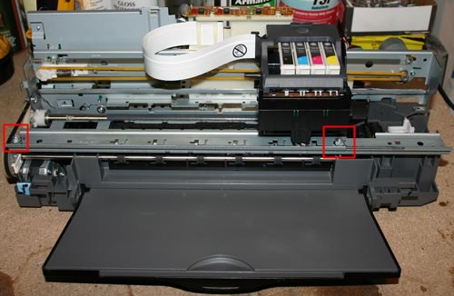
First you need to unscrew the rail, which is screwed with two bolts (see photo above). Unscrewed? We put it aside, we will still need it.

Now notice the 2 bolts near the head cleaning mechanism. We also unscrew them. However, on the left side it is done a little differently, where you can cut off the fasteners.
To remove the entire platform with the head, first, carefully inspect everything and mark with a marker those places where it will be necessary to cut the metal. And then carefully cut the metal with a hand grinder (Dremel, etc.)


Step 4: Cleaning the print head
This step is optional, but since the printer has been completely disassembled, it's best to clean the print head right away. Moreover, there is nothing complicated in this. For this purpose, I used ordinary ear sticks and glass cleaner.

Step 5: Installing the Printhead Platform Part 1
After everything is disassembled and cleaned, it is time to assemble the printer, taking into account the necessary clearance for printing on textolite. Or as the jeepers say "lifting" (i.e. lifting). The amount of lifting depends entirely on the material you are going to print on. In my modification of the printer, I planned to use a steel material feeder with textolite attached to it. The thickness of the material supply platform (steel) was 1.5 mm, the thickness of the foil textolite, from which I usually made boards, was also 1.5 mm. However, I decided that the head shouldn't press too hard on the material, so I chose around 9mm for the gap. Moreover, sometimes I print on double-sided textolite, which is slightly thicker than single-sided.

In order to make it easier for me to control the level of lift, I decided to use washers and nuts, the thickness of which I measured with a caliper. Also, I bought some long bolts and nuts for them. I started with the front feed system.
Step 6 Installing the Printhead Platform Part 2

Before installing the print head platform, small jumpers must be made. I made them from the corners, which I sawed into 2 parts (see photo above). Of course, you can make them yourself.


After, I marked the holes for drilling in the printer. The bottom holes are easy to mark and drill. Then, immediately screwed the brackets into place.

The next step is to mark and drill the upper holes in the platform, this is somewhat more difficult to do, because. everything should be on the same level. To do this, I put a couple of nuts at the docking points of the platform with the base of the printer. Using a level, make sure the platform is level. We mark the holes, drill and tighten with bolts.


Step 7 "Lifting" the print head cleaning mechanism
When the printer finishes printing, the head is "parked" in the head cleaning mechanism where the head nozzles are cleaned to prevent them from drying out and clogging. This mechanism also needs to be raised a little.

I fixed this mechanism with the help of two corners (see photo above).
Step 8: Feed System
At this stage, we will consider the manufacturing process of the supply system and the installation of the material supply sensor.

When designing the feed system, the first problem was the installation of a material feed sensor. Without this sensor, the printer would not function, but where and how to install it? When paper passes through the printer, this sensor tells the printer controller when the top of the paper has passed, and based on that data, the printer calculates the exact position of the paper. The feed sensor is a conventional photo sensor with an emitting diode. When passing paper (in our case material), the beam in the sensor is interrupted.
For the sensor and feed system, I decided to make a platform out of plywood.

As you can see in the photo above, I glued several layers of plywood together in order to make the feed flush with the printer. In the far corner of the platform, I fixed the feed sensor through which the material will pass. In the plywood, I made a small cut to insert the sensor.


The next task was the need to make guides. For this, I used aluminum corners, which I glued to plywood. It is important that all angles are clearly 90 degrees and the guides are strictly parallel to each other. As a feed material, I used an aluminum sheet, on which copper-plated textolite will be laid and fixed for printing.


I made the material feed sheet from an aluminum sheet. I tried to make the sheet size approximately equal to A4 format. After reading a little on the Internet on the operation of the paper feed sensor and the printer as a whole, I found out that for correct operation printer, it is necessary to make a small cutout in the corner of the material feed sheet so that the sensor works a little later than the feed rollers start to spin. The length of the cut was about 90mm.

After everything was done, I fixed a regular sheet of paper on the feed sheet, installed all the drivers on the computer and made a test print on a regular sheet.
Step 9: Refill the ink cartridge

The last part of the printer modification is devoted to ink. Conventional Epson ink is not resistant to chemical processes that occur during etching of the printed circuit board. Therefore, special ink is needed, they are called Mis Pro yellow ink. However, this ink may not be suitable for other printers (non-Epson), because. other types of printheads may be used there (Epson uses a piezoelectric printhead). The online store inksupply.com has delivery to Russia.

In addition to ink, I bought new cartridges, although of course you can use the old ones if you wash them well. Naturally, to refill the cartridges, you will also need an ordinary syringe. Also, I bought a special device for resetting printer cartridges (blue in the photo).
Step 10. Tests

Now let's move on to the print tests. In the design program, I made several blanks for printing, with tracks of various thicknesses.


You can judge the quality of the print from the photos above. Below is a video of the print:
Step 11 Etching
For etching boards made by this method, only a solution of ferric chloride is suitable. Other etching methods (copper sulfate, hydrochloric acid, etc.) may corrode Mis Pro yellow ink. When etching with ferric chloride, it is better to heat the printed circuit board with a heat gun, this speeds up the etching process, and so on. less ink layer "sits down".

The heating temperature, proportions and duration of etching are selected empirically.
From time to time I need to make printed circuit boards for my crafts. LUT is an extremely capricious method for me - either the toner will melt and spread, then the quality of the paper will not work, then some other hemorrhoids - steel-iron nerves are needed. For photoresist, specific reagents and a laminator.
“And if we build a special machine for this? To immediately print with paint? ”, - I thought. “Remake the printer!”, laziness remarked reasonably. A search on the Internet revealed that people successfully remake inkjet printers for printing on textolite, but this is a rather laborious process (you need to finish and raise the frame with the print head, etc.), moreover, I value my inkjet printer like Madame Gritsatsueva sifter (MFP, after all). But I had an unnecessary laser HP lj 6L lying around idle - in general, I was lying around. It was useful to look at the characteristics and accidentally stumbled upon (the cache of the article, for every fireman) on the alteration of this particular printer for textolite. But the topic in the article was not fully revealed - in particular, it does not tell how to make the toner stick to the textolite foil, how to bake this toner later and, most importantly, there is no video demonstration of a working sample, so I brought this matter to mind on your own. I strongly I recommend that you familiarize yourself with the above article, because I will not repeat what is described there in all details - there is nothing to copy-paste. There are many photos under the cut.
So, the alteration itself lies in the little things - make a cut in the back wall, remove the baffle plate and the stove (so that the printed pattern is not smeared). The stove temperature sensor must be replaced with a resistor with a resistance of 8.2 kOhm. I recommend doing it like this (simply short-circuit the temperature sensor with a resistor so as not to fiddle with fixing it):

Nothing needs to be done with the connector that supplies the heating voltage. Unplug the stove and that's it.
Next, you need to work with the impact pad - this is what was behind the paper pickup roller - you need to cut it off, leaving only the sides. I'm sorry, but the photos are from the unsawn back no - I forgot to take a picture, and when I came to my senses and came to my senses, everything was already sawed off. I don't know how it happened. Nightmare.
This is how it should look like:

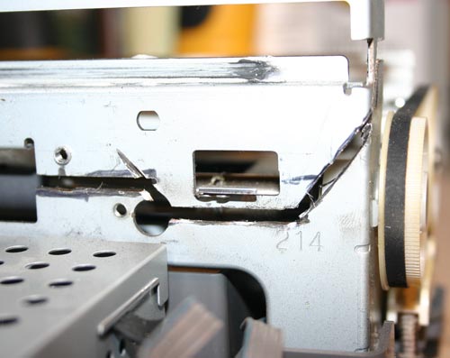
Yes, I almost forgot: be careful with the paper passage sensor (it is, rather, the upper arm of its damper, is located over there to the left of the paper pickup roller) - do not accidentally cut off its fasteners, otherwise the printer will not be able to control the end of the sheet in the feed path.

But at the paper presence sensor, on the contrary, remove the shutter, and it will seem to the printer that there is always “paper” there.

Back view:

That's all I wanted to clarify about the rework. And now no less important points- sticking the toner to the foil and fixing it with heat. 
And, of course, what we are all here for is a video demonstration of the device:
That's all. This machine has made my life much easier. I have successfully printed more than one board with it, pah-pah. If this is useful to someone, I will be very happy. Thank you for your attention.
Almost everyone involved in radio engineering is faced with the fact that with an increase in the number of boards created, it takes a lot of time and effort to draw the tracks correctly. Not to mention their etching, tinning and soldering ...
But what if part of the processes can be automated? Of course, this is not about conveyor production or about putting the printing of circuits on a professional stream.
Yes, for yourself. Moreover, along with a reduction in the time of transferring the scheme to the textolite, they come:
1.High accuracy (even with simple inkjet printers, you can achieve sufficient quality to transfer closely spaced tracks that are very difficult to draw by hand);
2. Elimination of errors (if the printed circuit board has already been drawn in detail in the program, its printed version will fully correspond to the intended layout, you will not accidentally draw the wrong track, do not shift the contact seat, etc.).
Solutions
1.Of course, if you manufacture a large number of printed circuit boards, then it's time to think about buying professional equipment (for example, UV printers).
2. The printing device can be made by hand from scratch (assembled from guides, stepper motors, etc.).
3.Remake an old and unnecessary printer.
Of all the above, the alteration sounds the most real.
As a donor, it is best to consider (in descending order of priority):
1.Inkjet printers (black and white or color);
2.Laser printers.
Here it is immediately worth mentioning that many modern models are equipped with various methods of protection against external interference. Manufacturers block printing from non-original cartridges, check ink consumption for each cartridge, etc.
Therefore, for rework, it is best to take old printing devices with a simple design and without any protection.
Example based on Epson C84 inkjet printer
As an analogue, you can try to adapt the process for all devices from the C80 series.
The printer itself looks like this before the alteration:
Rice. 1. Appearance of the printer
Instruction step by step:
1. We take out the trays;
2. Remove the casing (outer casing). It should turn out like this.

Rice. 2. Start disassembling the printer
3. Turn off and unscrew the paper feed sensor.
His appearance.

Rice. 3. Paper feed sensor
4. Remove the pinch rollers.

Rice. 4. Pinch rollers
5. We dismantle the system for cleaning the print heads.

Rice. 5. Print head cleaning system
6. Unscrew and raise the platform with print heads. Let's start with this rail.

Rice. 6. Removing the printhead platform
7. Using an angle grinder with a cutting disc for metal of small diameter, carefully cut off the platform. See photo.


Rice. 7. Slice platform
8.Now the free print bed can be raised to the required height (depending on what material you are going to print on). This will require jumpers (any metal plates with conveniently located holes will do).

Rice. 8. Jumpers on the printer body
9.Drill holes in the printing platform and attach to the base. This is the most important stage, for the sake of which everything was started. "Lifting" (rise) must be accurately calculated in advance. If you don’t get the dimensions right or place the printing platform crooked, it will be difficult to redo it (measure and re-drill everything in a new way, or select new jumpers). It is best to use a lining of a given thickness at the stage of setting the gap.
We twist.

Rice. 9. M Printer installation platforms
10.To prevent the ink from drying on the print head after using the printer, the nozzle cleaning mechanism must be replaced. However, due to the fact that the platform has been raised, the cleaning mechanism will also have to be raised. For example, yes.

Rice. 10. Mounting the nozzle cleaning mechanism
11. We make a platform for sheet feeding (replacement of the lower tray). The platform can be made from plywood, hardboard, etc. sheet materials that are at hand.

Rice. 11. Sheet feeding platform
12. We attach the guides to the platform (they must be strictly parallel to each other) and the sheet feed sensor.

13. We replace the paper with a durable sheet material (for example, aluminum sheet, A4 format is implied), however, in order for the paper feed sensor to work correctly (it also changed its location after dismantling), a cutout (90 mm) should be made in the sheet.

Rice. 13. Sheet material
14. Install the drivers, connect the printer to the PC (as usual).
15. Refill the cartridge with Mis Pro yellow ink (only they are resistant to the chemical reaction of etching with ferric chloride and are suitable for Epson nozzles with a piezoelectric head).
16. We print our scheme. We fasten the textolite to an aluminum sheet.
17. We etch the board (only in a solution of ferric chloride, to speed up the process, you can heat it with a hairdryer).

Rice. 14. View of the assembled printer
Publication date: 24.01.2018
Readers' opinions
- Eduard / 18.02.2019 - 11:58
Class! Respect to you and respect))) for a quality guide!)))
Lately I've been looking for ways to make PCB fabrication easier. About a year ago, I came across an interesting article that described the process of modifying an Epson inkjet printer to print on thick materials, incl. on copper textolite. The article described the completion of the Epson C84 printer, however, I had an Epson C86 printer, but because Since the mechanics of Epson printers, I think everyone is similar, I decided to try to upgrade my printer. In this article, I will try to describe in as much detail as possible, step by step, the process of upgrading the printer for printing on copper-plated textolite.
Necessary materials:
- Well, of course, you will need the Epson C80 family printer itself.
- a sheet of aluminum or steel material
- clamps, bolts, nuts, washers
- a small piece of plywood
- epoxy or superglue
- ink (more on that later)
Instruments:
- grinder (Dremel, etc.) with a cutting wheel (you can try a small monkey)
- various screwdrivers, wrenches, hexagons
- drill
— hot air gun
Step 1. Disassemble the printer
The first thing I did was remove the rear paper output tray. After that, you need to remove the front tray, side panels and then the main body.
The photos below show the detailed process of disassembling the printer:


Step 2. Remove the internal elements of the printer
After the printer case is removed, it is necessary to remove some of the internal elements of the printer. First, you need to remove the paper feed sensor. In the future, we will need it, so do not damage it when removing it.
Then, it is necessary to remove the central pressure rollers, because. they can interfere with PCB feeding. In principle, the side rollers can also be removed.

And finally, you need to remove the printhead cleaning mechanism. The mechanism is held on by latches and is removed very simply, but when removing, be very careful, because. It has different tubes.

Disassembly of the printer is complete. Now let's start his "lifting".
Step 3: Remove the printhead platform
We begin the process of upgrading the printer. Work requires accuracy and the use of protective equipment (eyes must be protected!).
First you need to unscrew the rail, which is screwed with two bolts (see photo above). Unscrewed? We put it aside, we will still need it.

Now notice the 2 bolts near the head cleaning mechanism. We also unscrew them. However, on the left side it is done a little differently, where you can cut off the fasteners.
To remove the entire platform with the head, first, carefully inspect everything and mark with a marker those places where it will be necessary to cut the metal. And then carefully cut the metal with a hand grinder (Dremel, etc.)


Step 4: Cleaning the print head
This step is optional, but since the printer has been completely disassembled, it's best to clean the print head right away. Moreover, there is nothing complicated in this. For this purpose, I used ordinary ear sticks and glass cleaner.

Step 5: Installing the Printhead Platform Part 1
After everything is disassembled and cleaned, it is time to assemble the printer, taking into account the necessary clearance for printing on textolite. Or, as the jeepers say, “lifting” (i.e. lifting). The amount of lifting depends entirely on the material you are going to print on. In my modification of the printer, I planned to use a steel material feeder with textolite attached to it. The thickness of the material supply platform (steel) was 1.5 mm, the thickness of the foil textolite, from which I usually made boards, was also 1.5 mm. However, I decided that the head shouldn't press too hard on the material, so I chose around 9mm for the gap. Moreover, sometimes I print on double-sided textolite, which is slightly thicker than single-sided.

In order to make it easier for me to control the level of lift, I decided to use washers and nuts, the thickness of which I measured with a caliper. Also, I bought some long bolts and nuts for them. I started with the front feed system.
Step 6 Installing the Printhead Platform Part 2
Before installing the print head platform, small jumpers must be made. I made them from the corners, which I sawed into 2 parts (see photo above). Of course, you can make them yourself.


After, I marked the holes for drilling in the printer. The bottom holes are easy to mark and drill. Then, immediately screwed the brackets into place.

The next step is to mark and drill the upper holes in the platform, this is somewhat more difficult to do, because. everything should be on the same level. To do this, I put a couple of nuts at the docking points of the platform with the base of the printer. Using a level, make sure the platform is level. We mark the holes, drill and tighten with bolts.

Step 7 Lifting the Print Head Cleaning Mechanism
When the printer finishes printing, the head is “parked” in the head cleaning mechanism where the head nozzles are cleaned to prevent them from drying out and clogging. This mechanism also needs to be raised a little.

I fixed this mechanism with the help of two corners (see photo above).
Step 8: Feed System
At this stage, we will consider the manufacturing process of the supply system and the installation of the material supply sensor.

When designing the feed system, the first problem was the installation of a material feed sensor. Without this sensor, the printer would not function, but where and how to install it? As the paper passes through the printer, this sensor tells the printer controller when the top of the paper passes, and based on this data, the printer calculates the exact position of the paper. The feed sensor is a conventional photo sensor with an emitting diode. When passing paper (in our case material), the beam in the sensor is interrupted.
For the sensor and feed system, I decided to make a platform out of plywood.
As you can see in the photo above, I glued several layers of plywood together in order to make the feed flush with the printer. In the far corner of the platform, I fixed the feed sensor through which the material will pass. In the plywood, I made a small cut to insert the sensor.


The next task was the need to make guides. For this, I used aluminum corners, which I glued to plywood. It is important that all angles are clearly 90 degrees and the guides are strictly parallel to each other. As a feed material, I used an aluminum sheet, on which copper-plated textolite will be laid and fixed for printing.


I made the material feed sheet from an aluminum sheet. I tried to make the sheet size approximately equal to A4 format. After reading a little on the Internet about the operation of the paper feed sensor and the printer as a whole, I found out that for the printer to work correctly, it is necessary to make a small cutout in the corner of the material feed sheet so that the sensor works a little later than the feed rollers start spinning. The length of the cut was about 90mm.

After everything was done, I fixed a regular sheet of paper on the feed sheet, installed all the drivers on the computer and made a test print on a regular sheet.
Step 9: Refill the ink cartridge

The last part of the printer modification is devoted to ink. Conventional Epson ink is not resistant to chemical processes that occur during etching of the printed circuit board. Therefore, special ink is needed, they are called Mis Pro yellow ink. However, this ink may not be suitable for other printers (non-Epson), because. other types of printheads may be used there (Epson uses a piezoelectric printhead). The online store inksupply.com has delivery to Russia.
In addition to ink, I bought new cartridges, although of course you can use the old ones if you wash them well. Naturally, to refill the cartridges, you will also need an ordinary syringe. Also, I bought a special device for resetting printer cartridges (blue in the photo).
Step 10. Tests

Now let's move on to the print tests. In the Eagle design program, I made several printables, with tracks of various thicknesses.


You can judge the quality of the print from the photos above. Below is a video of the print:
Step 11 Etching
For etching boards made by this method, only a solution of ferric chloride is suitable. Other etching methods (copper sulfate, hydrochloric acid, etc.) may corrode Mis Pro yellow ink. When etching with ferric chloride, it is better to heat the printed circuit board with a heat gun, this speeds up the etching process, and so on. less ink layer "eats away".
The heating temperature, proportions and duration of etching are selected empirically.


A. VOVK, Angarsk, Irkutsk region
The proposed method for forming a mask that protects future conductors on a printed circuit board blank during its etching can be widely used by radio amateurs and specialists involved in the design and manufacture of prototypes of devices and equipment, repair of failed components. It is cheap, convenient, easily reproducible, does not require the use of harmful, aggressive or scarce reagents, expensive equipment and tooling.
In the overwhelming majority of cases, printed circuit boards are manufactured by etching unprotected areas of the foil on the board blank. To form a protective mask, photoresist, paints and varnishes, special inks, printer toner, and other substances and mixtures that are resistant to etching solution are used.
The determining factor in the process of preparing the board blank for etching is the choice of the method of applying a protective mask to it. Recently, laser-ironing and photoresistive methods have become popular, but in order to obtain an acceptable quality mask, they require a rather lengthy development of the process.
The way I propose to apply a protective mask differs in that the printer prints it directly onto a specially prepared surface of the board blank foil. This does not require auxiliary and intermediate mask image carriers and operations associated with them. For printing, an inkjet printer with conventional water-soluble inks based on dye or pigment was used.
Since copper foil is poorly wetted with ink, it is necessary to apply a thin layer of edible gelatin solution on its surface, which prevents the ink from spreading on the foil, knocking them into drops and ensures uniform distribution over the surface without gaps, which can later lead to marriage.
The idea of printing onto a board blank in a CD tray on a printer that has this feature has been around for a long time. Since you often deal with small boards, you can place from two to six of them in a tray, even if you leave the central hole for fixing the disk intact. It was only necessary to find a suitable inexpensive printer and make sure that its program allows you to transfer the pattern of PCB conductors without distortion .
The choice fell on three inkjet printers that have the same cost and technical capabilities, - CANON PIXMA iP 4500, EPSON Stylus Photo R270 and HP Photosmart D5463. The print-to-disk programs for the last two of them turned out to be too primitive - an inconvenient interface and a minimum of functions.
The most serious was the CD-Label Print program from the kit
CANON PIXMA iP 4500 - normal control panel, scalable. A ruler is provided, which is very important when working with boards. From the Autodesk Actrix 2000 program, the drawing (via the function in the Paste Special menu) could be transferred without transformation, but from the Sprint Layout 5.0 program this could not be done.
Only the central hole for fixing the disk in the tray was embarrassing, it took up too much space and did not allow processing larger printed circuit boards.
It was decided to try to print not in the CD-Label Print program, but to use the main print driver, and everything worked out fine. Now maximum dimensions boards without alteration of the drawer increased to 85x85 mm, with alteration - 120x120 mm. Why choose Autodesk Actrix 2000? Firstly, it is very versatile, allows you to draw circuit diagrams, drawings, printed circuit boards. Secondly, it has a large information base electrical and electronic components. But most importantly, they are easy to create, the elements look natural, freely transferred to the working field. There are automatic snapping to the grid, line ends, hole centers, convenient scaling when drawing and printing, selection of line thickness, color, font, background, etc.
First, in the Autodesk Actrix 2000 program, a drawing of the future printed circuit board is designed (consider a one-sided version). Save it in your working directory in case you accidentally change or delete it.
Next, in the menu (File-Page Setup...), the page dimensions are set (131x242.5 mm), they completely repeat the dimensions of the drawer for printing on CDs - they create a mask template (Fig. 1). The circle is drawn in the place where it is actually placed (check with a ruler). Save the template as an object with a name so that it can be opened.
If the board is small, the workpiece (its thickness is not more than 1 mm) is glued with a piece of double-sided adhesive tape to a free space. It should not protrude above the surface of the bottom of the tray. Then the outline of the board is printed (directly onto the plastic). The next workpiece is installed in this place. It is better to choose its dimensions with a small allowance, and then bring it to the desired size with a file or sandpaper.
If the board is large, you will have to cut off the ledge for mounting the disk in the center of the tray.
With board dimensions of 120x120 mm, you will have to modify the tray - remove (cut off) the plastic to a depth of 1.5 mm in
| No. p / p | Operation | Equipment, materials, mode |
| 1 | Application of a special coating on a foil dielectric and drying of the coating | 60...80% edible gelatin solution By hand with a brush (nylon) or a rotating roller (nylon). 5 min at room temperature or hot air gun 0.5...1 min at 60...70 °C |
| 2 | Printing a protective mask, soaking a special coating under a layer of ink | Inkjet Printer for CD Printing |
| 3 | Application of the polymer and its diffusion into the liquid structure of the ink and a special coating | Styrene acrylic polymer (toner). Manual brush (squirrel hair) or rotating |
| 4 | Removal of excess polymer | By hand with a brush (squirrel hair) or a rotating roller (squirrel hair) |
| 5 | Evaporation of the liquid components of the ink, baking the paste | 0.5...1 min at 180...200°C |
| 6 | Washing the board with water, removing excess polymer and special coating | Water Manual brush (squirrel hair) or rotary roller (squirrel hair) |
| 7 | Etching the board on the formed protective mask | Ferric chloride solution, 60...70°C |
| 8 | Removing the protective mask | Thinner 646. 647, cotton swab or soft cloth |
four corners shown in Fig. 1 in blue. The easiest way to do this is to milling machine, but it is also possible by hand, since the plastic is quite soft. You can use a simple cutter, the same as for cutting organic glass, but with a wider - 3 ... 4 mm - cutting edge, or an electric drill with a set of coarse-grained abrasive nozzles. The inner shiny square in the recess is designed to recognize the presence of a disk, therefore, when printing a board, it must be closed with it, otherwise the printer will pull out the tray.
Double-sided boards are made in two passes. First, one layer is printed and baked (see below for more on this), then another one is also baked. For a more accurate alignment of the sides, clamps should be provided.
In the table and in fig. Figure 2 shows the main operations for forming a protective mask by the inkjet-diffusion method for single-sided printed circuit boards. It is easy to see that the inkjet-diffusion method of forming a protective mask does not require pre-pressing and heating; allows the use of foil materials with a pronounced dielectric structure (large fiberglass mesh, significant fiber thickness, etc.) and small defects, micro-scratches on the foil; does not introduce raster, diffraction, geometric distortions (unlike the use of a photomask). In the manufacture of double-sided printed circuit boards, the positioning of the layers can be easily ensured by the established reference points directly in computer program, in which the wiring of conductors is made, without mechanical alignment and the use of microscopes and special equipment. The time spent on preparing the board for etching is minimal.
Mask ink, unlike printing on paper, is held on the surface of the workpiece due to a special coating. Image remains raw pretty long time(several hours), so you can’t touch the surface with your hands, you need to take the workpiece only by the side edges. A finely dispersed styrene-acrylic polymer (toner) is used as a fixative. It has the ability to intensively diffuse into the ink while enveloping its particles. In other words, the ink acts as a dispersant, and the polymer acts as a dispersed phase. The ink does not spread due to surface tension and high viscosity at the points of contact with the coating.
It soaks under a layer of ink, and the polymer also diffuses into it.
Toner is applied with tangential movements (squirrel brush) in all directions to a raw, freshly printed mask. Before that, it is advisable, without touching it, to lightly powder with toner and gently shake off the excess.
As a result, a pasty colloidal solution (suspension) is formed on the workpiece, resistant to destruction to the necessary extent, completely repeating the printed pattern. The ink does not have any significant effect on the gaps, since the polymer immediately fixes the edge of all future conductors and prevents them from spreading, giving the image a clearly defined look.
Excess polymer is carefully removed, for example, with a squirrel brush or a rotating roller (optionally, vacuum suction can be used). Small areas can be scraped off with a wooden toothpick under a magnifying glass. Poorly cleaned residues can be baked and not washed off with water.
Then, with a hot air gun (or over the flame of a gas burner, being careful) baking is performed at a temperature of about 180 ... 200 ° C, the liquid components that make up the ink evaporate. Due to the low concentration of the polymer in the gaps, its baking does not occur. It is necessary to bake I until the characteristic smell of melted plastic appears. The coating should be dense and acquire a slight sheen, otherwise everything will be washed off during the washing stage.

Washing with water should remove any excess polymer that has not entered the ink. At the same time, the gelatin coating is washed off from the gaps. Protective mask presents
I is a caked mass that is resistant to an etching solution and has high adhesion to the surface of the workpiece. To increase the thickness of the mask layer, it is allowed to reapply ink to the already formed and baked pattern (gelatin is no longer applied). This can be useful with a large area of the workpiece to increase the resistance of the mask, but will require very precise re-installation of the workpiece in the tray.
The process of forming a protective mask is implemented on a commercially available inkjet printer general purpose CANON PIXMA iP 4500.
Software: operating system - Windows Vista Home Premium, PCB wiring - Autodesk Actrix 2000, print driver - CANON PIXMA iP 4500.
Print Mode: Color Intensity - Manual, Intensity - +50, Contrast - +50, Brightness - Normal, Print Quality - High, Media Type - CD Recommended, Paper Source - I Disc Tray, Page Size - CD-R-F Tray (131.0x242.5 mm).
The minimum width of conductors and gaps is 200 µm.
Printing is done on the place where the drawing of the future board is transferred. Any color should be chosen, except for black, since it is difficult to control the degree of application of the black polymer on a black background. Double-sided printed circuit boards must be firmly fixed in the printer tray so that they fall accurately when turned over into the same place. Combination of images of conductors on the first and second layers is carried out in the Autodesk Actrix 2000 program itself according to the reference points set on the coordinate grid. The alignment accuracy determines the selected grid cell size value.
It takes no more than 10 ... 15 minutes to manufacture a high-quality printed circuit board with dimensions of 85x85 mm (plus the time for preparing the drawing of future conductors and the etching time).
For the method of manufacturing boards described above, a styrene-acrylic polymer (toner) with a particle size of 3 ... 4 μm is suitable, which is used in laser printers and photocopiers of most foreign companies - XEROX, HP, CANON, SAMSUNG, etc. It should be noted that toners different manufacturers have slightly different melting points.
A special coating is an aqueous solution of edible gelatin, and already swollen gelatin is not diluted, but it is taken that is not brought to full swelling, that is, the most active components that make up the gelatin that have passed into the solution are used.
It is better to use edible gelatin sold in the form of crystals or granules. One part of gelatin will require five parts of boiled cold water (by volume).
Gelatin swells 5 ... 10 minutes (depending on its quality). The solution is stirred periodically. It should acquire such a viscosity that when applied to the workpiece it does not leave gaps, but at the same time it does not reach for the brush, and after application it spreads a little more. The gelatin crystals that have not passed into the solution are removed from the brush on the edge of the dish and removed.
Left for a long time, the solution turns into jelly (gelatin swells completely) and becomes unusable.
The coating should be uniform (not have stripes), and after drying, acquire a slightly iridescent hue. It dries quickly, but you can speed it up with a hair dryer. If any defects are found when viewing under a magnifying glass, it is better to wash off the coating and apply a new one. You can wash off already printed drawing.
When etching, do not overexpose the boards in the solution and use too intensive mixing methods to prevent peeling of the protective mask.
Note that Sprint Layout 5.0 does not tie the created project to the selected page size, so a test print will be required.
You may be interested in: