Over the past few years, I have been regularly faced with the tasks of developing UWB (ultra-wideband) microwave modules and functional units. And no matter how sad it is for me to talk about it, I draw almost all the information on the topic from foreign sources. However, some time ago, in search of the information I needed, I stumbled upon one that promised a solution to all my problems. I want to talk about how the solution of problems did not work out.
One of the constant "headaches" in the development of UWB microwave devices is the development of UWB antennas, which must have a set of specific properties. Among these properties are the following:
1. Coordination in the operating frequency band (for example, from 1 to 4 GHz). However, it happens when it is necessary to agree in the frequency range from 0.5 GHz to 5 GHz. And here the problem arises to go down in frequency below 1 GHz. In general, I got the impression that the frequency of 1 GHz has some kind of mystical power - you can get close to it, but it is very difficult to overcome it, because. in this case, another requirement for the antenna is violated, namely
2. Compactness. After all, it's no secret to anyone that now few people need a waveguide horn antenna of enormous dimensions. Everyone wants the antenna to be small, light and compact so that it can be tucked into a case. portable device. But with the compactification of the antenna, it becomes very difficult to comply with paragraph 1 of the requirements for the antenna, since the minimum frequency of the operating range is closely related to the maximum size of the antenna. Someone will say that you can make an antenna on a dielectric with a high relative permittivity ... And he will be right, but this contradicts the next item on our list, which says that
3. The antenna should be as cheap as possible and made on the basis of the most accessible and inexpensive materials (for example, FR-4). Because no one wants to pay a lot, a lot of money for an antenna, even if it is three times brilliant. Everyone wants the cost of the antenna at the PCB manufacturing stage to go to zero. Because this is our world...
4. There is one more requirement that arises when solving various problems associated, for example, with short-range location, as well as with the creation various sensors using UWB technology (here it should be clarified that we are talking about applications with low power, where every dBm counts). And this requirement states that the radiation pattern (DN) of the designed antenna should be formed in only one hemisphere. What is it for? In order for the antenna to “shine” in only one direction, without dissipating precious power into the “return”. It also improves a number of indicators of the system in which such an antenna is used.
Why am I writing all this..? In order for the inquisitive reader to understand that the developer of such an antenna is faced with a lot of restrictions and prohibitions that he needs to overcome heroically or witty.
And suddenly, as a revelation, an article appears that promises a solution to all the above problems (as well as those that were not mentioned). Reading this article causes a slight feeling of euphoria. Although the first time you don’t fully comprehend what is written, the magic word “fractal” sounds very promising, because. Euclidean geometry has already exhausted its arguments.

We take up the matter boldly and feed the structure proposed by the author of the article to the simulator. The simulator groans inwardly with a computer cooler, chewing gigabytes of numbers, and spits out the digested result... Looking at the simulation results, you feel like a little deceived boy. Tears well up in my eyes, because. again your childhood aerial dreams came across a cast-iron ... reality. There is no agreement in the frequency range 0.1 GHz - 24 GHz. Even in the range of 0.5 GHz - 5 GHz there is nothing similar.

There is still a timid hope that you did not understand something, did something wrong ... The search for the inclusion point begins, various variations with the topology, but all in vain - it is dead!
The saddest thing in this situation is that until the last moment you are looking for the cause of failure in yourself. Thanks to the comrades in the shop, who explained that everything is correct - it should not work.
P.S. I hope my Friday post made you smile.
The moral of the story is this - be careful!
(And I also really wanted to write an ANTI-article about this, because they deceived me).
Wire fractal antennas, investigated in this thesis, were made by bending the wire according to a paper template printed on a printer. Since the wire was bent manually using tweezers, the accuracy of manufacturing the "bends" of the antenna was about 0.5 mm. Therefore, the simplest geometric fractal forms were taken for research: the Koch curve and the "bipolar jump" of Minkowski.
It is known that fractals make it possible to reduce the size of antennas, while the dimensions of the fractal antenna are compared with the dimensions of a symmetrical half-wave linear dipole. In further studies in the thesis, wire fractal antennas will be compared with a linear dipole with /4-arms equal to 78 mm with a resonant frequency of 900 MHz.
Wire fractal antennas based on the Koch curve
The paper provides formulas for calculating fractal antennas based on the Koch curve (Figure 24).
a) n= 0 b) n= 1 c) n = 2
Figure 24 - Koch curve of various iterations n
Dimension D generalized Koch fractal is calculated by the formula:
If in formula (35) we substitute the standard bending angle of the Koch curve = 60, then we get D = 1,262.
Dependence of the first resonant frequency of the Koch dipole f K on the dimension of the fractal D, iteration numbers n and resonant frequency of a rectilinear dipole f D of the same height as the Koch broken line (at the extreme points) is determined by the formula:

For Figure 24, b with n= 1 and D= 1.262 from formula (36) we obtain:
f K= f D 0.816, f K = 900 MHz 0.816 = 734 MHz. (37)
For Figure 24, c with n = 2 and D = 1.262, from formula (36) we obtain:
f K= f D 0.696, f K = 900 MHz 0.696 = 626 MHz. (38)
Formulas (37) and (38) also allow us to solve the inverse problem - if we want fractal antennas to operate at a frequency f K = 900 MHz, then the straight dipoles must operate at the following frequencies:
for n = 1 f D = f K / 0.816 = 900 MHz / 0.816 = 1102 MHz, (39)
for n = 2 f D = f K / 0.696 = 900 MHz / 0.696 = 1293 MHz. (40)
According to the graph in Figure 22, we determine the lengths of the /4-arms of a rectilinear dipole. They will be equal to 63.5 mm (for 1102 MHz) and 55 mm (for 1293 MHz).
Thus, 4 fractal antennas were fabricated based on the Koch curve: two with dimensions /4-arms of 78 mm, and two with smaller dimensions. Figures 25-28 show images of the PK2-47 screen, which can be used to experimentally determine the resonant frequencies.
Table 2 summarizes the calculated and experimental data, from which it can be seen that the theoretical frequencies f T differ from the experimental f E no more than 4-9%, and this is quite a good result.

Figure 25 - PK2-47 screen when measuring the antenna with the Koch curve of iteration n = 1 with /4-shoulders equal to 78 mm. Resonance frequency 767 MHz

Figure 26 - Screen PK2-47 when measuring the antenna with the Koch curve of iteration n = 1 with /4-shoulders equal to 63.5 mm. Resonance frequency 945 MHz

Figure 27 - Screen PK2-47 when measuring the antenna with the Koch curve of iteration n = 2 with /4-shoulders equal to 78 mm. Resonant frequency 658 MHz

Figure 28 - Screen PK2-47 when measuring the antenna with the Koch curve of iteration n = 2 with /4-shoulders equal to 55 mm. Resonance frequency 980 MHz
Table 2 - Comparison of calculated (theoretical fT) and experimental fE resonant frequencies of fractal antennas based on the Koch curve
Wire fractal antennas based on "bipolar jump". radiation pattern
Fractal lines of the "bipolar jump" type are described in the work, however, formulas for calculating the resonant frequency depending on the size of the antenna are not given in the work. Therefore, it was decided to determine the resonant frequencies experimentally. For simple fractal lines of the 1st iteration (Figure 29, b), 4 antennas were made - with a length of /4-arm equal to 78 mm, with half the length and two intermediate lengths. For difficult-to-manufacture fractal lines of the 2nd iteration (Figure 29, c), 2 antennas were made with lengths /4-arms of 78 and 39 mm.
Figure 30 shows all the fabricated fractal antennas. Figure 31 shows the appearance of the experimental setup with the "bipolar jump" fractal antenna of the 2nd iteration. Figures 32-37 show the experimental determination of resonant frequencies.
a) n= 0 b) n= 1 c) n = 2
Figure 29 - Minkowski curve "bipolar jump" of various iterations n

Figure 30 - Appearance all manufactured wire fractal antennas (wire diameters 1 and 0.7 mm)

Figure 31 - Experimental setup: panoramic VSWR and attenuation meter RK2-47 with a fractal antenna of the "bipolar jump" type of the 2nd iteration


Figure 32 - Screen PK2-47 when measuring the antenna "bipolar jump" iteration n = 1 with /4-arms equal to 78 mm.
Resonance frequency 553 MHz

Figure 33 - Screen PK2-47 when measuring the antenna "bipolar jump" iteration n = 1 with /4-arms equal to 58.5 mm.
Resonant frequency 722 MHz

Figure 34 - Screen PK2-47 when measuring the antenna "bipolar jump" iteration n = 1 with /4-arms equal to 48 mm. Resonance frequency 1012 MHz

Figure 35 - Screen PK2-47 when measuring the antenna "bipolar jump" iteration n = 1 with /4-arms equal to 39 mm. Resonant frequency 1200 MHz


Figure 36 - Screen PK2-47 when measuring the antenna "bipolar jump" iteration n = 2 with /4-arms equal to 78 mm.
The first resonant frequency is 445 MHz, the second is 1143 MHz

Figure 37 - PK2-47 screen when measuring the "bipolar jump" antenna of iteration n = 2 with /4-arms equal to 39 mm.
Resonance frequency 954 MHz
As the experimental studies have shown, if we take a symmetrical half-wave linear dipole and a fractal antenna of the same length (Figure 38), then fractal antennas of the “bipolar jump” type will operate at a lower frequency (by 50 and 61%), and fractal antennas in the form of a curve Koch work at frequencies lower by 73 and 85% than that of a linear dipole. Therefore, indeed, fractal antennas can be made smaller. Figure 39 shows the dimensions of fractal antennas for the same resonant frequencies (900-1000 MHz) in comparison with the arm of a conventional half-wave dipole.

Figure 38 - "Regular" and fractal antennas of the same length

Figure 39 - Antenna dimensions for the same resonant frequencies
5. Measuring the radiation patterns of fractal antennas
Antenna patterns are usually measured in "anechoic" chambers, the walls of which absorb the radiation incident on them. In this thesis, the measurements were carried out in a regular laboratory of the Faculty of Physics and Technology, and the reflected signal from metal cases instruments and iron stands introduced some error in the measurements.
As a microwave signal source, we used our own generator of a panoramic VSWR and attenuation meter RK2-47. An ATT-2592 electromagnetic field level meter was used as a radiation receiver of the fractal antenna, which allows measurements in the frequency range from 50 MHz to 3.5 GHz.
Preliminary measurements showed that the radiation pattern of a symmetrical half-wave linear dipole significantly distorts the radiation from the outside of the coaxial cable, which was directly (without matching devices) connected to the dipole. One way to suppress the transmission line radiation is to use a monopole instead of a dipole, together with four mutually perpendicular /4 "counterweights" that play the role of "ground" (Figure 40).


Figure 40 - /4 monopole and fractal antenna with "counterweights"
Figures 41 - 45 show the experimentally measured radiation patterns of the studied antennas with "counterweights" (the resonant frequency of the radiation practically does not change when going from a dipole to a monopole). Measurements of the power flux density of microwave radiation in microwatts per square meter were carried out in the horizontal and vertical planes through 10. The measurements were carried out in the "far" zone of the antenna at a distance of 2.
An antenna in the form of a rectilinear /4-vibrator was studied first. It can be seen from the radiation pattern of this antenna (Figure 41) that it differs from the theoretical one. This is due to measurement errors.
The measurement errors for all antennas under study can be as follows:
Reflection of radiation from metal objects inside the laboratory;
The absence of strict mutual perpendicularity between the antenna and counterweights;
Not completely suppressing the radiation of the outer sheath of the coaxial cable;
Inaccurate reading of angular values;
Inaccurate "targeting" of the ATT-2592 meter to the antenna;
Interference from cell phones.
The first thing I would like to write about is a small introduction to the history, theory and use of fractal antennas. Fractal antennas have been recently discovered. They were first invented by Nathan Cohen in 1988, then he published his research on how to make a TV antenna out of wire and patented it in 1995.
The fractal antenna has several unique characteristics, as written on Wikipedia:
"A fractal antenna is an antenna that uses a fractal, self-repeating design to maximize the length or increase the perimeter (at internal sites or external structure) of a material that can receive or transmit electromagnetic signals within a given total surface area or volume."
What exactly does this mean? Well, you need to know what a fractal is. Also from Wikipedia:
“A fractal is typically a rough or fragmented geometric shape that can be split into parts, each of which will be a reduced-size copy of the whole — a property called self-similarity.”
Thus, a fractal is a geometric shape that repeats itself over and over again, regardless of the size of the individual parts.
Fractal antennas have been found to be about 20% more efficient than conventional antennas. This can be useful especially if you want your TV antenna to receive digital or high definition video, increase cellular range, Wi-Fi range, FM or AM radio reception, etc.
Most cell phones already have fractal antennas. You may have noticed this because mobile phones no longer have antennas outside. This is because they have fractal antennas etched into the circuit board inside them, which allows them to receive a better signal and pick up more frequencies, such as Bluetooth, cellular and Wi-Fi from one antenna.
Wikipedia:
“The response of a fractal antenna is markedly different from traditional antenna designs in that it is capable of operating with good performance at different frequencies simultaneously. The frequency of standard antennas must be cut to be able to receive only that frequency. Therefore, a fractal antenna, unlike a conventional one, is an excellent design for broadband and multi-band applications.”
The trick is to design your fractal antenna to resonate at the specific center frequency you want. This means that the antenna will look different depending on what you want to receive. To do this, you need to apply mathematics (or an online calculator).
In my example I am going to do a simple antenna, but you can make it more complex. The more difficult the better. I'll be using a spool of 18 strand solid core wire to make the antenna, but you can customize your own circuit boards to suit your aesthetics, make it smaller or more complex with more resolution and resonance.
I am going to make a TV antenna to receive digital TV or TV high definition. These frequencies are easier to work with and range in length from about 15 cm to 150 cm for half a wavelength. For simplicity and cheapness of parts, I'm going to place it on a common dipole antenna, it will catch waves in the 136-174 MHz (VHF) range.
To receive UHF waves (400-512 MHz), you can add a director or reflector, but this way the reception will be more dependent on the direction of the antenna. VHF also depends on the direction, but instead of directly pointing at the TV station in the case of a UHF installation, you will need to set the VHF ears perpendicular to the TV station. This is where you need to put in a little more effort. I want to make the construction as simple as possible, because it is already quite a complicated thing.
Main components:
- Mounting surface, e.g. plastic housing (20 cm x 15 cm x 8 cm)
- 6 screws. I used steel sheet metal screws
- Transformer with resistance from 300 ohms to 75 ohms.
- Mounting wire 18 AWG (0.8 mm)
- RG-6 coaxial cable with terminators (and with a rubber sheath if the installation is outdoors)
- Aluminum when using a reflector. There was one in the attachment above.
- Fine marker
- Two pairs of small pliers
- The ruler is not shorter than 20 cm.
- Conveyor for angle measurement
- Two drills, one slightly smaller than your screws
- Small wire cutter
- Screwdriver or screwdriver
Note: The bottom of the aluminum wire antenna is on the right side of the image where the transformer sticks out.
Step 1: Adding a Reflector

Assemble the housing with the reflector under the plastic cover
Step 2: Drilling Holes and Installing Attachment Points

Drill small tap holes on the opposite side of the reflector at these positions and place a conductive screw.
Step 3: Measure, cut and strip the wires

Cut four 20 cm pieces of wire and place on the case.
Step 4: Measuring and marking wires

Using a marker, mark every 2.5 cm on the wire (there will be bends in these places)
Step 5: Create Fractals

This step must be repeated for each piece of wire. Each bend must be exactly 60 degrees, as we will be making equilateral triangles for the fractal. I used two pairs of pliers and a protractor. Each bend is made on a label. Before making the folds, visualize the direction of each of them. Use the attached diagram for this.
Step 6: Creating Dipoles

Cut two more pieces of wire at least 15 cm long. Wrap these wires around the top and bottom screws that run along the long side, and then wrap them to the center. Then cut off the excess length.
Step 7: Mounting the Dipoles and Mounting the Transformer
Fasten each of the fractals to the corner screws.
Attach a transformer of the correct impedance to the two center screws and tighten them.
Assembly completed! Check it out and enjoy!
Step 8: More Iterations/Experiments

I made some new elements using the paper template from GIMP. I used a small solid telephone wire. It was small enough, strong and malleable enough to bend into the complex shapes required for the center frequency (554 MHz). This is the average digital UHF signal for terrestrial TV channels in my area.
Photo attached. It may be hard to see the copper wires in low light against the cardboard and the tape over it, but you get the idea.


At this size, the elements are quite fragile, so they need to be handled carefully.
I also added a png template. To print the size you want, you need to open it in a photo editor like GIMP. The template isn't perfect because I made it by hand with a mouse, but it's comfortable enough for human hands.
Over the past half century, life has changed rapidly. Most of us accept achievement modern technologies for granted. Everything that makes life more comfortable, you get used to very quickly. Rarely does anyone ask the questions “Where did this come from?” and "How does it work?". The microwave oven warms up breakfast - well, great, the smartphone allows you to talk to another person - great. This seems like an obvious possibility to us.
But life could be completely different if a person did not look for an explanation for the events taking place. Take, for example, Cell Phones. Remember the retractable antennas on the first models? They interfered, increased the size of the device, in the end, often broke. We believe that they have sunk into oblivion forever, and partly because of this ... fractals.
Fractal drawings fascinate with their patterns. They definitely resemble images of space objects - nebulae, galaxy clusters, and so on. Therefore, it is quite natural that when Mandelbrot voiced his theory of fractals, his research aroused increased interest among those who studied astronomy.
One of these amateurs named Nathan Cohen, after attending a lecture by Benoit Mandelbrot in Budapest, caught fire with the idea practical application acquired knowledge. True, he did it intuitively, and chance played an important role in his discovery. As a radio amateur, Nathan strove to create an antenna with as much power as possible. high sensitivity.
The only way to improve the parameters of the antenna, which was known at that time, was to increase its geometric dimensions. However, the owner of Nathan's downtown Boston apartment was adamantly opposed to installing large rooftop devices.
Then Nathan began to experiment with various forms of antennas, trying to get the maximum result with the minimum size. Fired up with the idea of fractal forms, Cohen, as they say, randomly made one of the most famous fractals out of wire - the “Koch snowflake”.
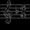
The Swedish mathematician Helge von Koch came up with this curve back in 1904. It is obtained by dividing the segment into three parts and replacing the middle segment with an equilateral triangle without a side coinciding with this segment. The definition is a bit difficult to understand, but the figure is clear and simple.

There are also other varieties of the "Koch curve", but the approximate shape of the curve remains similar.
When Nathan connected the antenna to the radio receiver, he was very surprised - the sensitivity increased dramatically. After a series of experiments, the future professor at Boston University realized that an antenna made according to a fractal pattern has a high efficiency and covers a much wider frequency range compared to classical solutions. In addition, the shape of the antenna in the form of a fractal curve can significantly reduce the geometric dimensions.
Nathan Cohen even developed a theorem proving that to create a broadband antenna, it is enough to give it the shape of a self-similar fractal curve. The author patented his discovery and founded a firm for the development and design of fractal antennas Fractal Antenna Systems, rightly believing that in the future, thanks to his discovery, cell phones will be able to get rid of bulky antennas and become more compact. 
Basically, that's what happened. True, to this day, Nathan is in a lawsuit with large corporations who illegally use his discovery to produce compact communication devices. Some well-known manufacturers mobile devices, such as Motorola, have already reached a peace agreement with the inventor of the fractal antenna.
PS: Anticipating the questions that have arisen on this topic, I assume that such antennas do not work as efficiently. Physics and nature cannot be deceived. Any twisting and reduction in the size of antennas causes a decrease in its efficiency. Such antennas and systems of them can be used at sufficiently high frequencies and, if desired, their miniaturization. This is already finding its way into cell phones, chip resonators, printed circuit boards etc.
High efficiency cannot be expected here, but they will work in cramped conditions and are already working.
Answers to questions from the forum, guestbook and mail.
The world is not without good people:-)
Valery UR3CAH: "Good afternoon, Egor. I think this article (namely, the section "Fractal antennas: less is better") corresponds to the theme of your site and will be of interest to you:) Is it true? 73!"
Yes, of course it's interesting. To some extent, we have already touched on this topic when discussing the geometry of hexabims. There, too, there was a dilemma with the "packing" of the electrical length into geometric dimensions :-). So thank you, Valery, very much for the material sent.
"Fractal antennas: less is better, but better
Over the past half century, life has changed rapidly. Most of us take the advances in modern technology for granted. Everything that makes life more comfortable, you get used to very quickly. Rarely does anyone ask the questions “Where did this come from?” and "How does it work?". The microwave oven warms up breakfast - well, great, the smartphone allows you to talk to another person - great. This seems like an obvious possibility to us.
But life could be completely different if a person did not look for an explanation for the events taking place. Take, for example, cell phones. Remember the retractable antennas on the first models? They interfered, increased the size of the device, in the end, often broke. We believe that they have sunk into oblivion forever, and partly because of this ... fractals.
Fractal drawings fascinate with their patterns. They definitely resemble images of space objects - nebulae, galaxy clusters, and so on. Therefore, it is quite natural that when Mandelbrot voiced his theory of fractals, his research aroused increased interest among those who studied astronomy. One such amateur named Nathan Cohen, after attending a lecture by Benoit Mandelbrot in Budapest, was inspired by the idea of practical application of the knowledge gained. True, he did it intuitively, and chance played an important role in his discovery. As a radio amateur, Nathan sought to create an antenna with the highest possible sensitivity.
The only way to improve the parameters of the antenna, which was known at that time, was to increase its geometric dimensions. However, the owner of Nathan's downtown Boston apartment was adamantly opposed to installing large rooftop devices. Then Nathan began to experiment with various forms of antennas, trying to get the maximum result with the minimum size. Fired up with the idea of fractal forms, Cohen, as they say, randomly made one of the most famous fractals out of wire - the “Koch snowflake”. The Swedish mathematician Helge von Koch came up with this curve back in 1904. It is obtained by dividing the segment into three parts and replacing the middle segment with an equilateral triangle without a side coinciding with this segment. The definition is a bit difficult to understand, but the figure is clear and simple.
There are also other varieties of the "Koch curve", but the approximate shape of the curve remains similar.  When Nathan connected the antenna to the radio receiver, he was very surprised - the sensitivity increased dramatically. After a series of experiments, the future professor at Boston University realized that an antenna made according to a fractal pattern has a high efficiency and covers a much wider frequency range compared to classical solutions. In addition, the shape of the antenna in the form of a fractal curve can significantly reduce the geometric dimensions. Nathan Cohen even developed a theorem proving that to create a broadband antenna, it is enough to give it the shape of a self-similar fractal curve.
The author patented his discovery and founded the company for the development and design of fractal antennas Fractal Antenna Systems, rightly believing that in the future, thanks to his discovery, cell phones will be able to get rid of bulky antennas and become more compact. Basically, that's what happened. True, to this day, Nathan is in a lawsuit with large corporations that illegally use his discovery to produce compact communication devices. Some well-known mobile device manufacturers, such as Motorola, have already reached an amicable agreement with the inventor of the fractal antenna."
Despite the seeming "unreal and fantastic", the situation with the increase in the useful signal is absolutely real and pragmatic. You do not have to be seven spans in the forehead to guess where the extra microvolts come from. With a very large increase in the electrical length of the antenna, all its broken sections are located in space in phase with the previous ones. And we already know where the gain comes from in multi-element antennas: due to the addition of energy in one element re-radiated by other elements. It is clear that they cannot be used as directional ones for the same reason :-) it is impossible, but the fact remains: a fractal antenna is really more efficient than a straight wire.
- Back
- Forward
You have no rights to post comments
Duchifat: really 9 milliwatts?
 With the new antenna, the Israeli Duchifat-1 began to receive noticeably better. It is always heard weakly, but it seems to be better with a stack of two 7-element antennas. Received a couple of frames of telemetry. It's a bit scary, I'm afraid it's my decoder that's not correct. Or an inaccurate "translation" of the package numbers into parameters from DK3WN. In the package, the power from the sensor (forward) is only 7.2 milliwatts. But if he tells the truth, then 10 milliwatts of his power on Earth can be heard perfectly :-)
How beautiful this world is, look
 Just sat at the same table with the whole world. The passage spoils the equality of microvolts from all directions. The same thing I wrote yesterday and the day before yesterday. Who goes to visit me for a long time, already read. And listened. Below is a soundtrack of three interesting QSOs made with an interval of 5-7 minutes. There were still connections between them, but not so expressive, Japanese, Americans .... They can no longer be called DXs because of their large number :-)
So for the unbelievers, three audios one after the other 9M2MSO, Malaysia, Puerto Rico NP4JS and finally the charming Cecile from Venezuela YY1YLY. I am grateful to the Almighty for the fact that we are so different, colorful, cool and interesting. All connections are like SSB selection. as if specifically for too, so that everyone can listen .... :-)
Successful survivor
The successful DelfiC3 flew with its 125 milliwatts, it is perfectly audible, it is decoded with Java lotion RASCAL perfectly and sends the received lines to the site of the support team. AUDIO - Decoder picture below.

Lost WEB receiver?
 We just had time to talk about the Java machine, when SUN slipped us another pig :-) Of course, everything is for the benefit of the user. Only they forgot that it is necessary to notify the millions of users of WEB receivers about the tightening of security requirements, which in 90 percent of cases work through a Java machine. And by the way, not only them. The creators of WED receivers (And, by the way, Windows itself too :-) try to do without JAVA using HTML5 and other twists, but it doesn't always work out. Too long history connects them: everything closes on the features of iron. My laptop, for example, using HTML5 can provide control of the receiver, but cannot receive sound :-) Estimate, the receiver shows everything, but is silent at the same time :-) In short, only Vadim, UT3RZ, will help you today.
"UT3RZ Vadim. Pryluky. http://cqpriluki.at.uaDue to the Jawa update on January 14, 2014 to version 7 Update 51 (build 1.7.0_51-b13), there were problems with listening to WEB SDR receivers. The creators of Jawa, pursuing goals the security of computer users, new version 7 Update 51 introduced the need for user confirmation of security, manually.
Check Your TNC's Ears
Due to boredom, I listened (poked ;-) to the ISS digipeater channel. Rustle quite regularly and quite actively. Audio control, of course, recorded everything. The toad crushed the record. Here I put it, check the settings of your modems or TNC. It's beautiful out there in space. The truth is really boring: the same faces all year round :-(

Telegram UR8RF
Radio Promin

I drink everything. Today, 17 leaf fall, on Radio Promin for 40 hvilin Volodymyr UY2UQ spoke about amateur radio. You can listen to it on the website of Radio Promin in the audio archive of 17 leaf fall.
Hour 15:14:14 - 15:54:38 http://promin.fm/page/9.html?name=Audioarhiv1http://promin.fm/page/9.html?name=Audioarhiv1
73! With respect Oleksandr UR8RFInternet goes to Morse
In December 2011 Google announced the release Gmail apps for iOS, which allows you to quickly take small notes. In a company press release, it was noted that even cavemen used such records, making drawings on the rocks. And now the software for quick notes received its logical continuation - Google announced a fundamentally new way of typing on the keyboard of mobile devices.
Gmail Tap is the name of the application with which the transition from the usual 26-key smartphone keyboard to a two-button one will become a reality. You heard right. From now on, users of both iOS and Android devices will be able to use Gmail Tap to type text messages using only two buttons - a dot and a dash. Google experts, led by Reed Morse (the great-great-grandson of the famous inventor of Morse code), offer users a simplified version of Morse Code, with which SMS messages can be typed no slower than with a standard keyboard. The ability to type two messages at the same time is admirable. The mode for advanced users "multi email mode" involves the use of two keyboards - a standard one at the bottom and an additional one at the top of the screen. And even a novice Gmail Tap user can quickly learn how to type without looking at the keyboard. See how easy it is: