General Provisions.
The contact or classic battery ignition system (Figure 75) consists of an ignition switch, an ignition coil, an additional resistor, an interrupter-distributor, spark plugs, high voltage and low voltage wires.
The principle of operation of the ignition system is as follows:
When the ignition switch is off and the breaker contacts are closed, the current from battery passes through the primary winding of the ignition coil and creates an electromagnetic field in it.
When the crankshaft is turned, the breaker cam clutch opens the contacts. The current in the circuit is interrupted. The magnetic field, disappearing, crosses the turns of the secondary winding. A high voltage pulse is induced in it, which is supplied by the distributor to the spark plugs.
Contact ignition systems can be installed on UAZ-469, GAZ-66, ZIL-131, Ural-375 vehicles.
Fig. 75. Schematic diagram contact ignition system
The device of the devices of the contact ignition system.
Ignition coil.
Serves for converting low voltage to high voltage. It consists of a core, primary and secondary windings, a magnetic circuit, an insulator, a cover with terminal clamps and a housing, in accordance with Figure 76.
The coil is an autotransformer, on the iron core of which the secondary winding is wound, and on top of it is the primary winding. The secondary winding is wound with a PEL wire with a diameter of 0.06 to 0.1 mm with the number of turns from 18000 to 43000. The primary winding is wound with a wire with a diameter of 0.57-0.77 with the number of turns from 185 to 530.
The core with windings is housed in a sealed steel casing and secured in it with an insulator and a cover. All empty spaces in the coil body are filled with transformer oil, which improves the insulation of the windings and the heat transfer from them to the body.
Fig. 76. Ignition coils:
a) Unshielded with b) shielded (B102-B).
additional resistor (B13)
The ignition coils of military vehicles differ from each other in winding data, the number of terminal clamps and the presence of shielding.
Additional resistor.
An additional resistor is used to ensure the normal thermal regime of the ignition coil. It installs the coil mounting brackets (B13) between the legs or is performed separately (B5A, B102B).
The additional resistor consists of an insulator body, on which a constantan or nickel wire is wound, and output terminals, as shown in Figure 77.
Fig. 77. Additional resistor
When the engine is started by the starter, the voltage at the terminals of the battery is reduced so that this does not cause a decrease in the current in the primary circuit, the additional resistor is shunted by the contacts of the starter relay or the starter traction relay. In addition, at increased engine crankshaft speeds, selection of the resistor value together with the inductance of the primary winding of the ignition coil provides the value U2 ›U (breakdown) in the entire range of rotation frequencies.
Interrupter-distributor of ignition.
Consists of the following mechanisms: an interrupter with a capacitor, a high voltage distributor, centrifugal and vacuum ignition timing controllers and an octane corrector, in accordance with Figure 78.
In the housing, in two bronze bushings, the drive shaft of the chopper cam clutch, the distributor rotor and the centrifugal ignition timing regulator rotates.
The breaker is used to close and open the primary circuit of the ignition system in accordance with Figure 79.
Consists of a plate with a fixed contact, a movable contact lever with a leaf spring, a cam clutch and one or two discs.
Fig. 78. P102 ignition breaker-distributor design:
1 - cam clutch; 2 - rotor; 3 - contact corner; 4 - cover;
Fig. 79. Interrupter with vacuum regulator and octane corrector:
1 - cam clutch; 2 - eccentric screw; 3 - plate with movable contact; 4 - a lever with a movable contact and a leaf spring; 5 - locking screw; 6 - movable disk; 7 - cover of the vacuum regulator; 8 - adjusting washers; 9 - a sealing gasket; 10 - fitting; 11 - tube; 12 - spring; 13 - diaphragm; 14 - regulator body; 15 - thrust; 16 - screw; 17 - axis; 18 - wire
The fixed contact plate is mounted on the axis of the movable contact arm and the eccentric can rotate, changing the gap between the contacts.
The plate is attached to the disc with a locking screw. The drive is secured with screws to the case. If the distributor has a vacuum ignition timing controller, then the contacts are installed on a movable disk, which is placed on a ball bearing of a stationary disk fixed in the housing. The breaker contacts are tungsten.
The cam clutch is installed on the shaft of the distributor shaft. The rotation of the roller is transmitted to it through the weights of the centrifugal ignition timing controller. The clutch opens the contacts with its edges, the contacts are closed under the action of the leaf spring of the lever with a movable contact.
Fig. 80. Capacitor:
1 - clamp; 2 - wire; 3 - washer; 4 - wire; 5 - washer; 6 - butt-end of the plates; 7 - a roll of covers; 8 - conductor; 9 - cable paper; 10 - case; 11 - lacquered; 12 - a thin layer of zinc or tin
The capacitor (figure 80) is connected in parallel with the contacts. It reduces arcing between contacts and increases the rate of flux measurement.
The distributor serves to supply high voltage to the electrodes of the spark plug in accordance with the order of operation of the engine cylinders.
It consists of a cover with a contact carbon and a rotor with a current difference plate. The rotor is mounted on the cam clutch of the breaker.
Sealed distributors (P102) have forced ventilation of the internal cavity of the housing with discharge of spark discharge products into the carburetor suction pipe, in accordance with Figure 81.
Fig. 81. Distributor ventilation diagram:
1.5 - hoses; 2.4 - tubes; 3 - suction pipe of the carburetor;
6 - distributor body
In the distributors of the protected design (P13), ventilation is carried out through the openings in the housing due to the air pressure generated by the slider when the roller rotates.
The vacuum ignition timing regulator is used to change the ignition timing depending on the load on the engine.
It consists of a body, a diaphragm, a spring, a union and a rod, in accordance with Figure 79. The body of the regulator is divided by a diaphragm into two cavities, one of which is connected by a tube to the underhaul space of the carburetor, and the other to the atmosphere. The diaphragm is connected by a thrust to the movable disc of the chopper, on the other hand a spring abuts against it, which counteracts the discharge in the carburetor. Shims are installed under the spring from the side of the union.
When working at low loads, the vacuum in the mixing chamber is large, it is transmitted to the diaphragm. The diaphragm bends, compresses the spring and, through the rod, turns the movable disk with contacts against the direction of rotation of the roller, while the lead angle increases.
With an increase in the load, the vacuum in the mixing chamber drops and the spring, through the rod, turns the disk in the direction of rotation of the roller, reducing the ignition timing.
The vacuum regulator provides a change in the ignition moment from 0 to 13˚ according to the angle of rotation of the distributor roller. The centrifugal timing adjuster is used to change the ignition timing depending on the crankshaft speed.
Consists of two weights and two springs, in accordance with Figure 82. The weights are installed on the axes of the roller flange, and with their fingers entering the cutouts of the cam clutch drive plate.
The centrifugal regulator comes into operation at 400 rpm. In this case, the weights diverge under the action of centrifugal forces, stretching the springs.
The fingers of the weights, moving along the rectangular cutouts of the driver plate, turn the cam clutch and the distributor rotor in the direction of rotation of the roller. At the same time, the lead angle increases. When the frequency of rotation of the distributor roller decreases, the springs are compressed and through the weights they turn the cam clutch in the opposite direction, reducing the ignition timing.
The centrifugal regulator provides a change in the ignition timing in the range from 0 to 20˚.
Fig. 82. Centrifugal ignition timing controller:
1 - cam clutch; 2 - driving plate; 3 - weight; 4 - finger;
5 - spring; 6 - roller; 7 - traverse; 8 - weight axis; 9 - weight
The octane corrector is used to change the initial angle of the ignition timing, depending on the type of fuel used and operating conditions, and provides rotation of the distributor housing.
The octane corrector provides an angle variation within ± 12 °.
Spark plug.
They serve to ignite the working mixture in the engine cylinders.
The candle, in accordance with figure 83, consists of a body with a side electrode, an insulator, a center electrode, a contact device and sealing parts.
The insulator is made of uralite, boron corundum, sinoxal or hilumin.
The central electrode in the insulator is sealed with thermal cement or glass-based silicon or copper.
Center electrode material - nickel-manganese alloy or chrome-titanium steel. Marking is made on the cylindrical part of the candle.
Fig. 83 Spark plugs:
1 - wire tip; 2 - rod; 3 - insulator; 4.12 - body; 5 - central electrode; 6.10 - side electrode; 7.11 - sealing ring; 8 - washer; 9 - conductive sealant; 13 - screen; 14 - suppression resistor; 15.17 - ceramic sleeve; 16 - high voltage wire; 18 - rubber bushing; 19 - nut; 20 - bushing; 21 - wire shield
Consider an example of marking spark plugs M8T, A11H, A17DV.
The letters M and A denote the thread M-18x1.5; A-14x1.25; numbers 8, 11 and 17 - the magnitude of the glow number. Letters H and D - the length of the threaded part of the candle body; H-11mm; D-19mm; the letter B indicates that the lower cone of the insulator protrudes beyond the candle body; letter T - the central electrode is sealed with thermal cement.
If there are no letters H and D in the marking of the candle, then such a candle has a thread length of 12 mm, if there is no letter T, the sealing of the central electrode in the insulator is made with glass sealant, if there is no letter B, the insulator does not protrude beyond the candles.
Ignition and starter switch.
Serves to turn on and off the primary circuit of the ignition system, starter, instrumentation and other circuits.
Consists of a body, a locking device, in accordance with figure 84.
It has 4 terminals AM, KZ and ST, PR, connected respectively to the ammeter, ignition coil of the starter relay, and the receiver.
Figure 84 shows the terminal connection diagram for different positions of the ignition key.
Fig. 84. Ignition switch
The action of the contact ignition system.
Let's consider the operation of the ignition system according to the diagram in accordance with Figure 85.
With the ignition on and the breaker contacts closed, a low voltage current will flow in the primary circuit.
Current path: positive battery terminal - ammeter - ignition switch - additional resistor - radio interference filter - primary winding of the ignition coil - low voltage terminal of the distributor - closed contacts - housing - negative battery terminal.
Electromagnetic energy is stored in the ignition coil. When the crankshaft rotates with the starting handle, the contacts open under the action of the cam clutch.
The primary winding circuit is interrupted and a self-induction EMF of about 300 volts is induced in it. In the secondary winding, an EMF of mutual induction up to 20 thousand volts or more is induced.
Fig. 85. Contact ignition system diagram
High voltage circuit: secondary winding - central socket of the distributor cover - contact coal - current difference plate of the slider - side electrode of the cover - central electrode of the candle - side electrode of the candle - body - negative battery terminal and further along the section of the low voltage circuit to the secondary winding.
The self-induction EMF of the primary winding charges the capacitor. The capacitor is discharged through the primary winding during the open state of the contacts, accelerating the disappearance of the magnetic flux and increasing the duration of the spark discharge between the spark plug electrodes.
When the engine is started with a starter, the contact disk of the starter traction relay CT130 shorts the additional resistor.
When the engine is running at medium and high engine speeds, the primary circuit is supplied by the generator set.
With a change in the load on the engine, the vacuum ignition timing regulator comes into operation, acting on the contacts of the breaker. With a change in the speed of the crankshaft, the centrifugal ignition timing regulator comes into operation, acting on the cam clutch of the chopper. Thus, when the vacuum regulator is working together, the ignition timing of the engine is determined by the algebraic summation of the values of these angles and the setting angle of the ignition timing.
To stop the engine, you must turn off the ignition. In this case, the primary circuit is interrupted.
Send your good work in the knowledge base is simple. Use the form below
Students, graduate students, young scientists who use the knowledge base in their studies and work will be very grateful to you.
Posted on http://www.allbest.ru/
Introduction
In the first engines (for example, the Daimler engine, as well as the so-called semi-diesel), a mixture of fuel and air was ignited at the end of the compression stroke from a red-hot glow head - a chamber communicating with the combustion chamber (synonym - glow tube). Before starting, the glowing head had to be heated with a blowtorch, then its temperature was maintained by the combustion of fuel when the engine was running. At present, glow engines used in various models (aircraft, auto, ship models) work according to this principle. In this case, glow ignition wins with its simplicity and unsurpassed compactness.
Diesel engines also do not have an ignition system, the fuel is ignited at the end of the compression stroke from the air that is very hot in the cylinders.
Compression carburetor engines do not need an ignition system, the air-fuel mixture is ignited by compression. These engines are also used in modeling.
But the spark ignition system has really taken root on gasoline engines, that is, a system whose distinctive feature is the ignition of the mixture with an electric discharge that breaks through the air gap between the spark plug electrodes.
Currently, there are three ignition systems: using a magneto, battery ignition with a car battery, and a battery-free ignition system using a motorcycle alternator.
It can be distinguished: circuits without the use of electronic components ("classic") and electronic.
In my thesis, the classic contact ignition system is considered.
The contact ignition system is the oldest type of ignition system. Currently, this system is used on some models of domestic cars (the so-called "classic"). The creation of high voltage and its distribution among the cylinders in this system occurs with the help of contacts.
1. The device of the contact ignition system
1.1 Purpose of the contact ignition system
The ignition system is a combination of all devices and devices that provide the appearance of an electric spark that ignites the fuel-air mixture in the cylinders of an internal combustion engine at the right time. This system is part of common system electrical equipment. The ignition system serves to ignite the working mixture in the engine cylinders at strictly defined moments. Ignition of the mixture can be carried out by a battery ignition system or from a magneto. The vehicles under study use a battery ignition system. According to the method of interrupting the primary circuit current, battery ignition systems are divided into contact, contact-transistor and non-contact transistor. Until 1960, cars were mainly equipped with a contact ignition system. Currently, transistor ignition systems are increasingly used, especially on eight-cylinder engines.
1.2 The principle of operation of the contact ignition system
Ignition system
The ignition system is used only in gasoline and gas engines. With its help, the air-fuel mixture that has got into the engine cylinders is ignited at a strictly defined point in time. The ignition of the mixture inside the cylinder occurs when a spark forms between the electrodes of the spark plug when a current of 18,000-20,000 V is applied to it.
There are three types of ignition systems:
Contact,
Contactless and
· Microprocessor.
The contact system is not used on modern cars. However, it was previously widespread. Let's give it its due, as it has served faithfully for many years, and consider its fundamental structure. The principle of operation is based on the law of electromagnetic induction. From the battery with the ignition on and the breaker contacts closed, a low voltage current flows through the primary winding of the ignition coil, forming a magnetic field around it. Opening the breaker contacts leads to the disappearance of the current in the primary winding and magnetic field around her. The disappearing magnetic field induces a high voltage (about 20-25 kilovolts) in the secondary winding. The distributor alternately supplies high-voltage current to the high-voltage wires and spark plugs, between the electrodes of which a spark charge jumps, the fuel-air mixture in the engine cylinders ignites.
The disappearing magnetic field crosses not only the turns of the secondary, but also of the primary winding, as a result of which a self-induction current of about 250-300 volts arises in it. This leads to arcing and burning of the contacts, in addition, the interruption of the current in the primary winding is slowed down, which leads to a decrease in the voltage in the secondary winding. Therefore, a capacitor is connected in parallel to the contacts of the breaker (as a rule, with a capacity of 0.25 μF).
An additional resistance (or an additional resistor) is connected in series with the primary winding of the ignition coil. At low speeds, the contacts of the breaker are most of the time in a closed state and a current flows through the winding, more than enough to saturate the magnet-wire. Excessive current unnecessarily heats up the coil. When the engine is started, the additional resistance is shunted by the contacts of the starter relay, thereby increasing the energy of the electric spark on the spark plug. The principle of operation of the contact ignition system
When the breaker contact is closed, a low voltage current flows through the primary winding of the ignition coil. When the contacts are opened, a high voltage current is induced in the secondary winding of the ignition coil. The high-voltage wires are supplied to the distributor cover, from which it is distributed over the corresponding spark plugs with a certain ignition timing.
With an increase in the speed of the engine crankshaft, the speed of the distributor chopper shaft increases. The weights of the centrifugal ignition timing regulator diverge under the action of centrifugal force, moving the movable plate with the breaker cams. The breaker contacts open earlier, thereby increasing the ignition timing. With a decrease in engine speed, the ignition timing decreases.
A further development of the contact ignition system is the contact transistor ignition system. In the circuit of the primary winding of the ignition coil, a transistor switch is used, controlled by the contacts of the breaker. In this system, due to the use of a transistor switch, the current in the primary winding circuit is reduced, thereby increasing the service life of the breaker contacts.
Scheme 1.2.1
1. Turns the ignition key to allow low voltage current from the battery to flow to the primary coil of the ignition coil.
2. When a current appears on the primary winding, a magnetic field arises.
3. The contacts of the breaker open, due to the cranking of the engine, which is initially driven by the starter.
4. The low voltage current and the magnetic field, which induce a high voltage current to the secondary winding, disappear.
5. The generated high voltage current flows to the central terminal of the ignition coil, and from there to the distributor cover.
6. At the distributor, the current is distributed to each spark plug.
7. The current appearing on the candle forms a spark discharge between the electrodes, which ignites the fuel-air mixture.
Self-induction current appears not only on the secondary, but also on the primary winding, which leads to burning of the contacts and arcing. It is also possible to interrupt the current in the primary winding, which reduces the voltage in the secondary. To reduce the effect, a capacitor connected in parallel to the contacts of the breaker is used.
Diagram 1.2.2 of a classic contact ignition system:
1 - battery; 2, 3 - contacts of the ignition switch; 4 - additional resistor; 5 - ignition coil; 6 - breaker; 7, 8 - movable and fixed contacts of the breaker; 9 - cam; 10 - distributor; 11 - rotor (slider); 12 - stationary electrode; 13 - spark plugs; 14 - capacitor.
1.3 Devices of the contact ignition system
ignition system engine
The design features of the devices of the contact ignition system are as follows.
The contact ignition system consists of the following elements: a power supply, an ignition switch, a mechanical low voltage circuit breaker, an ignition coil, a mechanical high voltage current distributor, a centrifugal ignition timing controller, a vacuum ignition timing controller, spark plugs and high voltage wires.
The mechanical breaker is designed to open the low voltage circuit (primary circuit of the ignition coil). When the contacts are opened, a high voltage is induced in the secondary circuit of the ignition coil. To protect the contacts from burning, a capacitor is included in the circuit parallel to the contacts.
The ignition coil is used to convert low voltage current into high voltage current. The coil has two windings - low and high voltage.
The mechanical distributor ensures the distribution of high voltage current through the spark plugs of the engine cylinders. The distributor consists of a rotor (the common name is "slider") and a cover. The cover has central and side contacts. The center contact is supplied with high voltage from the ignition coil. The high voltage is transmitted through the side contacts to the corresponding spark plugs.
The chopper and distributor are structurally combined in one housing and are driven from the engine crankshaft. This device has a common name interrupter-distributor (common name - "distributor").
The centrifugal ignition timing regulator is used to change the ignition timing depending on the number of revolutions of the engine crankshaft. Structurally, the centrifugal regulator consists of two weights. The weights act on the movable plate on which the breaker cams are located.
The ignition timing is the angle of rotation of the engine crankshaft at which a high voltage current is supplied to the spark plugs. In order for the fuel-air mixture to completely and efficiently burn out, the ignition is carried out ahead of time, i.e. until the piston reaches top dead center.
The ignition timing is set by adjusting the position of the distributor in the engine.
The vacuum ignition timing regulator provides a change in the ignition timing depending on the load on the engine. The engine load is determined by the throttle valve opening (gas pedal position). The vacuum regulator is connected to the cavity behind the throttle valve and, depending on the degree of vacuum in the cavity, changes the ignition timing.
The high voltage wires carry high voltage current from the ignition coil to the distributor and from the distributor to the spark plugs.
The spark plug is designed to ignite the fuel-air mixture by generating a spark discharge.
1.3.1 Devices of the contact ignition system
1.3.2 Diagram of ignition elements on a Moskvich (AZLK) 2140 car
Description of the elements of the ignition system
1 Drive clutch.
2 Cam plate.
3 Oil can spring.
4 Oiler.
5 Condenser.
6 Distributor housing.
7 Low voltage terminal.
8 Cam.
9 Distributor cover.
10 Slider.
11 Slider contact plate
12 Spring of contact coal.
13 Contact ember.
14 Cam seal.
15 Spring for fastening the distributor cover.
16 Spring of the centrifugal regulator.
17 Weight of the centrifugal regulator.
18 Bearing.
19 Distributor roller with plate.
20 Cam Filtz.
21 Fixed interrupter plate.
22 Draft of the vacuum regulator.
23 Vacuum regulator.
24 Movable breaker plate.
25 Fixed contact.
26 Terminal block fixing screw.
27 Contact rack.
28 Breaker lever.
29 High voltage wire.
30 Rubber cap.
31 Linen core.
32 Insulation.
33 Conductor.
34 Wire end.
35 Diaphragm of the vacuum regulator.
36 Spring of the vacuum regulator.
37 Spark plug tip body.
38 Contact terminal.
39 Spring clip.
40 Side electrode.
41 Center electrode.
42 Heat dissipating washer.
43 Gasket.
44 Candle body.
45 Insulator.
46 Glass sealant.
47 Contact bar.
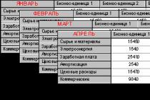
1.4 Specifications ignition systems Moskvich 2140
Rated supply voltage - 12 ± 0.2V
Allowable voltage variations - from -7.8 to +18.2 V
The amplitude of the voltage developed in the primary circuit of the short circuit - ± 500 V
Average current consumption, no more - 2.5 A
Consumption current at 600 ± 60 rpm of the distributor shaft - 0.4 A
Consumption current at 4000 ± 400 rpm of the distributor shaft - 4.5 A
Consumption current through the breaker contacts, no more - 0.3 A
2. T.O. and repair of the contact ignition system
2.1 Organization of the workplace of a car repair mechanic
The main workplace of a car mechanic outside the posts and lines of maintenance and repair is a post equipped with a locksmith's workbench, where assemblies and devices removed from the car are disassembled and assembled and perform fitting and fitting and other work.
The lid of the workbench is upholstered with thin sheet (roofing) steel, which protects it from damage and makes it easier to keep it clean.
Before starting work, the car mechanic must prepare all the tools and accessories necessary for its implementation and correctly position them on the workbench.
Keeping tools and devices in good condition and following the rules for using them is important. For the convenience of work, the vice should be fixed on the workbench at a certain height, depending on the height of the worker. The vise is set correctly if the hand of the worker, resting his elbow on the jaws of the vise, touches the chin with the tips of his fingers.
Hammers must be firmly attached to the hardwood handles.
The end of the working part of chisels and crossheads must be sharpened well at a certain angle. Burrs should be removed from the upper end of the chisel, cross cutter, as well as the barb and punch, which, flying off when hammering, can injure.
Wooden file handles must be reinforced with metal rings that protect the handles from splitting and allow them to fit more tightly onto the file shanks.
When preparing a hacksaw for work, it is necessary to correctly (the teeth of the hacksaw should be directed forward) to install the blade in the hacksaw and tighten the thumbs well so that the blade does not bend during cutting.
When performing work directly at the car, the workplace of a car mechanic is a maintenance or repair station.
Both when performing work on a workbench and directly at the car, its organization is important.
Before starting work, the car mechanic must receive an order for its implementation. The attire indicates what work needs to be done, the time limit and the price. The spare parts or materials required to complete the work are discharged from the warehouse.
If you need to make new part to the car mechanic himself, he is given a drawing or a sample of the part. Having received a task (outfit) for work, a car mechanic must first of all prepare the tools, devices and materials necessary to complete the task, and place them correctly on a workbench or near a car.
Each instrument must be placed in a specific place so that any object can be taken immediately, without making unnecessary movements and without spending too much time looking for it. It is advisable to train yourself to take the instrument without looking.
Instruments that are taken with the left hand are placed on the left, and those that are taken with the right hand are-- on right. Everything that they use more often is closer to themselves. Items not related to the work being performed are removed from the workbench.
Job responsibilities
An auto electrician is obliged to:
1. Get to work 10 minutes before the start of the working day, change into clean overalls, prepare workplace to work.
2. Carry out the repair of electrical equipment and diagnostics of the vehicle, according to the assignment received from the shift master:
Diagnose electrical equipment using an existing computer to diagnose the generator and engine;
Carry out, if necessary, disassembly and assembly of electrical equipment to repair the starter;
Put the car on a lift to identify and eliminate chassis malfunctions;
If necessary, disassemble and repair vehicle units to perform gearbox repairs;
Diagnose mechanical engine malfunctions, disassemble and repair the engine;
Hand over the finished car to the shift master.
3. To carry out a complete list of ordered works on the car.
4. In all cases of relationships with customers, act technologically, observing the established standards for the relationship between the employees of the auto center and customers.
5. To prevent the emergence of conflict issues with the customers of the auto center, trying in all cases to meet the requirements of customers and maintain their friendly attitude towards the auto center.
6. Ensure the proper safety of vehicles taken for service.
7. Monitor the working condition of tools and equipment; use them correctly.
8.If any malfunctions are found that affect the safety of vehicle operation, bring this information to the master receiver and the client.
9. Observe safety precautions, fire safety rules, industrial sanitation standards.
10. Take good care of the issued overalls.
11. Ensure the quality of work, rhythm.
2.2 Tools and devices used in the maintenance and repair of the contact ignition system
To work with car wiring, you need a high-quality auto electrician tool and instruments for testing and diagnosing electrical equipment and batteries.
Measuring probe - a tool for measuring very small distances by contact method, which is a set of thin metal plates of various thicknesses with a size applied to them (plate thickness). The plates of the set are introduced into the gap until the next thickest plate ceases to fit into the measured gap.
Measuring probes flat
Flat measuring probes are used to control the gaps between the planes.
The probe looks like a plate of a certain thickness.
Measuring probes are manufactured with a thickness of 0.02 to 1 mm.
The measuring probes are produced as sets of measuring plates of different thickness in one holder.
Styli can be used individually or in various combinations.
Technical characteristics of flat measuring probes:
|
No. of stylus plates |
|||||
|
nominal thickness, mm |
|||||
Fig 2.2.2 Electrical probe for checking electrical circuits on a car, for 6-12 and 24 V.
With test tip, protective cap, crocodile grip cable.
Length 120 mm
Fig 2.2.3 Pliers
Fig 2.2.4 Combination wrenches
Fig 2.2.5 Screwdriver set
How efficiently and safely a screwdriver works every day depends primarily on the quality of the tool. Not only the use of high quality materials, but the very shape of the instrument is of particular importance to ensure that the hand always has a strong grip on the instrument.
Fig 2.2.6 Auto electrician set 226 items
1 - Wire stripper and crimping pliers 5 func. 225mm (TCP-10353)
1 - Phillips screwdriver VDE PH1 x 80 mm
1 - Slotted screwdriver VDE SL0,8 x 4,0 x 80 mm
1 - Probe 6-12-24V
1 - Fuse remover
1 - A brush for battery terminals
Fuse set - 5A, 7.5A, 10A, 15A, 20A, 25A, 30A
Fuse set 6,35 * 32 mm (glass) - 5A, 10A, 15A
Fuse kit Euro - 8A, 10A, 16A
1 - Insulating tape 19 mm x 9 m
1 - Wire 1.25 mm² x 1.5 m
Set of terminals (fork, ring, bayonet)
Set of heat shrinkable connecting sleeves
Set of heat shrink sleeves - W10 x 50mm, W5 x 50mm, W3 x 50mm
Set of plastic clamps - 2.5 x 100 mm, 2.5 x 160 mm, 3.6 x 200 mm
9 - Automotive lamps
1 - Wire with crocodile clips
Qty per box: 12 pcs; Net weight: 1.11kg; Gross weight: 1.9kg; Volume: 0,005 мі
Fig 2.2.7 Multitestor
2.3 List of work performed in the scope of daily maintenance (ETO), TO-1, TO-2 for the contact ignition system
Maintenance elements of ignition systems (interrupter-distributor, coil, switch and spark plugs) are carried out during each next TO-2 of the car with in-depth diagnostics of the technical condition.
During daily maintenance and TO-1 check the serviceability of the ignition switch, the reliability of electrical contacts, the condition of high-voltage wires and their insulation, the fastening of all ignition devices. It is necessary to systematically lubricate the bearings of the drive shaft, the parts of the centrifugal ignition timing regulator, the axis of the movable contact and the cam clutch, and the felt wick of the cam.
In the contact ignition system, the contacts of the breaker burn and erode, which increases the resistance in the primary circle of the induction coil and reduces the angle of the closed state of the contacts. To eliminate these shortcomings, you should promptly clean them from carbon deposits and dirt and adjust the gap between them.
During operation, keep the high-voltage parts of the ignition system clean and prevent moisture, dust and dirt from entering them, which can lead to partial shunting and loss of current, breakdown of high-voltage parts or surface overlap.
Spark plugs are unscrewed during TO-2 with a special wrench, pre-cleaning the socket with compressed air, and check the absence of cracks and carbon deposits on the insulator. The size of the gap between the electrodes is checked with a round probe and adjusted by bending the side electrode.
It is forbidden to burn out the spark plugs, since microcracks appear on the insulator, which leads to a deterioration in performance and the failure of spark plugs.
During maintenance, you should check whether the wires that connect to the terminals of the ignition coil, additional resistance and transistor switch, which can damage the latter, are not reversed.
2.4 Possible malfunctions of the ignition system
|
No spark |
||
|
1). Defective ignition distributor |
Find the cause and fix the problem. |
|
|
2). Defective ignition coil |
Replace with a new one. |
|
|
3). Defective ignition switch |
Check the lock and replace the contact device of the lock. |
|
|
4). The candles are out of order |
Clean or replace plugs. |
|
|
Interruptions in engine operation |
||
|
1). Distributor defective |
Check and repair the damage. |
|
|
2). Poor contact in the primary circuit |
Eliminate the defect. |
|
|
4). Ignition coil defective |
Check or replace. |
|
|
5). Cracks in the distributor cap |
Replace cover. |
|
|
6). Dirt or moisture on the distributor cover contacts or wires |
Clean and dry contacts or wires. |
|
|
7). Incorrect contact gap |
Adjust the clearance (0.35-0.45mm). |
|
|
eight). Capacitor broken |
Replace. |
|
|
nine). Defective spark plug: oily or burnt electrodes, incorrect gap size, cracks in the insulator |
Check the spark plugs with the engine running. Unscrew the defective plug and clean it from carbon deposits. Replace the spark plug with a crack in the insulator. |
|
|
Interruptions in one of several engine cylinders |
||
|
1). Burning and contamination of breaker contacts |
Eliminate the defect. |
|
|
2). Violation of the gap between the contacts of the breaker |
Set the gap between 0.35-0.45 mm. |
|
|
3). High voltage wires loose or damaged |
Reconnect or replace wires. |
|
|
The engine suddenly stops working and cannot be started |
||
|
1). Capacitor broken |
Check and fix the defect. |
|
|
2). Lost contact in the ignition supply circuit |
Inspect the places of the wire contacts. |
|
|
The engine runs only when starting until the starter is turned off |
||
|
1). Open in the additional resistor of the ignition coil |
Replace the resistor. |
2.5 Setting the ignition timing
Fig 2.5.1 Distributor (with slider and cover removed) for engine mod. 331 and 3317
Fig 2.5.2 Duplicate alignment marks on the flywheel and clutch housing of the engine mod. 331 and 3317
Installation of ignition on engines mod. 331 and 3317 are produced with a new car running 1.5 thousand km. and then every 15 thousand km.
On engines mod. 331 and 3317, ignition distributors 47.3706 are installed.
Checking the working surface of the breaker contacts, cleaning them, lubricating the distributor are carried out similarly to the engine ignition distributor mod. 2106 every 15 thousand km of the car's run. Additionally, it is necessary to lubricate the cam bushing by first removing the rotor and the felt washer under it.
Adjusting the gap between the breaker contacts
1. Turn the distributor shaft so that the gap between the contacts becomes the largest.
2. Loosen the screws 3 (Fig. Distributor (with the slider and cover removed) of the engine models 331 and 3317) fastening the contact rack 8.
3. Insert a screwdriver into the groove 9 and, approaching (or removing) the contact post 8 to (from) contact (a) on the breaker lever 1, set the gap between the contacts to 0.45 ± 0.05 mm.
4. After completing the adjustment, tighten the screws 3.
Setting the ignition timing for options:
A) The distributor was not removed from the engine
1. Remove the distributor cover.
2. Rotating the crankshaft, bring the runner's current-carrying plate to the low-voltage terminal of the distributor (to the high-voltage terminal to the spark plug of the first cylinder on the distributor cover).
3. Continuing to slowly rotate the crankshaft, align mark 3 on the crankshaft pulley with the locating pin 1 on the lower cover of the camshaft sprockets (duplicate mark 3 (Fig. Adjusting duplicate marks on the flywheel and clutch housing of the engine mod. 331 and 3317) on the flywheel should match with locating lug 2 on the clutch housing), the piston of the first cylinder will be in the compression stroke, and the ignition advance will be 10 ° (up to TDC).
4. Connect a test lamp to the low voltage terminal of the distributor 5 (see Fig. Distributor (with the slider and cover removed) (you can use any car lamp) and to ground and turn on the ignition. Turn the distributor housing counterclockwise until the breaker contacts close (the lamp will go out).
5. Press the slider clockwise with your finger and slowly turn the distributor housing in the same direction until the control lamp comes on.
6. Check the accuracy of setting the breaker contacts to open by pressing the cam clockwise and at the same time slightly pressing the lever against it with your finger. In this case, the control lamp will either go out, or the glow of its thread will decrease.
7. Tighten the nut 6 securing the distributor shank to the drive housing.
8. Place the plastic cover on the distributor and secure it with two spring latches.
9. Insert the high-voltage wires from the spark plugs in accordance with the operating order of the engine cylinders and taking into account the direction of rotation of the distributor rotor. Install the tip of the high-voltage wire from the spark plug of the first cylinder in the terminal socket of the distributor cover, located above the low-voltage terminal in the housing.
10. Insert the high-voltage wire from the ignition coil into the center socket of the cover as far as it will go.
B) The distributor was removed from the engine, the crankshaft was turning
1. Unscrew the spark plug of the first cylinder, close the hole for the spark plug in the cylinder head with a crumpled paper plug and rotate the crankshaft until this plug is pushed out, thus defining the start of the compression stroke in the first cylinder.
2. Remove the distributor cover.
3. Rotate the distributor roller to bring the runner's current-spreading plate to the low-voltage terminal.
4. Insert the distributor shank into the distributor drive housing on the engine.
5. Turn the distributor roller by the slider until the pins of the floating clutch align with the roller groove in the distributor drive housing and engage them. It should be borne in mind that the pins of the distributor shaft floating clutch and the mating groove in the drive are offset to the side relative to the axis of symmetry. Therefore, it will not be possible to install the distributor without first turning the slider with the current-spreading plate towards the low-voltage terminal. Further, the ignition is installed in accordance with paragraphs 3-10.
Rotation direction of the ignition distributor rotor 47.3706 for engines mod. 331 and 3317 counterclockwise.
The order of operation of the cylinders of engines 1-3-4-2.
To install an earlier ignition, the ignition distributor housing must be turned clockwise, and a later one - counterclockwise.
Conclusion
The purpose of this thesis is to study the technology of repairing the ignition system.
The thesis consists of an explanatory note and a stand with the installed devices of the contact ignition system.
In the explanatory note of the diploma project, the main part considers:
General description of the ignition system device;
Designs of devices for repair and diagnostics are proposed.
In the special part of the thesis, the following is considered:
Stand with devices connected in low and high voltage electrical circuits;
The main devices intended for the repair of the ignition system are considered.
The topic of this thesis is very relevant, has broad practical and theoretical significance.
The diploma used modern methods study, analysis and systematization of the material.
Consequently, the set goals in the thesis have been achieved.
Posted on Allbest.ru
...Similar documents
Ignition system - a set of devices and devices that ensure the appearance of a spark at the moment corresponding to the order and mode of engine operation. The device of contactless SZ, the main malfunctions and their elimination by the example of the car VAZ-21213 (Niva).
term paper, added 06/14/2009
The device is a contactless transistor ignition system. Checking the main elements of the ignition system on the VAZ-2109. The main advantages of a non-contact transistor ignition system relative to contact systems. Rules for the operation of the ignition system.
abstract, added 01/13/2011
Purpose, design and operation of the ignition system of the ZIL-131 car. The device of the ignition coil, additional resistor, transistor switch, distributor, spark plug. Malfunctions and their elimination, system maintenance.
test, added 01/03/2012
Calculation of reliability indicators of the ignition system using probability theory and mathematical statistics. Purpose and principle of operation of the car ignition system, maintenance, troubleshooting. Study of the main elements of this device.
term paper, added 09/24/2014
Characteristics of the components of the ignition system. HFM control idle adjustment, fault diagnosis. Incremental control, determining the order of injection and ignition. Equation drawing automated system with two cylinders.
term paper, added 05/14/2011
Differences between automotive electronic and microprocessor ignition systems. Non-contact ignition systems with unregulated energy storage time. System operation when different modes engine operation. Electrical diagram injection systems.
test, added 05/13/2009
Scheme, description of work and calculation of parameters of the contact-transistor ignition system. The transformation ratio of the ignition coil. Breaking current at maximum frequency rotation. Inductance of the ignition coil, pulse transformer winding.
term paper, added 07/03/2011
Technical characteristics of cars of the VAZ family. Characteristics of the engine, the device of a contactless ignition system. Setting the ignition timing on cars. Removal and installation of the ignition distributor. Maintenance and repair.
thesis, added 04/28/2011
The principle of operation and the main elements of the contact ignition system, its distinctive features from the transistor, contactless and microprocessor systems. The dependence of the combustion speed on the angle of opening of the throttle valve. Causes of detonation.
abstract, added 06/07/2009
Calculation of the output characteristics of the ignition system, the energy and duration of the spark discharge, the magnitude of the rupture current, the maximum value of the secondary voltage. Conformity assessment of the selected ignition system given parameters automobile engine.
It is ignited by a spark that forms between the electrodes of the spark plug.
For the formation of a spark, a voltage of at least 12-16 kV is required.
The generation of high voltage current, as well as its distribution over the engine cylinders, are carried out by battery ignition devices. The battery ignition system includes a low voltage current source, an ignition coil, a distributor breaker, spark plugs, a capacitor, high and low voltage wires, an ignition switch.
Battery ignition system includes a high voltage circuit and a low voltage circuit. The low voltage circuit is powered by the battery or generator. In addition to current sources, an ignition switch, a breaker, and also the primary winding of the ignition coil with an additional resistor are connected in series to this circuit. All these elements are interconnected by low voltage wires. The high voltage circuit includes: the secondary winding of the ignition coil, high voltage wires, spark plugs, and a distributor.
A high voltage current is generated in the ignition coil. It is based on the principle of self-induction. When the ignition is on and the breaker contacts are closed, the electric current from the generator or from the storage battery is supplied to the primary winding of the ignition coil, as a result of which an electromagnetic field arises around it. When the breaker contacts open, the current in the primary winding disappears, and the magnetic flux around it also disappears. The disappearing magnetic flux crosses the turns of the primary and secondary windings of the ignition coil, as a result of which an EMF arises in each of them. Due to the large number of series-connected turns of the secondary winding, the total voltage at its ends reaches 20-24 kV.
From the ignition coil, the high voltage current flows through the high voltage wires and the distributor to the spark plugs. As a result, an electrical discharge is generated between the spark plug electrodes, which ignites the working mixture in the combustion chambers.
The self-induction EMF in the primary winding of the ignition coil reaches 200-300 V. Due to this, the disappearance of the magnetic flux slows down and a spark appears between the contacts of the breaker. In order to prevent the appearance of a spark between the contacts of the breaker, a capacitor is installed in parallel to the contacts.
Ignition coil converting low voltage current into high voltage current consists of:
1) core;
2) primary winding, which includes 250-400 turns of insulated copper wire with a diameter of 0.8 mm;
3) secondary winding, which includes 19-25 thousand turns of insulated wire with a diameter of 0.1 mm;
4) cardboard tube;
5) an iron case with magnetic circuits;
6) carbolite cover;
7) terminals and an additional resistor.
Secondary winding of the ignition coil is located under the primary winding and is separated from it by a layer of insulating material. The ends of the primary winding are brought out to the terminals of the carbolite cover.
The core of the ignition coil is made of separate strips of transformer steel isolated from each other. This design reduces the generation of eddy currents. The lower end of the core is installed in a porcelain insulator. The inner cavities of the transformation coil are filled with transformer oil.
Additional resistor of the ignition coil consists of a spiral, ceramic sockets and two busbars. The resistance of the additional resistor ranges from 0.7 to 20 ohms. One end of the resistor is connected to the VK terminal using a bus, and the other end is connected to the VKB terminal.
At a low engine speed, the breaker contacts are in a closed state for a long time. As a result of this, the current in the primary circuit increases, the resistor begins to heat up, and a small electric current enters the ignition coil, thereby preventing the coil from overheating.
In order to continuously induce a high voltage current in the secondary winding of the ignition coil, it is necessary to periodically open the primary circuit of the battery ignition system. A breaker is used for this. In addition, the high voltage generated by the ignition coil must be distributed over the engine cylinders in accordance with the order of their operation, this function is performed by the distributor. For more convenient maintenance, as well as to simplify the design of the ignition system, the distributor and the breaker are combined into one device - the breaker-distributor.
Breaker is installed on the car engine and is driven by the camshaft. A thin layer of tungsten is deposited on the contacts of the breaker. The breaker consists of:
1) drive shaft;
2) hulls;
3) movable and stationary discs;
4) centrifugal and vacuum advance controllers;
5) octane corrector;
6) cam with protrusions.
The number of cam lobes is equal to the number of engine cylinders. The cam is connected to the drive shaft through a centrifugal regulator. A capacitor is connected in parallel with the contacts of the breaker, which prevents sparking on the contacts, and also leads to a rapid disappearance of the current in the primary circuit. This increases the voltage in the secondary circuit significantly. The capacitor consists of lacquered paper on which a zinc and tin layer is applied. Such paper is rolled up and serves as a lining of the capacitor. Flexible conductors are soldered to the ends of the roll. The roll is wrapped with cable paper and soaked in oil. The capacitor is mounted on a movable disk or externally on the breaker body.
The capacitance of the capacitor is 0.17-0.2 μF. Metallized paper capacitors can self-repair upon dielectric breakdown by filling the hole with oil.
In addition, the gap between the breaker contacts has a great influence on the operation of the battery ignition system. Normal operation of the battery ignition system is possible with a gap between the breaker contacts in the range from 0.35 to 0.45 mm.
With a large gap, the closed state of the capacitor will decrease, and the current in the primary winding of the ignition coil will not have time to increase to the required value. As a result, the EMF of the secondary circuit will not be high enough. In addition, with a large clearance and a high crankshaft speed, there will be interruptions in the operation of the engine.
With a small gap, strong sparking occurs between the contacts of the breaker, and as a result, interruptions occur in all modes of engine operation. The gap between the breaker contacts is adjusted by moving the plate with the stationary contact post.
The valve is installed on the breaker body and consists of a rotor and a cover. The rotor is made of carbolite and has the shape of a fungus. A contact plate is mounted on the top of the rotor. The rotor is mounted on a cam lip. The distributor cap is also made of carbolite. On the outer part of the rotor cover along the circumference there are sockets according to the number of cylinders. Wires are inserted into the sockets, which are connected to the spark plugs. In addition, a central socket is located in the distributor cover, which is intended for attaching the high voltage wire from the ignition coil. Inside the distributor, opposite each slot are side contacts. In the center of the inner part of the distributor there is a carbon contact with a spring, which is designed to connect the central socket to the rotor plate.
The cover is fixed to the rotor body with two spring latches. The rotor, rotating with the cam, connects the central contact alternately with all the side plane trees, while the high voltage circuit is closed, and the electric current flows into the spark plugs of those cylinders where the working mixture should be ignited at the moment.
Spark plug consists of a central electrode with an insulator, as well as a steel body in which it is attached. The spark plug body has a threaded top that allows the spark plug to be screwed into the threaded hole of the car engine cylinder head. There is one side electrode at the bottom of the housing. In the upper part, the body of the candle has turnkey edges. The central electrode with an insulator is sealed in the candle body. A lug is located on top of the central electrode for attaching a high voltage wire.
For normal work spark plugs, the temperature of the lower part of the insulator must be in the range from 500 to 600 ° C. At this temperature, the carbon burns out, and the candle is cleaned. Excessive heating of the spark plug leads to the destruction of the insulator, and as a result of hypothermia, engine oil and carbon deposits accumulate on the spark plugs.
Even in its first modifications, a car engine was a complex structure consisting of a number of systems working together. One of the main components of any gasoline engine is the ignition system. Today we will talk about its structure, varieties and features.
Ignition system
The ignition system of a car is a complex of devices and devices that work to ensure the timely appearance of an electric discharge that ignites the mixture in the cylinder. It is an integral part of electronic equipment and for the most part is tied to the work of the mechanical components of the motor. This process is inherent in all engines that do not use highly heated air for ignition (diesel, compression carburetor). Spark ignition of the mixture is also used in hybrid engines running on gasoline and gas.
The principle of operation of the ignition system depends on its type, but if you generalize its work, the following stages can be distinguished:
- high-voltage pulse accumulation process;
- charge passage through a step-up transformer;
- synchronization and pulse distribution;
- the appearance of a spark on the contacts of the candle;
- setting fire to the fuel mixture.
An important parameter is the angle or timing of the advance - this is the time at which the air-fuel mixture is ignited. The selection of the moment occurs so that the limiting pressure arises when the piston hits the upper point. In the case of mechanical systems, it will have to be set manually, while in electronically controlled systems, the setting is automatic. The optimal lead angle is influenced by the speed of movement, the quality of gasoline, the composition of the mixture and other parameters.
Classification of ignition systems
Based on the ignition timing method, a distinction is made between contact and non-contact circuits. According to the technology of forming the ignition timing, systems with mechanical adjustment and fully automatic or electronic ones can be distinguished.
Based on the type of charge accumulation, devices with accumulation in inductance and accumulation in capacitance are considered to break through the spark gap. According to the method of switching the primary circuit, the coils are mechanical, thyristor and transistor types.
Ignition system assemblies
All existing types of ignition systems differ in the method of creating a controlling impulse, otherwise their design is practically the same. Therefore, you can specify common elements that are an integral part of any variation of the system.
The power supply is primary, the battery serves (it is used at start-up), and during operation, the voltage that the generator produces is used.
A switch is a device that is necessary to supply power to the entire system or turn it off. The switch is the ignition switch or the control unit.
A charge accumulator is an element necessary to concentrate energy in the required volume, to ignite the mixture. There are two types of accumulation components:
- Inductive - a coil, inside which a step-up transformer is located, which creates a sufficient impulse for high-quality arson. The primary winding of the device is powered by the plus of the battery and comes through the breaker to its minus. When the primary circuit is opened by a breaker, a high-voltage charge is created on the secondary, which is transmitted to the candle.
- Capacitive - a capacitor that charges increased voltage... V the right time the accumulated charge is transmitted to the coil by the signal.

Scheme of work depending on the type of energy storage
Candles are a product consisting of an insulator (candle base), a contact terminal for connecting a high-voltage wire, a metal frame for fastening a part and two electrodes, between which a spark is formed.
Distribution system - a subsystem designed to direct the spark to the desired cylinder. Consists of several components:
- A distributor or distributor is a device that compares the revolutions of the crankshaft and, accordingly, the operating position of the cylinders with the cam mechanism. The component can be mechanical or electronic. The first one transmits the rotation of the motor and, through a special slider, distributes the voltage from the drive. The second (static) eliminates the presence of rotating parts, distribution is due to the operation of the control unit.
- A switch is a device that generates impulses to charge a coil. The part connects to the primary winding and interrupts the power supply, generating a self-induction voltage.
- The control unit is a microprocessor-based device that determines the moment of current transfer to the coil based on the readings of the sensors.
Wire - a single-core high-voltage conductor in isolation, connecting the coil with the distributor, as well as the contacts of the switch with candles.
Magneto
One of the first ignition systems is magneto. It consists of a current generator that creates a discharge solely for sparking. The system consists of a permanent magnet, which is driven by a crankshaft and an inductor. A spark that can break through the spark gap is generated by a step-up transformer, one part of which is the coarse winding of the inductor. To increase the voltage, a part of the generator winding is used, which is connected to the electrode of the candle.

Ignition system with magneto
Control over the spark supply can be contact, made in the form of a breaker, or non-contact. The non-contact sparking method uses capacitors to improve the quality of the spark. Unlike the ignition schemes presented below, magneto does not require a battery, it is lightweight and is actively used in compact equipment - brushcutters, chainsaws, generators, etc.
Contact ignition system
Outdated, common fuel mixture ignition scheme. A distinctive feature of the system is the creation of high voltage, up to 30 thousand V per candles. Such a high voltage is generated by the coil, which is connected to the distribution mechanism. The impulse is transmitted to the coil thanks to special wires connected to the contact group. When the cams open, a discharge and a spark are formed. The device also acts as a synchronizer, since the moment of spark formation must coincide with the desired moment of the compression stroke. This parameter is set by mechanical adjustment and spark shifting to an earlier or later point.

The simplest scheme
The vulnerable part of this option is natural mechanical wear. Because of it, the moment of spark formation changes, it is unstable for various positions of the slider. In view of what vibrations of the motor appear, its dynamics falls, the uniformity of work worsens. Tweaks allow you to get rid of obvious faults, but the problem may reoccur.
The advantage of contact ignition is its reliability. Even with serious wear and tear, the part will work flawlessly, allowing the motor to run. The scheme is not whimsical to temperature conditions, practically not afraid of moisture or water. This type of ignition is common on older cars and is still used on a number of production models to this day.
Contactless ignition
The principle of operation of the contactless system is somewhat different. It retains the distributor as a structural element, but it only performs the function of synchronizing the cylinders and sends an impulse to the switch. In turn, the transistor element is synchronized with the indicator of the sensor and determines the ignition angle, as well as other settings - automatically.
The advantage of the system is the stability of the sparking quality, which does not depend on manual settings or the safety of the contact surface. If we consider the superiority of this option over the contact circuit, we can distinguish:
- the system generates a spark High Quality constantly;
- the device of the ignition system excludes the deterioration of its operation due to wear or pollution;
- there is no need to produce fine tuning ignition angle;
- you do not have to monitor the state of the contacts, control their closing angle and other settings.
As a result of the use of a non-contact system, one can observe a decrease in fuel consumption, an improvement in dynamic characteristics, the absence of strong vibrations of the engine, a stable spark makes it easier to cold start.
Electronic ignition
The most modern, most perfect scheme, which completely excludes the presence of moving parts. To obtain the necessary data on the position of the crankshaft and others, special sensors are used. Next, the electronic control unit calculates and sends the appropriate pulses to the working components. This approach allows you to determine as accurately as possible the moment the spark is applied, due to which the mixture is ignited in a timely manner. This allows for more power, improved cylinder purging and reduced emissions thanks to better fuel afterburning.

Electronic system diagram
The electronic ignition system of a car is highly stable and is installed on most modern cars. Such popularity is determined by the advantages of this scheme:
- Reducing fuel consumption in all engine operating modes.
- Improving dynamic performance - response to the gas pedal, acceleration speed, etc.
- Smoother motor operation.
- The torque and horsepower graph is aligned.
- Power losses at low rpm are minimized.
- Compatible with LPG equipment.
- The programmable electronic unit allows you to tune the engine to save fuel or vice versa, to increase dynamic performance.
The purpose of the ignition system is quite simple, it is an integral part of a gasoline engine, as well as engines equipped with LPG. This component is constantly changing and acquiring new forms that meet modern requirements. Despite this, even the simplest ignition models are still used on various equipment, successfully doing their job, just like decades ago.
AutoleekA contact ignition system is installed on the bulk of the "classic" cars VAZ 2101, 2102, 2103, 2104, 2105, 2106, 2107, 2121. Contact - since its operation is based on the opening of the breaker contacts in the distributor. Knowing its principle of operation and the order of operation, you can quickly and effectively eliminate many problems in the operation of the car engine and the system itself.
A little about the device of the contact ignition system for cars VAZ 2101, 2102, 2103, 2104, 2105, 2106, 2107, 2121
The contact system of the vehicles listed above has two electrical circuits: low and high voltage (primary and secondary circuits). A low voltage circuit is:
Battery -
- output "30" of the generator -
- mounting block for fuses and relays -
- egnition lock -
- primary winding of the ignition coil (terminal "B") -
- output of the breaker in the distributor (contacts).
On cars VAZ 2101, 2102, 2103, 2106, 2121, the mounting block is not included in the low voltage circuit.
High voltage circuit:
Secondary winding of the ignition coil -
- central high-voltage wire from the ignition coil to the distributor cover -
- ignition distributor -
- high voltage wires to spark plugs -
- spark plug.
Where does the electric current come from to the contact ignition system
Electric current is supplied to the ignition system from the storage battery through the primary circuit or, when the voltage supplied by the generator becomes higher than the battery voltage, then from the terminal "30" of the generator also through the primary circuit.
The principle of operation of the contact ignition system
Electric current flowing through the primary winding of the ignition coil creates a strong magnetic field around its turns. When the breaker contacts open under the action of a four-sided cam on the distributor shaft, the current in the primary winding disappears. The magnetic force field is sharply reduced and, crossing the turns of the primary and secondary windings of the ignition coil, induces an EMF in them, proportional to the number of turns. The EMF in the secondary winding of the coil reaches a value of 12000 - 24000 V.
This high voltage electrical current flows through the secondary circuit to the spark plugs, creating a spark between their contacts, thereby igniting the fuel mixture.
Contact ignition systems
 diagram of the contact ignition system of cars VAZ 2105, 2107
  diagram of the contact ignition system of cars VAZ 2101, 2102, 2103, 2106, 2121
 Notes and additions
- EMF (electromotive force) is a physical quantity characterizing the action of external forces in the current source, measured in volts. It appears in current sources when a change occurs in the magnetic field.