A circuit breaker is not a symmetrical electrical device like an incandescent lamp or heating element. The connection method determines which parts of the protective device will be de-energized and which will remain energized when triggered.
Circuit breaker device
Structurally, the machine consists of electromagnetic and thermal releases, combined in one housing. A thermal release protects the circuit from overloads, and an electromagnetic release protects against short-circuit overcurrents. When tripped, the release activates the movable contact and opens the circuit. The spark extinguishing chamber, inside which the contacts are located, prevents the formation of an arc.
Protective devices for a single-phase 220 V network
The case design does not differ from automatic devices or RCDs, which makes it possible to install a differential automatic device in standard boxes using a DIN rail.
Connecting a differential circuit breaker also resembles connecting a circuit breaker with a few exceptions - the mandatory observance of two rules.
- It is necessary to observe the phasing of the connected wires. On the case of the differential machine, the designations of the zero and phase inputs are applied, which must be taken into account during installation.
- The neutral wire connected at the output of the differential machine is used only with the line that the device protects.
Differential machines are very reliable and unpretentious, but deviation from these rules does not guarantee correct work devices.
For a single-phase network, the use of two-pole circuit breakers is preferable to single-pole ones. The reason is simple - when a voltage appears on the neutral wire, one movement of the flag completely breaks the circuit, preserving both the line and the electrical appliances connected to it. The cabinet design of the two-pole switch allows mounting on a standard DIN rail.
It should be borne in mind that the width of such an automaton is, as a rule, twice as large as a single-pole automaton. The upper contact pair is designed to connect the phase and neutral wires.
There are no strict rules for the location of the phase and neutral wires, but in the case of connecting a number of two-pole machines, it is necessary to adhere to the same tactics.
Choosing, for example, the left contact for the phase wire, all other machines must be connected as well. The left contact is phase, the right one is zero.
The stripped wires are fixed in the contacts using screw clamps. In this case, there should be no bare sections of the wire. Do not forget that from phase to neutral wire is very short distance and there is a possibility of a short circuit in the absence of insulation.
The most commonly used single-pole circuit breakers are reliable, easy to install and provide the necessary line protection against overloads and short circuits.

When connecting the circuit breaker, it is important that the body of the machine is securely fastened and, when switched on or off, does not fall off the attachment point.
To do this, use a DIN mounting rail or special boxes with pre-installed rails in the case. The machine is mounted on a rail using a spring-loaded latch at the bottom of the case.
After installing the machine, a wire is connected to it. The upper terminal of the machine is responsible for the voltage input, and the lower terminal is for the output. The wires laid and fixed on the wall are led to the machine and stripped.
In this case, it is imperative to comply with the condition of insulation integrity everywhere, except for terminal blocks. The length of the stripped ends is quite enough in 1-1.5 cm.
The phase suitable and outgoing wire is clamped in the terminals of the machine, while the zero wire can pass in transit through the box or, if necessary, fixed on the zero rail.
Leading and outgoing wires must be laid in such a way as to avoid excessive lengths. Wires are laid parallel to each other and, if possible, all bends are carried out at right angles.
After installing the machine and checking all connections, the first switching on must be carried out without a connected load on the line.
Installing and correctly connecting the machine in the switch cabinet is not a problem. Even an ordinary person can cope with this, who only encounters electricity when he plugs in a plug from a household appliance or turns on the lighting. But the question of how to connect the machine correctly still often sounds from the townsfolk. The thing is that even among electricians there are disputes about the methods of connection. That is, lead the supply wire to the circuit breaker from above or below.
Let's not argue here, but just turn to the rules for electrical installations (PUE), where in one of the points, or, more precisely, in paragraph 3.1.6, everything is clearly described. In the photo below, we made an extract from this point of the PUE.

So, the rules recommend connecting the supply wire to a fixed contact in the machine. And it is located exactly on top. But let's be honest to the end, and read the rule again. There is no strict limitation in it, that is, it is only advisory in nature. Therefore, answering the question of how to connect a circuit breaker from below or from above, you can use two options. Moreover, the device will disconnect the network from overloads and short circuits in any case, regardless of the connection scheme.
And yet, why is this item present in the PUE? To answer this question, it is necessary to consider the arrangement of the circuit breaker.
To go to the connection diagrams of the machine, you must first understand its design. And since we are interested in precisely connecting the wires to the lower or upper contacts of the device, we must understand that both contacts (movable and fixed) are made of different metal alloys.
When it comes to the AC network, when the machine is switched, its contacts burn out evenly, and there is no difference where the wires are connected. If the machine is located in a constant current circuit, then the choice of the connection contact is an important component of the correct and long-term operation of the device itself. At a high current strength, the transfer of metals from one contact to another is observed, therefore, in such networks, the supply wires must be connected only from above, that is, through a fixed contact.
Now let's go directly to the machine itself. To help you understand what is inside this device, we recommend that you familiarize yourself with the figure below.
The two main elements that perform the protective functions of the circuit breaker are electromagnetic and thermal releases.
Electromagnetic release
This element is a protective one, which is triggered if a short circuit appears in the electrical circuit where the machine itself was installed. It is at this moment that tremendous currents appear in the circuit (almost thousands of times higher than the nominal current value). In order not to burn out the wiring and household appliances connected to the sockets, the release instantly disconnects the supply network. The shutdown time is in milliseconds. By the way, there is a certain marking for time-current characteristics. It is designated by the letters of the Latin alphabet and is applied to the body of the circuit breaker itself. In everyday life, types "A", "B", and "C" are used more often.
The very design of the electromagnetic release is a core (solenoid) around which the spring coils are located. The solenoid is directly connected to the moving contact of the machine. But the spring is connected in series with the power contacts and the thermal release. The rated current is too small for the magnetic flux created inside the coil to draw in the core and thereby open the contacts. As soon as a short circuit occurs in the network, that is, a huge tog appears, large magnetic fluxes arise inside the coil (spring), the spring compresses and draws in the core, which in turn immediately opens the power contacts. This means that the network will be de-energized.

This element is designed to protect the electrical circuit if heavy loads other than the rated one begin to act in it. This is a release, so to speak, of a delayed action. It will hold the overload for a certain time, and if the latter does not drop to the nominal value, it will turn off the power. Let's make a reservation right away that the thermal release will not react to short-term current surges.
Purely structurally, the thermal release is a bimetallic plate, which, in fact, is a console. Its free end is connected to a mechanism that will separate the contacts. At rated current, the free end of the plate is close to the release lever. As soon as an overload begins in the circuit, the plate begins to heat up and bend, thereby acting on the lever, which, in turn, on the mechanism, and the last on the contacts, opening them.
Here is such a rather complex circuit breaker device and principle of operation.

Connection diagrams
So, the principle of operation of the circuit breaker is now clear, you can go directly to the diagrams of its connection. To begin with, the machines can be connected to single-phase and three-phase networks. What machines are needed for this? If the conversation is conducted from single-phase networks with a voltage of 220 volts, then either a single-pole device or a two-pole device is usually installed in them. The circuit itself will depend on whether it uses a ground loop or not.
If two wires enter the house (zero and phase), then a single-pole version can be installed in the switch cabinet. In this case, the phase circuit will pass exactly through the machine itself. If there are three wires inside the house (phase, zero and ground), then the common machine must be two-pole. That is, a phase is connected to the first terminal of the device, to the second zero. Grounding through a separate terminal box is routed to consumers (lamps and sockets). Further, the wires from the circuit breaker are routed to the meter, then to the single-pole circuit breakers, installed in groups, but already as described in the first case. By the way, here is below this system connection of the machine.

In this situation, the installation of circuit breakers is carried out on two-pole circuit breakers, where the phase with neutral is connected to the upper terminals of the input circuit breaker, and the protective yellow-green PEN wire is connected to the grounding bus in the electrical panel.

Use of two-pole circuit breakers in a TN-S network system with neutral and protective earth
Connecting machines in a three-phase network
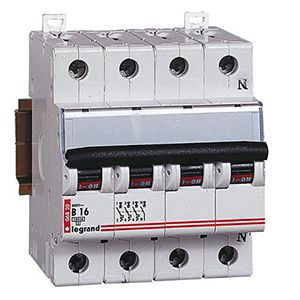
V three-phase network three or four-pole circuit breakers are used. In the TN-C system, all three phases L1, L2, L3 are connected to the upper terminals of the three-pole machine, and the neutral wire to the zero bus of the electrical panel.

Connection of a three-pole circuit breaker in a TN-S network system with neutral and protective earth
In the TN-S system with PEN protective grounding, three phases are connected to the upper terminals of the four-pole circuit breaker, and the blue neutral wire to the upper terminal of the fourth pole of the input circuit breaker marked N. The yellow-green protective PEN wire is connected to the electrical panel grounding bus.
Connecting wires to the machine
The installation of the circuit breaker is carried out on a DIN rail, the length of which is selected with the calculation of 17.5 millimeters per single-pole circuit breaker. When installing the cable, external insulation is removed from it by 10 - 15 cm to improve the flexibility of the wires and ease of installation.
The ends of the wires are protected by 7-10 mm and placed under the terminal contacts. It is not necessary to tighten the screw connections of the machine strongly in order to avoid skewing its mechanisms. When installing wires in the terminals of the machine, make sure that the insulation of the wires does not get under the contacts. In the best case, there will be an unreliable connection, and in the worst case, the phase on the contact will disappear.

Mounting connection rail for machines
For a multicore cable, for reliable contact, it is better to put copper lugs of the appropriate size. In the electrical panel, where several machines are installed in a row, it is convenient to install a copper connecting bus for the circuit breakers (comb). It is cut to the required length and installed in the correct sequence instead of wire jumpers.
Content:Automatic switches, called in everyday life automatic machines or switches, belong to the means of switching and are intended to supply electric current to any object. The main function of these devices is automatic shutdown supplying current in the event of an emergency and network faults. The machine protects the electrical circuit from short circuits, overloads and voltage drops in excess of the permissible value.
In the houses of the old construction, in the power supply system, the neutral wire was not only a worker, but also performed a protective function at the same time. In modern buildings, there is a clear separation according to the purpose of working and protective conductors. In this regard, the question often arises of how to connect a circuit breaker, since all European wiring products are equipped with terminals for connecting a grounding wire. In addition, the fixing of the machines themselves in the control cabinet can be done by mounting on a DIN rail or on a special mounting panel.
Device and principle of operation
Before connecting the machine, you need to understand the features of its design and the principle of operation. The circuit breaker consists of a housing, a switching device, a push-button or handle-like control mechanism, an arc chute and screw terminals located at the top and bottom.
For the manufacture of the housing and the control mechanism, a durable plastic is used that does not support combustion. The switching device consists of movable and fixed contacts. Each pole of the machine consists of a pair of these contacts and is equipped with its own arcing chamber.
The purpose of the arc chute is to extinguish the electric arc that occurs when the contacts are broken under the action of the load. The chamber itself is made in the form of a set of steel plates with a profile of a certain shape. They are isolated from each other and are located at the same distance relative to each other. It is to these plates that the arc is attracted, which here cools and fades away. Number of pairs of contacts in different models automatic machines range from 1 to 4. The devices have position indicators. Red indicates on and green indicates off. Thus, one can very quickly determine Current state circuit breaker.
All parts are hidden inside the case, only the upper and lower screw terminals, control handle and indicator are visible from the outside. There is a latch on the body that allows you to quickly install the machine on and just as easily dismantle it.

To turn off the machine, there is a special mechanism called a release. Each type of release has its own design. For example, in conventional machines, the function of the disconnecting device is performed by a coil with a winding and a core. Copper insulated wire is used for winding. The coil is connected to the electrical circuit in series with the contacts, since it is along it that the load current moves. If this current exceeds the set permissible value, then under the influence magnetic field coil core moves and exerts a mechanical effect on the disconnecting device. As a result, the contacts of the circuit breaker open.
The design of the thermal release has its own characteristics. It includes a special bimetallic plate. For its manufacture, two types of metals are used, dissimilar in their composition and with different coefficients of linear expansion. The plate is connected in series with the load. During the operation of the machine, it is heated by the current passing through it. In case of overload, the plate bends towards the metal with the lowest expansion coefficient. The trigger comes into action, turning off the machine. The more the current exceeds the rated value, the faster the thermal release will trip.
Installation of circuit breakers
The connection of the circuit breakers in the control cabinet is carried out in a specific sequence. A cable is started from above, connected to external source current, and through the outlets located at the bottom, the wiring is routed to its objects, in accordance with the electrical diagram.

At the beginning of installation, an introductory machine is connected. If there are several lines in the circuit, isolated from each other, they are separated from the input circuit breaker. Its power must be no less than the total power of the machines connected to separate lines. For this purpose, two- or four-pole devices of group D are selected, which are resistant to the inclusion of a power tool and other powerful equipment.
The most widespread are those suitable for any power supply schemes for apartments and private houses. The modular circuit breakers are mounted on a DIN rail and connected by conductors with a current carrying capacity exceeding the operating current of the circuit breaker. A more convenient connection of several machines in one row can be done using a special connecting bus. A piece of the required length is cut from it and fixed in the terminals. This connection is possible due to the distance between the bus contacts corresponding to the standard width of the modular machines. The switch is installed on a phase, and the neutral conductor is supplied from the input device directly to the devices.
- Single pole the switch is used when installing sockets and lighting systems.
- Bipolar the machine is suitable for high power appliances such as an electric stove or a boiler. In the event of overloads, it is guaranteed to break the circuit. The connection diagram of such switches is practically no different from single-pole models. For more efficient use, it is recommended to connect them to a separate line.
- Three-pole the circuit breaker should be installed only in cases where it is planned to use electrical appliances operating at a voltage of 380 V. In order to exclude, the load is connected according to the "delta" scheme. Such a connection does not require a neutral conductor, and the consumer is connected to its own switch.
- Four-pole a circuit breaker is most often used as an input. The main condition for connection is considered to be an even distribution of the load on all phases. When equipment is connected according to the "star" scheme or three separate single-phase wires, surplus current will go through the neutral conductor.
With an even distribution of all loads, the neutral conductor begins to perform a protective function in the event of unforeseen power imbalances. To ensure a normal connection, only high quality materials should be used. All connections must be securely fastened to the terminals. If several cables are connected at once, their contacts must be carefully cleaned and tinned.

The procedure for connecting can be seen on the example of a two-pole circuit breaker installed in a panel. First of all, the electricity is turned off in order to completely de-energize the network. The lack of electricity is checked using an indicator screwdriver or a multimeter. Then the machine must be installed on a DIN rail and latched with a latch. The absence of a mounting rail can create certain inconveniences. After that, the cores of the incoming and outgoing wires are stripped at a distance of 8-10 mm.
Input wires are connected to two clamps located on top. In the lower clamps, similar outgoing conductors are fixed, distributed to sockets, switches and electrical appliances. All wires are properly clamped in the terminals with screws. The connection points must be checked manually. To do this, the conductors must be gently wiggled from side to side. In the event of a poor-quality connection, the core will stagger in the terminal and may even jump out of it. In this case, the terminal screw must be tightened.
At the end of the installation, voltage is applied to the network and the functionality of the circuit breaker is checked.
How to choose the right machine
Is of great importance right choice circuit breaker. Each device has its own parameters, such as rated current, mains operating voltage, number of poles, maximum short-circuit current, time-current characteristic and other important values.

The response time of the device has a numerical designation indicating at what current the normal operation of the circuit breaker is maintained. At home electrical networks most often used machines with numbers 4500, 6000 and 10000 amperes. Everything specifications are indicated by the manufacturers directly on the device case. This also includes the connection diagram, as well as the symbol of the machine.
The main criteria for choosing a circuit breaker are considered to be the load power and the cross-section of the wires used. In addition, the overload current and the short-circuit breaking current are taken into account. As a rule, overloads in the network occur when devices and devices with a total power are turned on at the same time, causing excessive heating of conductors and contacts. Therefore, the tripping current of the machine installed in the circuit must be greater than or equal to the calculated one. Its value is defined as the sum of the capacities of all devices used, divided by 220.

The short-circuit breaking current also causes the circuit breaker to trip. It is selected by calculations for a specific circuit and depends on the loads used most often. In order to improve protection, they can be included in the electrical circuit.
Errors in the installation of the circuit breaker
When performing electrical work, sometimes serious mistakes are made, which can lead to negative consequences in the process of further operation.
- The power cable is connected from the bottom. Although it is not prohibited by the PUE, such a scheme will be inconvenient, since the installation and placement of machines in the panel is designed specifically for the upper connection.
- It is a common mistake to over-tighten the contacts with the retaining screws. This can lead not only to damage to the core, but also to deformation of the product body.
- Sometimes the wrong connection of the conductors is made to each other. It is necessary to pay close attention to the marking, connect the phase and neutral wires located at the top with the same wires located at the bottom.
- In some cases, one bipolar circuit breaker replaced by two single-pole. This categorically cannot be done, since they do not provide simultaneous phase and zero separation.
- Often, during the fixation of the core in contact, the insulation gets into the seat. This leads to a weakening of the contact, as a result of which the conductor overheats and other negative consequences. Therefore, it is imperative to protect the wire in accordance with the technical requirements. specific model machine. This operation should be carried out using a stripping tool.
The wrong choice of a circuit breaker, which subsequently is not able to withstand the planned loads, can play a negative role. Therefore, it is recommended to first perform all the necessary calculations, especially. It should be remembered that when calculating the value of the machine should be rounded down. For example, with a current load of 20 A, the circuit breaker should be selected for 16 A, which will significantly increase the life of the wiring.
It is difficult to imagine a switchboard without modern modular protection devices such as circuit breakers, residual current devices, differential circuit breakers and all kinds of protection relays. But these modular devices are not always connected correctly and reliably.
In view of the maintenance of electrical panels, I sometimes have to deal with errors in connecting the circuit breakers that are installed in them. It would seem, how can you incorrectly connect a conventional single-pole circuit breaker? I stripped the cable to a certain length, inserted it into the terminals, and tightened the screws securely.
But as strange as it sounds, most people have "gnarled" hands and the build quality of the shields leaves much to be desired. Although in fact we all make or have made mistakes in this or that industry, and as the well-known proverb says: "He who does nothing is not mistaken."
Greetings to all friends on the site "Electrician in the House". In this article, we will consider and analyze several options for the most common and gross mistakes.
Connecting vending machines in the dashboard - top or bottom entry?
The first thing I would like to start with is the correct connection of the machine in principle. As you know, the circuit breaker has two contacts for connecting movable and fixed. Which pins do you need to connect power to the top or bottom? To date, there have been a lot of controversies on this matter. On any electrotechnical forum, there are a lot of questions and opinions on this matter.
Let's turn to the regulatory documents for advice. What does the PUE say about this? In the 7th edition of the PUE, clause 3.1.6. said:
As you can see in the rules it says that supply wire when connecting machines in the shield should be connected, as a rule, to fixed contacts. This also applies to all ouzo, difavtomats and other protection devices. From this whole clipping, the expression "as a rule" is not clear. That is, it seems, as it should, but in some cases there may be an exception.
To understand where the movable and fixed contact is located, you need to imagine the internal structure of the circuit breaker. Let's look at the example of a single-pole machine where the fixed contact is located.

Before us is an automatic machine of the BA47-29 series from iek. From the photo it is clear that its fixed contact is the upper terminal, and the moving contact is the lower terminal. Considering electrical designations on the switch itself, it is also clear here that the fixed contact is on top.

Circuit breakers from other manufacturers have similar markings on the case. Take, for example, an automatic machine from Schneider Electric Easy9, it also has a fixed contact on top. For Schneider Electric RCDs, everything is similar on top there are fixed contacts, and on the bottom there are movable ones.

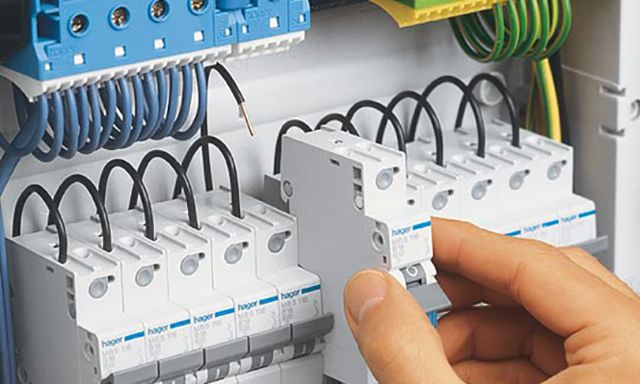
Another example, protective devices by Hager. On the case of the hager circuit breakers and RCDs, you can also see the designations, from which it is clear that fixed contacts are on top.


Let's see, from the technical point of view, is there a value, how to connect the machine from above or below.
The circuit breaker protects the line against overloads and short circuits. When overcurrents appear, the thermal and electromagnetic release located inside the housing react. From which side the power will be connected from the top or from the bottom to trip the releases, there is absolutely no difference. That is, we can say with confidence that the operation of the machine is not affected by which contact will be supplied with power.
In truth, I must say that manufacturers of modern "branded" modular devices, such as ABB, Hager and others, allow the power supply to be connected to the lower terminals. For this, the machines have special clamps designed for comb tires.
Why, in the PUE, it is advised to connect to fixed contacts (upper)? This rule is approved in order to general order... Any educated electrician knows that when performing work, it is necessary to remove voltage from the equipment on which he will be working. "Climbing" into the flap, a person intuitively assumes presence of a phase on top of the machines... Having disconnected AB in the shield, he knows that there is no voltage at the lower terminals and everything that leaves them.
Now let's imagine that an electrician, Uncle Vasya, performed for you, who connected a phase to the lower contacts AB. Some time has passed (week, month, year) and you need to replace one of the machines (or add a new one). Uncle Petya, an electrician, comes in, turns off the necessary machines and confidently climbs under tension with his bare hands.
In the recent Soviet past, all machines had a fixed contact at the top (for example, AP-50). Now, according to the design of modular AB, you cannot tell where is the movable, and where is the fixed contact. At AB, which we considered above, the fixed contact was located on top. And where are the guarantees that the Chinese machines have a fixed contact located on top.
For those who disagree with me, the question is about filling, why on electrical diagrams the power to the machines is connected to the fixed contacts.
If we take, for example, a conventional RB-type switch, which is installed at every industrial facility, then it will never be connected upside down. The connection of power to switching devices of this kind is supposed only to the top contacts. I turned off the switch and you know that the lower contacts are without voltage.
We connect the wires to the machine - a cable with a monolithic core
How do most users connect the machines in the dashboard? What mistakes can be made while doing this? Let's take a look at the most common errors here.
Error - 1. Contact with insulation.
Everybody knows that before it is necessary to remove the insulation from the connected wires. It would seem that there is nothing complicated here, I stripped the core to the required length, then we insert it into the clamping terminal of the machine and tighten it with a screw, thereby ensuring reliable contact.

But there are cases when people are at a loss why the machine burns out when everything is connected correctly. Or why the power in the apartment periodically disappears when the wiring and filling in the dashboard are completely new.

One of the reasons for the above hitting wire insulation under the contact clip of the circuit breaker. Such a danger in the form of poor contact carries a threat of melting of the insulation, not only of the wire, but also of the machine itself, which can lead to a fire.

To exclude this, you need to follow and check how the wire is tightened in the socket. Correct connection of the circuit breakers in the switchboard should exclude such errors.
Error - 2. You cannot connect several conductors of different cross-sections to one AB terminal.
If the need arose connect several machines standing in the same row from one source (wire) for this purpose, a comb bus is the best fit. But these tires are not always at hand. How to combine several group machines in this case? Any electrician, answering this question, will tell you to make homemade jumpers from the cable cores.


To make such a jumper, use pieces of wire of the same cross-section, or it is better not to break it at all along its entire length. How to do it? Without removing the insulation from the wire, form a jumper of the desired shape and size (according to the number of branches). Then we strip the insulation from the wire at the bend to the desired length, and we get an unbreakable jumper from a single piece of wire.

An example of connecting circuit breakers with jumpers from different cable cross-sections. The first automaton receives a "phase" with a 4 mm2 wire, and other automata already have jumpers with a 2.5 mm2 wire. The photo shows that jumper made of wires of different cross-sections... As a result, poor contact, temperature rise, insulation melting not only on the wires, but also on the machine itself.


For example, let's try to tighten two wires with a cross section of 2.5 mm2 and 1.5 mm2 in the terminal of the circuit breaker. No matter how hard I tried to ensure reliable contact in this case, nothing worked for me. A wire with a cross section of 1.5 mm2 dangled freely.


Another example in the photo is a difavtomat, into the terminal of which two wires of different cross-sections were stuck and tried to tighten the whole thing securely. As a result, the wire with a smaller section dangles and sparks.

Error - 3. Formation of the ends of the conductors of wires and cables.
This point most likely refers not to an error, but to a recommendation. To connect the veins of outgoing wires and cables to the machines, we remove the insulation from them by about 1 cm, insert the bare part into the contact and tighten it with a screw. According to statistics, 80% of electricians are connected this way.


The contact at the junction is reliable, but it can be further improved without wasting time and money. When connected to vending machines solid core cables Make a U-bend at the ends.


This formation of the ends will increase the contact area of the wire with the clamping surface, which means that the contact will be better. P.S. The inner walls of the contact pads AB have special notches. When the screw is tightened, these notches cut into the core, which increases the reliability of the contact.

Connecting stranded wires to the machine
For wiring switchboards, electricians often prefer a flexible wire with a multi-wire conductor of the PV-3 or PuGV type. It is easier and easier to work with it than with a monolithic vein. But there is one peculiarity here.
The main mistake that beginners make in this regard is connecting stranded wire to the machine without termination... If you compress the bare stranded wire as it is, then when tightening the veins are squeezed and break off, and this leads to a loss of section and deterioration of contact.


Experienced "experts" know that it is impossible to tighten the bare stranded wire in the terminal. And for the termination of stranded conductors, you need to use special tips NSHV or NSHVI.

In addition, if there is a need to connect two stranded wires to one terminal of the machine for this you need to use the double tip NShVI-2. With the help of NShVI-2 it is very convenient to form jumpers for connecting several group machines.
Soldering wires under the terminal of the machine - ERROR (error)
Separately, I would like to dwell on this method of terminating the wires in the shield as soldering. Human nature is so arranged that people try to save money on everything and do not always want to spend money on all kinds of tips, tools and all kinds of modern small things for installation.

For example, consider the case when Uncle Petya, an electrician from the housing office, conducts the wiring of the electrical panel with a stranded wire (or connects outgoing lines to the apartment). He does not have NSHVI tips. But there is always a good old soldering iron at hand. And the electrician Uncle Petya does not find any other way out how to irradiate the multi-wire conductor, stuffs the whole thing into the contact terminal of the machine and tightens it with a screw from the heart. Why is this dangerous?

When assembling the switchboards, DO NOT solder and tin the stranded conductor... The fact is that the tinned compound begins to "float" over time. And in order for such a contact to be reliable, it constantly needs to be checked and tightened. And as practice shows, this is always forgotten. The soldering begins to overheat, the solder melts, the junction is weakened even more and the contact begins to "burn out". In general, such a connection can cause a FIRE.


Therefore, if a stranded wire is used during installation, then NSHVI tips must be used to terminate it.
If you ask any person inexperienced in electrical engineering what is in an electrical panel, then an immediate answer will follow - automata. Although there may be, in addition to circuit breakers (this is the correct name for the machines), there may be differential circuit breakers, load switches, contactors, impulse relays and much more. The purpose of this article is to find out how to select the circuit breakers from the whole variety of modular devices, what they are intended for, how to choose them correctly, how to connect the machine in the panel and what to do when triggered.
At first glance, it may seem that an ordinary person who is completely unfamiliar with engineering science in general and electrical engineering in particular does not need to know anything about circuit breakers, because the wiring in an apartment or house was done by professionals. It is possible that this is so, but what will a person do if the tension suddenly disappears in the whole apartment or house or in some part of them. Of course, the person will open the flap, see what kind of "knocked out", and again move the lever to the "on" position.
It is in this action that the main mistake of "ordinary people" lies, because before turning on a triggered modular device, one must understand the reason for its operation. Therefore, do not be surprised when, after switching on again immediately or after a while, switching off again follows. Without eliminating the cause, you should never re-enable modular devices, including circuit breakers (hereinafter machines). This can lead to sad consequences both for the health and life of a person, and for property.

The fact is that on different devices protection has its own functions, therefore, the reasons for the operation of machines and (RCD) are completely different. And in most cases this does not apply to the quality of electrical wiring. Of course, an experienced electrician will always find the reason. But if incidents with electricity occur at night or on a weekend, then not every electrician will agree to promptly solve the problem that has arisen, and if he does, then the owners will have to pay well from their pockets for the urgency.
As the electricians themselves say, 50% of cases of triggering of protection devices are trivial and occur through the fault of the owners themselves and the wiring has nothing to do with it. That is why elementary basic knowledge about protection devices, their purpose and the rules of response when they are triggered will be very useful. The authors of the article will try to explain everything in understandable language, without going into the jungle of technical nuances that will be of interest only to specialists, but not to “ordinary people”.
What is a circuit breaker and what is it for?
A circuit breaker (machine) is a device that is designed to switch (in other words, turn on and off) an electrical circuit. That is, here we mean that you can manually turn on and off the electrical circuit using the lever.
However, the name itself - a circuit breaker, says that the machine should automatically turn off the load. When does this happen?
- When the circuit protected by the circuit breaker flows a current that exceeds the permissible one. And the greater the excess current, the faster the shutdown occurs.
- When very large currents appear in the protected circuit, which are unusual for the load - the so-called short-circuit currents. In these cases, the machine reacts very quickly - within a fraction of a second.
An overload can occur when one powerful load is simultaneously turned on in one circuit protected by the machine, for which neither the circuit breaker nor several powerful loads are designed. For example, in one outlet circuit of six outlets, an electric kettle, iron, electric fireplace, microwave oven, double boiler and hairdryer are turned on at the same time. Naturally, with such a load, the current will exceed its nominal values by much, the wires will be very hot from this, which can lead to melting of the insulation and, in the future, to a short circuit. The machine must not allow this and must disconnect the circuit even before the wires become very hot.

Short-circuit currents can occur when an insulation breakdown to the case occurs in any device or the phase and neutral conductors are closed. According to Ohm's Law, the lower the resistance, the greater the current. The higher the current, the more heat is generated, which leads to melting and ignition of the insulation. Short circuits are the most common cause of electrical wiring fires. That is why a very important function is assigned to the machine - to instantly react to short-circuit currents, that is, to those currents that are many times higher than the rated ones. The reaction time of the machine must be such that the wires do not have time to heat up to dangerous temperatures.
From all of the above, one important conclusion follows: the circuit breaker is designed to protect wires, cables and various included in the circuit electrical devices overload and short circuit. There is not a word about a person. Therefore, the main thing should be understood - the machine does not save a person from electric shock. The machine saves cables and wires.
Let's give an example. Suppose the lighting circuit in the apartment is protected by a 10 Ampere automatic machine and a person, changing a light bulb in a lamp, accidentally touched a live phase conductor, and touched the grounded refrigerator case with the other part of his body. An electric current begins to flow through the human body, which depends on the resistance - the more it is, the less the current. In the calculations, the resistance of the human body is taken to be 1 kΩ, which means the current will be I =U /R = 220/1000 = 0.22A = 220mA... For a lethal shock to a person, 80–100 mA is enough, and the machine has a rated current thousands of times higher. Therefore, we repeat - the machine does not save a person from the damaging factors of electric current. Of course, a triggered machine can save someone's life if it prevents the electrical wiring from igniting, but it does not save a person from direct exposure to electric current.
Briefly about the "inner world" of the machine
A circuit breaker is a complex electromechanical device. Some modern models of machines are equipped with electronic units that more accurately track the flowing currents, but in this article we will consider the device of the "classics". The sectional machine is shown in the following figure.

The terminals are located in the upper and lower parts of the machine, and it is always assumed that the entrance is at the top and the exit is at the bottom. The upper terminal is rigidly connected to a fixed contact, and the lower one is connected to a thermal release, which is a bimetallic plate that bends when heated. The end of the bimetallic plate is connected with a flexible conductor to one of the terminals of the solenoid of the electromagnetic release. Another output of the solenoid is connected with a movable contact by a flexible conductor.
The release mechanism is designed in such a way that the movable contact is spring-loaded and reliably fixed both in the on and off state. In addition, the springs allow switching very quickly, which avoids strong burning of the contacts during a spark or arc discharge, which can occur precisely at the moments of shutdown.
The release mechanism can be operated in three ways:
- Turning on the machine, that is, when the movable contact is pressed against the stationary one, only by hand, via the release control lever. You can also manually turn off the machine.
- In case of overloads in the circuit, the current, which exceeds the rated one, passes through the bimetallic plate of the thermal release, heats it too. Under the influence of temperature, the plate bends and presses the lever of the release mechanism, which turns off the machine. The higher the current overload, the faster the plate heats up and the faster the mechanism is triggered.
- If short-circuit currents appear in the circuit, then the current passing through the solenoid of the electromagnetic release induces a magnetic flux capable of drawing inside the spring-loaded solenoid core, which, in turn, acts on the movable contact and opens the circuit. In this case, the reaction time for good machines can be thousandths of a second.
At the moment of disconnection, a spark discharge may occur between the moving contact, which ionizes the atoms of the gases that make up the air. Ionized gas is good guide, therefore, an electric arc can break out, in which the temperature can reach several thousand degrees. Naturally, such a thermal effect will very quickly burn out the circuit breaker, unless special measures are taken.

The machines always have a special arc chute, which is a set of copper or copper-plated steel plates that are insulated from each other. When the arc ignites, it forms a powerful magnetic field, which induces an EMF in the plates, which also forms its own magnetic field of opposite polarity. These fields interact with each other, the arc is drawn into the plates of the arc chute. The plates "chop" the arc into pieces and cool it, as a result of which it quickly extinguishes. When the arc burns, a large amount of gases is formed, which freely leave the machine body through a special hole located below the arc chute. This process can take a fraction of a second, but even this time is enough for a spark discharge or arc to "scorch" the contacts a little.

Over time, with frequent switching on and off of the machines, the contacts burn out. There were times when the contact pads of circuit breakers were made of electrical silver, there are such devices now, but they are not used in household wiring. Therefore, it is not necessary to "click" the lever of the machine without special need, since at each action there at least a spark discharge jumps over, causing the erosion of the contacts. The machines are designed mainly to protect the cable or wire, and for switching there are special devices - load switches, called in Russian knife switches.
Find out its purpose, basic schemes, common mistakes, in a special article on our portal.
How to choose the right circuit breaker
Before installing a circuit breaker in an electrical panel, it must be correctly selected so that it matches both the cable and the nature of the load. Therefore, we will consider the main characteristics of modular machines, which are always indicated on their labeling. For a specialist, marking says a lot, but for an “ordinary person” it does not mean anything. Therefore, you need to learn how to read it, especially since there is nothing complicated about it.
Educational program on labeling machines, selection of the desired model
The figure shows typical markings for all circuit breakers. Let's consider all the points one by one and comment on which machines are needed for various purposes.

Trademark
The trade mark is always indicated in the upper part of the faceplate of the machine, which in other words means the manufacturer. For protection devices, this is of great importance, since it is better to choose an automatic machine from a well-known brand. These are: ABB, Legrand, Hager, Merlin Gerin, Schneider Electric, IEK, EKF. In the matter of choosing a specific model and series, it is better to consult a good (not ZhEKovskiy) electrician.
Rated voltage and frequency
If the machine has an inscription 220 / 400V 50 Hz, it means that this device can operate both in single-phase and three-phase AC circuits with a frequency of 50 Hz. Most machines used in household wiring have this opportunity.
Rated current
This is one of the main characteristics that indicates what maximum current in amperes can flow through the machine for a long time without triggering it. It is designated I n... If the current becomes more than the nominal by 13%, i.e. I =I n * 1.13, then the thermal release starts to work, but its response time will be more than an hour. Upon reaching I = 1.45 *I n the tripping time of the thermal release will already be less than an hour and the higher the current, the shorter the tripping time.
The rated current of the machine must always correspond to the cross-section of the cable or wire of the circuit it protects, but not the load power. The machine should not allow them to overheat when an electric current flows, however, in real life the opposite is often the case.
For example, a family has acquired a washing machine and, when plugged into an existing outlet, after a while in the driveway it knocks out an automatic machine, since the total load turns out to be higher than it can tolerate. An electrician who came from the housing office offers an “ingenious” solution to change the machine to another one with a higher rated current. For example, in the dashboard there was an automatic machine for 10 A and it is proposed to change it to 16 A, or even to 25 A, so that it was "more reliable". The machine is changing and, to the delight of the owners, it really stopped knocking it out when the washing machine was running. And it is made with an aluminum wire with a cross section of 1.5 mm 2, which is far from uncommon in houses built in the era of the USSR.
Naturally, at peak loads, the wire will overheat, its insulation will melt, but the machine will not react in any way, since its response threshold is much higher. Unfortunately, such situations are far from uncommon. And the owners will be very lucky if there is no fire, but a short circuit occurs, which will cause the machine to work.
It should be understood simple rules that will help you choose the right machine that is guaranteed to protect the wiring from overheating.
- or the wires must match the load.
- The circuit breaker rating should only correspond to the cross-section of the cable or wire, but not to the load.
The table below shows the correspondence of the cross-section of the copper cable or wire and the rated currents of the circuit breakers. In any case, it is necessary to be guided by just such a correspondence and nothing else. No exceptions and no arguments like "I've done this a hundred times."

It can be seen from the table that the machine does not allow using all the possibilities of a cable or wire for passing an electric current, but limits them. And this is done intentionally, the circuit breaker is a kind of "weak link" that will not allow the cable or wire to "strain" too much, which, from a safety point of view, is very useful.
Rated current circuit breakers are available in 1A, 2A, 3A, 6A, 10A, 16A, 20A, 25A, 32A, 40A, 50A, 63A.
Time-current characteristic
Before the value of the rated current in the marking of the machine, there is an alphabetic index that reflects the time-current characteristic (VTX). It is not known for what reason, but, from the point of view of the authors, not enough attention is paid to this. Let's figure out what this characteristic is.

The figure shows a graph of the dependence of the response time of the machine on the multiplicity of the flowing current to the nominal, that is k =I /I n... The graph is divided into three colored zones: green, blue and yellow, which corresponds to the time current characteristics of B, C and D. The following conclusions can be drawn from the graph:
- If k is greater than 3, but less than 5, the automaton belongs to category B.
- When k is greater than 5, but less than 10, the automaton belongs to category C.
- When k is greater than 10, but less than 20, the automaton belongs to category D.
What does this mean in human language? It can be seen from the graph that in any categories of machines, the greater the multiplicity of the flowing current in relation to the nominal, the faster the operation will occur. Circuit breakers with BTX category B react the fastest of all to overcurrent, followed by automatic circuit breakers of category C, followed by D. There are also machines with characteristics K and Z, but they are not used in apartment buildings.
It should be noted that the graph is given for certain external conditions, namely an ambient temperature of + 30 ° C. When the temperature rises, the automata will operate at slightly lower currents, and when the temperature is lowered, on the contrary, at higher currents. This difference is not so significant, but it still exists. A very great influence on the operation of circuit breakers is exerted by their "neighbors" on the electrical panel, which, heating up when an electric current flows through them, heats up the air inside the panel and the nearby equipment. That is why experienced electricians try to choose such models of electrical panels that have a lot of free space inside and, when assembling them, do not try to clog them with modular equipment "to the eyeballs."
The question is, why divide the circuit breakers into VTX categories. After all, you can simply make such an apparatus that will simply react by disconnecting to the excess of the flowing current over the nominal one. But not everything is so simple. Some types of electrical loads, when switched on, consume currents that are much higher than during operation. For example, the electric motors of a vacuum cleaner or refrigerator compressor may consume 3-8 times the rated current at the time of start-up. If the machines react to such an excess every time, then life will turn into a living hell - every time the refrigerator is turned on, the machine in the dashboard vibrates. That is why thermal releases are used in automatic machines, which have a certain inertia, which allows a short-term excess of current to be allowed, which does not lead to overheating of the wires. In any case, the thermal release is configured in such a way that it turns off the circuit before the cables and wires enter a dangerous mode for them.

In the wiring of apartments and private houses, circuit breakers from categories B and C are used. When choosing a specific model, the nature of the load should be taken into account. For active loads, that is, those that do not consume increased currents at startup, you should choose automatic machines with BTX type B. This applies to lighting and socket circuits. Reactive loads will already require type C VTX machines. These include refrigerators, air conditioners, washing machines and dishwashers, and home workshops where power tools are used.

Unfortunately, it is very difficult to find type B circuit breakers in electrical supply stores. This is due to the low demand for them. The lion's share of the machines sold is type C VTX. But the authors of the article strongly recommend not to spare money and use type B machines for active loads. Even if you have to order them and wait for a while. The fact is that by combining circuit breakers with characteristics B and C, it is possible to achieve selectivity in the operation of protection devices.
Let's give an example. Let's say an incandescent lamp burned out in one of the lamps, but at the same time the spiral closed. Surely everyone has come across such a situation when, when the light is turned on, the lamp flashes and immediately goes out with a characteristic click and at the same time knocks out the machine. It is good if the machine has worked, which protects only the lighting circuit of the room, but it can happen that it knocks out the machine located in the driveway. Moreover, it happens that the automatic machines in the apartment dashboard did not react, but the driveway did. If this happens, it means that selectivity is poorly organized in the organization of the wiring.
The main principle of selectivity is that the protection devices closest to the source of the problem must be triggered first. If for some reason they did not work, then other devices higher in the hierarchy should respond. In the described case, with a lamp, you can put an automatic machine with BTX type B on the lighting circuit, and install a category C automatic machine in the driveway. Then, when the lamp coil closes, first of all, a more "nimble" type B automatic machine will work, while the approach machine "dulls". In this case, its slower reaction is beneficial, as it will not lead to the shutdown of the entire apartment.
Rated breaking capacity
This characteristic can also be called the limiting switching capacity (PSC). The PKS shows at what maximum short-circuit current the machine will still be able to open the circuit at least one (and this will most likely be the last) time. The standard values of the PKS are 4.5 kA, 6 kA, 10 kA. For domestic use, 4.5 kA is quite enough, but if the substation is nearby, then it makes sense to use machines with 6kA PKS. Circuit breakers with PKS 10 kA are used only in industry.
Current limiting class
This characteristic has three values - 1,2 and 3, and if this marking is absent, then the machine belongs to the 1st class. It shows how quickly the machine will react to the appearance of short-circuit currents. If the thermal release, when an overload occurs, can "wait tactfully", then the electromagnetic release should act "decisively and boldly" when the TKZ appears. The class of current limiting precisely reflects the degree of "decisiveness" of the machine and the time of its reaction.

Class 1 opens the circuit in one half-cycle, which is about 10 ms in time, class 2 - in ½ half-cycle (5-6 ms), and class 3 in 1/3 half-cycle (3 ms). Naturally, the higher the class, the better, but also more expensive.
Number of poles
In modern apartment or house switchboards, modular circuit breakers with 1, 2, 3 or 4 poles are used. Single-pole and double-pole circuit breakers are designed to protect single-phase circuits, and three and four-pole - for three-phase. According to the number of poles, the circuit breakers occupy the number of places (modules) in electrical panel... One place is 17.5 mm.
Video: How to choose circuit breakers
As noted above, modern circuit breakers used in household wiring are modular equipment, which, along with other control, switching, metering and protection devices, have housings of standard sizes in length and height, and the width is always a multiple of one module (place) equal to 17 , 5 mm.
All modular equipment in electrical panels is mounted on a 35 mm DIN rail with a snap. To install, just snap the machine on the rail, and then, moving it to the left or right, set it to the desired position. And to remove it, you already need a flat-head screwdriver, which you need to pry and pull up the spring latch.

To install and connect the circuit breaker to the electrical panel, you will need a standard set of electrical tools:
- A set of screwdrivers, both straight and Phillips. You should pay attention to which screws, with which slot, are used in the terminals of the machine. There are two options: a Philips cruciform (in the figure numbered 2) or a Pozidriv cruciform (in the figure numbered 3). They are designated PH or PZ, respectively.

Each slot has its own tool: screwdriver or bit
- Pliers in various sizes.
- Nippers or cable cutters.
- Stripping tool - stripper.

- If stranded wires are used to connect, then you will need a tool for crimping the terminals - a crimper.

- Indicator screwdriver.
Let's describe the process of mounting and connecting the circuit breaker in the electrical panel.
| Image | Description of the process steps |
|---|---|
 | The electrical panel is completely de-energized, measures are taken to prevent unauthorized switching on of voltage. with an indicator screwdriver, the absence of voltage in the shield is checked. |
 | The automatic machine of the selected rating snaps into place on the DIN rail. |
 | If there are empty gaps to the left and right of the machine, then it is advisable to use special stops that prevent the equipment from moving left and right along the DIN rail. |
 | When connecting a single-pole circuit breaker, a phase from the input device or an RCD (individual or group) must be supplied to the upper terminal, and the phase of the protected circuit must be removed from the lower terminal. |
 | When connecting a two-pole circuit breaker, a phase should be applied to the upper left terminal, and zero to the right. The phase of the protected circuit should "leave" from the lower left, and zero from the right. |
 | When connecting a three-pole circuit breaker, the phases must be applied to the upper terminals in the order they follow from left to right A, B, C (L1, L2, L3). The phases of the protected circuit must respectively "leave" from the lower terminals in the same order. |
 | A four-pole machine is connected in the same way as a three-pole one, only a zero wire is added - the far right. |
 | In the electrical panel, suitable wires and wires of the protected electrical circuits are laid to the corresponding terminals of the circuit breakers. Incoming ones are routed to the upper terminals, and outgoing ones to the lower ones. The only way! When laying, use existing wire bundles. If necessary, the wires to be laid are tied to the bundles with plastic clamps. |
 | When laying wires, you should avoid sharp turns, which can provoke kinks. Also, do not pull the wire taut. |
 | When the wires are laid to the terminals of the machines corresponding to them, their required length is measured so that the wire freely enters the terminal. Excess ends are bit off. |
 | A stripper removes the insulation from the ends of the wires by 10 mm. In the absence of a stripper, this can be done with a construction knife, but at the same time you must try not to cut the insulation perpendicular to the wire - this can provoke further wire bunching. |
 | If stranded wires are used, then they must be terminated with NSHVI-type tips, which are crimped with a special tool - a crimper. |
 | If the circuit breaker is located next to the others in the electrical panel and one phase or phase is “heard” on all of them together with zero, then it is advisable to use special busbars-combs, which, like automatic machines, are one, two and three-pole. |
 | In the absence of combs, jumpers can be prepared from the PV3 assembly wire and NSHVI lugs (2), intended for crimping two wires. It is not allowed to place two separate wires under the terminal of the machine. |
 | After checking the conformity of the installation schematic diagram of the electrical panel, the wires are placed in the previously released terminals of the machine and are clamped with a screwdriver with a force of 0.8 N * m. Do not try to tighten "with all the stupidity", as this can lead to breakage of the machine case. |
 | Voltage is applied to the electrical panel, all protection devices are turned on, the presence of voltage at the input and output of the machine is checked with an indicator screwdriver or multimeter. |
 | The insides of the electrical panel are closed with a protective cover - a plastron. The circuit breaker is marked with its belonging to the protected circuit. Marking is also done on the plastron. |
Video: Circuit breakers - polarity and connection diagrams
What to do if the machine in the electrical panel is triggered?
If during the operation of the electrical wiring, a circuit breaker has tripped, then this can be for many reasons. Therefore, you should not rush to turn it back on immediately, but try to find out the source of the problem. In this case, one should be guided by the following:
- Any disconnection of the machine causes strong heating of its insides, especially the bimetallic plate of the thermal release and the solenoid. Before turning on the load, allow a few minutes to cool down.
- While the machine is cooling down, you need to walk around the apartment or house and inspect all the sockets, switches, lamps, powerful consumers of electricity. The smell of burning insulation, darkening from exposure to fire, hot plugs can tell a lot and indicate the source of the problem.
- If everything is in order with selectivity in the electrical panel and only one automatic device that protects a specific circuit has worked, then the task is simplified, since it is necessary to inspect the consumers of only this circuit. It is much worse when the input machine is triggered and the others “ignored” the problem. Then you will have to turn off all the lines protected by the circuit breakers, turn on the automatic input and sequentially turn on all the circuits, one at a time. After turning on any circuit, it is necessary to give a certain delay time and at the same time inspect all electrical appliances that are connected to the machine.
- If, when the automatic machines are sequentially turned on, one of them triggers or turns off the input machine, then the source of the problem has already been localized and the problem must be looked for in a specific circuit. It can be some kind of faulty consumer of electrical energy, a burned out lamp with a closed filament, melted insulation in some section of the wiring, and much more. To find out what is the matter, when the machine is off, it is necessary to turn off all consumers of electricity in this circuit, and then turn on the machine. If it works, then the problem is in and without the help of specialists. If not, then all consumers must be connected in series, which will help identify a faulty device.
- Turning off the machine in a separate line or input can provoke a very heavy load. For example, simultaneously included Washer, dishwasher, air conditioner and electric oven. The automatic input machine may not be designed for such a load, therefore it turns off the circuit. In this case, it is necessary to separate the operation of powerful electrical appliances in time.
- Hot summer weather combined with high loads can also trigger protection devices.
- And the last reason is a malfunction of the circuit breaker itself. It is possible that before that it had repeatedly tripped from increased currents, briefly endured short-circuit currents, and repeatedly extinguished the arc. All these influences, unfortunately, affect the life expectancy of the machine not for the better. With the plastron removed, you can inspect the insides of the shield. A faulty machine can be identified by a melted body, burnt terminals and other signs. A simple replacement of the circuit breaker can solve the problem.

Video: Circuit breaker - why does it work in the heat?
Video: Circuit breaker knocks out
Conclusion
- The circuit breaker is designed to protect the cable or wire, not people.
- The rated current of the machine must strictly correspond to the section of the protected cable or wire.
- In circuits with a resistive load, it is better to use machines with a time-current characteristic of category B, and with a reactive one having high starting currents- category C.
- A competent combination of circuit breakers with BTX B and C will ensure selectivity.
- When a circuit breaker is triggered, the source of the problem must first be identified. If you cannot do this yourself, then you should call a specialist.
Reliable and safe wiring for you!
Modern circuit breakers are very reliable in operation and have a number of advantages over other devices designed to protect electrical circuits.
They are devices with two contacts and a switch-off mechanism in a dielectric housing. It is an irreplaceable element of an electrical panel.
There are several parameters that you need to pay attention to when choosing:
Installation and connection in a switchboard
At the installation stage, it is assumed that the case is already assembled and installed, and is wound inside. This is followed by the stage of devices according to the previously developed connection diagram.
The connection of the differential circuit breakers in the switchboard is carried out according to the following scheme:

The following diagram shows how to connect the machines in the switchboard:

At this stage, it is necessary to install two buses - for grounding and a neutral wire, an input machine, and the required amount. All installation operations must be carried out only with the power supply turned off.
To start, it is necessary to install DIN rails inside the shield, they need to be screwed on with self-tapping screws using the perforation of the metal profile. DIN rails are metal strips designed for fixing devices and busbars.
The circuit breakers, RCDs and grounding bars are equipped with spring latches for mounting on a rail. After installation, they allow the devices to be moved freely along the rail.
On the rail, you need to install a zero (in the upper part of the shield) and a grounding bus (in the lower part). They are plastic-backed copper plates with conductor clamps. Only one conductor can be connected to each terminal.
After that, it is necessary to install an introductory switch that will power the entire electrical panel. His should be installed in the left upper corner corps, the lead-in cable should be located as close as possible. To connect a two-pole input circuit breaker in the switchboard, you need to connect, for a single-pole one - only a phase.
Then you need to start installing automatic devices for controlling the power supply of individual rooms and large consumers of electricity. Automatic machines are installed on a DIN rail, they are connected to the main wiring, brought into the shield.
Power is connected to the top terminal. The lower terminals are used to connect the phase conductors of the power supply of the groups according to the developed diagram. To connect the devices to each other, use comb-type busbars.
Everything neutral wires are connected to the zero bus, except for those that are connected using an RCD. has the same connection as the circuit breaker.
The ground is connected to the ground bus with a yellow-green wire. Metal case and the switchboard door must also be connected to it. After that, you can apply voltage to the electrical panel and check its performance with the help of tension.
Useful video on how to install an electrical panel in an apartment:
To avoid mistakes
Points to pay attention to when installing machines in an electrical panel with your own hands:

To independently select and install circuit breakers in an electrical panel, you need to perform a simple sequence of actions. The main thing in this process is this is the observance of security measures, as well as all the requirements of GOST and PUE.
How to carry out a competent installation of an electrical panel and automatic machines with your own hands, you can find out by watching this video: