An LED is a semiconductor device that resembles an ordinary diode in its structure. Therefore, you can check it like a normal diode - by switching it on in the forward direction, i.e. apply a positive voltage between the anode and cathode. Checking is not difficult if you have a regular tester on hand. Unlike conventional silicon diodes, the forward voltage of which is 0.6 ... 0.7 V, the LED has a much higher value of this parameter. Depending on the color and material, red ones have a voltage of 1.5 ... 2 V, green ones - 1.9 ... 4 V, white ones - about 3 ... 3.5 V. This information is indicated in the manufacturer's documentation.
Another feature of the light-emitting diode from the usual one is the low reverse voltage, which exceeds the direct one by only a few volts. This increases the risk of damage to the device if it is not turned on correctly or due to electrostatic discharge. How to make sure that the LED is working before mounting it on the board?
Almost any digital tester (or multimeter, as you like) allows you to quickly check the LED for performance.
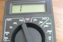
In the simplest case, to ring the LED, you need to turn on the multimeter in diode test mode, as shown in the figure below.

Next, we determine the polarity of the inclusion. For output LEDs, the cathode is usually shorter than the anode. If the conclusions are of the same length (someone “carefully” bitten), then we look at the clearance. The figure shows that inside the case itself there are two electrodes, usually the larger one is the cathode, but this is not always the case, so you should not take this as a rule.

It remains only to connect the tester to the outputs of the LED. Red probe to the anode, black - to the cathode (unless, of course, you have standard probe colors). Serviceability is determined by the glow.
In the same way, you can check a powerful LED. These are usually mounted on a metal substrate board (MCPCB). Polarity is usually labeled next to the pads. If not, then guess. The probability of damaging the LED with a tester is very small - not the same power.

It is even easier and more convenient to ring the output LEDs if the multimeter has a transistor test function. In this case, you just need to insert the leads into the appropriate connector. For NPN section: anode in hole C (collector), cathode in hole E (emitter). For the PNP section, it is exactly the opposite. A visual check is shown in the figure below.

When it comes to powerful lighting LEDs operating at currents of the order of hundreds and thousands of mA, there is such a defect: when “ringing”, the LED is highlighted and recognized as suitable, and when it is turned on for operating current, it shines like “full heat”. This is due to a crystal defect, and if it is difficult to replace defective LEDs in a finished product (for example, a spotlight), then you need to check them in advance.
A more thorough check, in addition to a multimeter, will also require a current source. A laboratory source is ideal, but an adapter for charging mobile phones or other devices will also work. The main thing is that it has current stabilization.
The sequence is:
- we switch the multimeter to the limit of "10 A" (do not forget to rearrange the probe to the appropriate socket) and connect it to the circuit in series between the LED and the power source;
- turn on the power, measure the current, turn off the power;
- we turn on the multimeter in parallel with the LED, setting the measurement limit to “20 V” (again, without forgetting to rearrange the probe, otherwise we will arrange a short circuit), we connect the source directly to the LED, observing the polarity;
- turn on the power, measure the voltage drop across the LED, turn off the power;
- we check the serviceability by matching the current and voltage according to the current-voltage characteristic curve given by the manufacturer in the data sheet.
Checking the infrared receiver

As you know, the IR receiver is a specialized microcircuit. This complicates its verification. But, despite this, you can check the IR receiver. This will require some equipment. Namely:
power unit. It is desirable that the power supply be stabilized with an output voltage of 5 volts. You can successfully use a homemade power supply with adjustable output voltage.
Digital multimeter. Any digital multimeter with the ability to measure DC voltage will do.
Any serviceable remote control(DU).
Before you start checking the IR module, you need to determine the pinout of its outputs. If this is not done, then you can "burn" the IR module. If an unknown IR receiver fell into your hands, then you should not rush to connect it. First you need to carefully examine it from all sides and find its markings. Further on the marking we find the datasheet for this model of the IR receiver on the website alldatasheet.com or through a google search. Read about how to do this. As a rule, in the datasheet there is a picture indicating the pinout. It's easy to figure it out.
For the TSOP31236 receiver model, on which the tests will be carried out, the pinout looks like this.

Conclusion number 1 is the conclusion of the common wire ( GND). The negative wire of the power supply is connected to this output. Pin number 2 is the positive pin ( Vs). The positive wire of the power supply is connected to it. Pin number 3 is the receiver signal output ( OUT).
If the necessary equipment is prepared, and the pinout of the IR receiver is determined, then we assemble the test circuit. It is better to assemble the test circuit on a solderless breadboard. This will take a couple of minutes. If there is no solderless breadboard, then you will have to solder the test circuit by surface mounting.
So, we assemble or solder the test circuit. The positive output from the power supply (+5 V) is connected to the positive output of the IR module (Vs), the negative - to the negative output of the IR receiver (GND). And the third output of the IR receiver (OUT) is connected to the positive ( red) to the multimeter probe. Negative ( black) we connect the multimeter probe to the common wire (GND) of the test circuit. We switch the multimeter to the DC voltage measurement mode ( DC) to the limit of 20 V.
Verification method.
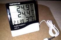
Those who have already learned what an IR receiver is know that while the IR receiver does not receive radiation from the remote control, there is a voltage at its output that is almost equal to its supply voltage. That is 5 volts. It will not change until “packs” of infrared pulses from the remote control begin to fall on the sensitive photodiode of the receiver. The photo shows that the output (OUT) of the IR receiver is 5.03 volts.

The essence of the test is to check the change in voltage at the output of the IR module when infrared radiation from any remote control hits it.
As soon as packets of infrared pulses from the remote control begin to fall on the photodiode of the IR receiver, the voltage at its output will drop. In theory, it should drop to almost zero, but since the multimeter does not have time to respond to a change in voltage, it will show a voltage drop of several hundred millivolts. Recall that the remote control signal is in the form of bursts of pulses. That is why an ordinary multimeter does not have time to reflect such rapid changes in the voltage at the output of the module on the display.
We press any button on the remote control and do not let go. In this case, it will be seen how the voltage value drops from 5.03 volts to 4.57 on the multimeter display. The output voltage has decreased by 460 millivolts (mV).

If you release the button on the remote control, then the voltage value will return to 5 volts on the display.
As you can see, the infrared signal receiver correctly responds to the signal from the remote control. Means IR module OK. Similarly, you can check other infrared signal receivers in a modular design.
I think it is clear that if the IR receiver does not respond to signals from the remote control and the voltage at its output does not change even by a millivolt, then with a high degree of probability it can be argued that the IR receiver is faulty. In practice, an IR receiver HS0038 was tested, taken from a color TV, which burned out during a thunderstorm. So, when checking the IR receiver, it turned out that there was no voltage at its output even in the “standby” mode, and the current consumption was 0. The IR module turned out to be burned out (most likely due to an excess supply voltage of more than 6 volts).
Among the infrared receivers of the TSOP series and similar ones, there are so-called low-voltage specimens. In their marking, they have the number 3. The representative of such a low-voltage IR module is TSOP 3 1236. This IR receiver already works with a supply voltage of 3 volts.
If a low-voltage instance of an IR receiver is being tested (for example, such as TSOP31236), then the IR module can be supplied with a supply voltage of both 3 volts and 5 volts. The method for testing such an IR receiver is similar to that described.
When checking infrared signal receivers, it is worth remembering that any of them has a filter in its composition. This filter is tuned to a certain frequency, usually in the range of 30-40 kilohertz. But in practice, an IR module with a filter tuning frequency of both 56 and 455 kilohertz can also fall into the hands (you never know). So, such a receiver can and will receive an infrared signal from an ordinary remote control, but there will be no signal at the output. Why? Because the remote control will emit a signal modulated with a frequency of, for example, 36 kilohertz, and the receiver is set to receive a signal modulated with a frequency of 455 kilohertz. It is clear that in this case the signal simply will not pass through the filter.
For widely used IR receivers of the TSOP series and analogues, the filter tuning frequency is usually 36; 36.7 and 38 kilohertz. They receive a signal well from almost any remote control taken from consumer electronics. And even if the filter frequency does not exactly match the modulation frequency of the signal from the remote control, the signal will be received. Sometimes all you need to do is move the remote closer to the IR receiver.
Today, LED lamps have become very popular. They have the same base as ordinary incandescent lamps. The bottom line is that they consume significantly less energy, and also last much longer.
It is not difficult to buy LED light bulbs at the best price in Ukraine. After all, today there are a large number of specialized online stores. Prices and assortment will pleasantly surprise you.
Due to the fact that the lamp has an ordinary base, it is not difficult to check it. All that is required for this is to screw it into the cartridge. Below are other tests that will identify a poor-quality product:
- the base must be tightly fixed;
- the lamp should not flicker;
- during five minutes of operation, the lamp should not warm up.
Checking the fixing of the base can be quite simple. You just need to try to loosen it with two fingers. If this succeeds, it is better to refuse to purchase such a lighting fixture.
Today, almost everyone has a smartphone with a camera. The flicker check is as follows - you need to turn on the lamp in the network and shoot it on video. No need to shoot for a long time. A few minutes will be more than enough.
If you notice the flickering of the lamp while watching the video, it is better to refuse the purchase. LEDs should not flicker if they are fully technically sound.
Quality lighting fixtures can be found at http://light-electro.com/catalog/svetodiodnye/.

However, cheapness is achieved at the expense of quality deterioration - this is the only way. For this reason, price can be a relative measure of quality. However, relying on it completely does not make sense.
As a rule, the resource of the LED lamp should be indicated on the box itself. In most cases, it is 30,000 - 35,000 hours. It should be noted that this is an average value.
The resource can reach up to 50,000 hours. However, if the package says 5,000 or 10,000 hours, there is no point in buying such a lamp. It probably won't last longer than a month.
The video will talk in detail about what pitfalls you can expect in choosing a lighting fixture with LEDs:
Light-emitting diodes (LED) are often used in modern lighting technology. As you know, they are much more reliable than ordinary light bulbs, but still they can sometimes fail. In order to test the LED for operability, several methods are used. Let's take a closer look at each of them.
Verification methods
The LED has its own electrical parameters, this is the maximum operating current, as well as a direct voltage drop. Manufacturers indicate the value of the first parameter for each product individually, and the second is 1.8 - 2.2 volts for orange, yellow and red diodes. For white, green and blue 3 - 3.6 volts. Checking these parameter values with a multimeter is not difficult.
Another way to check the led diode for operability is to supply power to it from several parallel-connected AA batteries or one crown battery. Based on this method, you can independently make a universal tester for LEDs, using improvised elements. A detailed process of determining the health is shown in the video.
You can determine a faulty LED using old mobile phone chargers as a current source for testing. To do this, you need to cut off the connection plug to the phone, and strip the wires. The red wire is a plus, it needs to be pressed to the anode, the black one is a minus, it is connected to the cathode. If the voltage of the power supply is sufficient, then it should light up.
To test some diodes, the voltage from charging the phone may not be enough, then you can try to check with a more powerful device, such as charging from a flashlight. In this way, it is quite possible to check the diodes in the led lamp for operability. How to do it, watch the video.
Checking with a multimeter
A multimeter is a versatile measuring instrument. With it, you can measure the main parameters of almost any electronic product and not only. To check the LED, you will need a multimeter in which there is a "continuity" mode, or it is also called the diode test mode. The designation of the diode test mode on the multimeter is shown in the image below.
In order to check the LED with a multimeter, you need to set the device switch to the position corresponding to the "dialing" mode and connect its contacts to the tester's probes.

During the connection process, the polarity of the diode must be taken into account. The anode should be connected to the red probe, and the cathode to the black one. In cases where there is no information which electrode is the anode and which is the cathode, you can mix up the polarity - it's okay, nothing will happen to the LED. If connected incorrectly, the multimeter will not change its original readings. When connected correctly, the LED should light up.

There is one caveat, the “ringing” current is low enough for the LED to work normally, and it is worth dimming the lighting in order to see how it glows. If it is not possible to do this, you can focus on the readings of the measuring device. As a rule, if the LED is working, then the multimeter will show a value other than one.
The second option is to check the LED with a tester, this is to use the PNP block. This connector, designed to test diodes, allows you to turn on the LED at a power sufficient to visually determine its performance. The anode is connected to the connector marked with the letter E (emitter), and the cathode of the diode is connected to the connector of the block, marked with the letter C (collector).

The LED should be on when the multimeter is turned on, regardless of the mode selected by the regulator.
This method allows you to check even sufficiently powerful LEDs. Its inconvenience is that the diodes must be soldered. To check with a multimeter without soldering, it is necessary to make adapters for probes.
There is an option to check the LED by measuring resistance, but for this you need to know its characteristics, which is not practical enough.
How to check without soldering
In order to connect the multimeter probes to the connectors in the PNP block, you need to solder small fragments of an ordinary paper clip on them. Between the wires on which the paper clips are soldered, for insulation, you can install a small textolite gasket and wrap it with electrical tape. Thus, we get a simple and reliable adapter for connecting probes.

Next, you need to connect the probes to the legs of the LED without soldering it from the product circuit. Instead of a tester, you can use one crown battery, or several AA batteries, to test the led diode. The connection is carried out in the same way, just instead of an adapter, you can use small crocodile clips to connect the probes to the battery outputs.

Let's look at a specific example of how to check led without soldering it from the circuit.
How to check the LEDs in a flashlight
To check, you need to disassemble the flashlight and remove the board on which they are installed. The check is carried out using a tester with probes connected to the PNP connector. You can not solder the LEDs, but connect the probe contacts to them directly on the board, while remembering to observe the polarity.
You can also determine a broken LED by measuring the resistance in the connection diagram. For example, if the LEDs in a flashlight are connected in parallel, by measuring the resistance and getting a result close to zero on any of them, you can be sure that at least one of them is definitely faulty. After that, you can start checking each of the LEDs using the methods described above.
Testing LEDs is not a difficult process, and anyone with a few working batteries and a couple of wires can test and determine if a fixture is faulty.
LEDs have been used in electrical engineering for a long time. But if earlier they were used exclusively as a variety of indicators, today the scope of these elements has expanded significantly.
With the help of infrared diodes, signals are transmitted from remote controls and various sensors, they are also used in surveillance cameras, instrumentation and other devices.
Another variety - super-bright elements, having finally learned to glow for real, quite confidently crowd out traditional light sources - incandescent lamps and even more advanced and economical fluorescent lamps.
It is unlikely that at least someone these days has not heard of, for example), and almost everyone has a flashlight with this type of light bulbs. One way or another, LEDs are being used more and more, and therefore we are increasingly faced with the need (when trying to find out the cause of a breakdown of a device) to check their performance.
superbright
Checking yellow, blue and white LEDs used as light sources and called super-bright ones is not particularly difficult. To do this, it is enough to connect the terminals of the element to a power source with a voltage of 3 to 4.2 V (no more!).
As such a source, it is most convenient to use a pair of 1.5-volt batteries connected in series. But the fact of the matter is that they are not always available at hand.
Is it possible to check using a conventional multimeter, which every radio amateur has, especially since modern versions of this device have a special mode for testing diodes?
It turns out that there is such a possibility. Although the mentioned mode, due to insufficient power supply, will not help in this case. Instead, we will use transistor parameter measurement mode, which is also provided in every modern model of a digital multimeter.
Digital multimeter
To study transistors, the tester is equipped with a special connector to which the element's leads are connected. It is marked with the letters PHP. The cathode of the ultra-bright LED (this is the shortest lead) must be connected instead of the collector (position "C" on the connector), and the anode - instead of the emitter (position "E"). If the element is good, it will start to glow, and the position of the measurement mode switch in this case does not matter.
In most cases, the lighting element is a part and plugging it directly into the PHP connector without soldering will not work. It is not possible to check it with probes, since they cannot be connected to the connector.
You can solve the problem by making a simple design consisting of an adapter and probes connected to it from an old or broken multimeter.

Standard multimeter leads
How to make probes with an adapter to a PHP connector
We need very little:
- two unnecessary probes (plugs must be cut off);
- a small fragment of double-sided textolite;
- a pair of metal clips;
- (required for ease of use, but the device will work without it).
A paper clip should be soldered to the textolite plate on each side, after bending their ends 180 degrees. You will get something like an electric plug.


Textolite plates
The thickness of the textolite fragment should be such that the distance between the pins of the "plug" corresponds to the distance between the inputs "C" and "E" on the PHP connector. That's all, the adapter is ready. It remains to solder to it (again on both sides) the wires from the probes.
It is better to place the textolite between the paper clips asymmetrically. Thanks to this, it will be easier to understand which side should include the adapter in the transistor connector of the multimeter, so as not to reverse the polarity.
The design can be supplemented with an SMD type LED, which will be assigned the function of an indicator.
How to make a dipstick with your own hands
If you don’t have standard probes that could be sacrificed, homemade ones can be used instead. To make them you will need:
- a pair of needles;
- tinned wire with a diameter of 0.2 mm (removed from the stranded wire).
The wire should be wound around the needle so that its turns fit snugly together, and then soldered. It is very convenient to use nickel-plated needles for this purpose., then soldering is done as easily and quickly as possible. Often such a probe provides better contact than a standard one.
infrared
As we purchase consumer electronic devices, each of us gradually becomes the owner of a whole battery of remote controls. As long as the equipment obediently responds to your commands, there is nothing to worry about.
But it is quite likely that  when desperate attempts to change the channel or turn down the brightness of the chandelier do not lead to any result. In such cases, first check the status of the infrared LED, through which the remote control transmits your requirements to the main device.
There are several ways to check the IR LED in the remote control or other device. Let's start with the simplest:
Direct the radiation of the diode into the lens of a digital camera. Not only a camera is suitable, but also a phone, a laptop, a DVR, a web camera, etc. IR radiation is absolutely invisible to the human eye, but electronic "eyes" register it very well. If the LED performs its functions properly, purple flashes will be observed on the matrix.
In the absence of a gadget that can shoot, a suspicious LED can be dismantled, replacing it with a super-bright or SMD-type LED. Just make sure that the operating voltage of both elements is the same.
If the test LED emits visible light when you press the buttons on the remote control (most likely it will be dim), then the IR LED has already served its purpose.
A more complicated way, but neither a camera nor soldering is required. You can use an infrared photodiode. When infrared radiation hits the sensor of this element, a potential difference is formed at its terminals.
To test any IR LED, its radiation must be directed to the sensitive zone of the photodiode, previously connected to the open input of the oscilloscope.
If at the same time pulse curves appear on the screen of the device, the tested LED is in working condition. If you observe complete calm, then it's time to buy a new IR LED.
Diagnostics of the LED in the flashlight
Or other types of a fairly reliable device, but it is not immune from breakdowns. If even after installing new batteries, the glow remains weak or completely absent, it is necessary to check the performance of the LEDs and their drivers.
Before diagnosing a flashlight, it is useful to test the batteries (even if they have just been unpacked) on some known good device. To some, this advice will seem banal, but quite often, as practice has shown, defective batteries become the cause of “showdowns” with consumer electronics, which the home craftsman guesses last.
Flashlight check is performed in the following sequence:
- We unscrew the cover or conical part in the front of the case.
- Remove the LED module.
- There are two contact pads on the LED board, to which the red and black wires are connected. The red wire corresponds to the positive polarity (marking "+" on the board), and the black wire - negative (marking "-"). In accordance with the polarity, a voltage of 3 - 4 V should be applied to the contacts for a short time (no more than 4.2 V!). If the brightness of the LED does not change, then it needs to be replaced. Otherwise (the LED lights up properly), the driver must be replaced.
- Replacing an LED is only possible if its board is attached to the LED module capsule with screws. If the board is planted on hot-melt adhesive, the replacement will be impractical, in this case the entire module is changed.

This is what the LED module looks like in the Magicshine flashlight
After unscrewing the board, unsolder the LED, and then install a new one.
In flashlights, LEDs are mounted on aluminum radiators. For effective heat dissipation, a fresh layer of a special heat-conducting paste, also called thermal paste, should be applied to the heatsink before installing a new LED on the heatsink. The old dried layer, even if it is quite thick, cannot be reused and must be removed.
Visually checking a separate LED and the simplicity of the tester device is demonstrated in the following video from the largest supplier of electrical equipment in Russia.
Often, when an electronic device breaks down, we without hesitation carry the victim for repair, where we are presented with a solid bill. Meanwhile, the cause of the accident may be just a failure of the LED, which can be easily replaced on your own.
Thus, the ability to check the performance of these elements, which are used quite widely today, will save money and reduce repair time to a minimum.