Digital LED sign that brightens up the beach after dark
For one of the houses on the beach, a fashionable sign was purchased. The word "BEACH" (Beach) was written on it, and the letters were arranged vertically. Initially, the sign came with blue LEDs that illuminated each letter. The problem was that the LEDs emitted a very narrow beam of light, and blinded people who were on the other side of the room. In addition, there was no way to change the color of the LEDs, which could significantly diversify the sign. Therefore, it was decided to update the signboard using multi-colored LEDs.
After removing the cardboard backing, the original LEDs were removed by tapping lightly with a hammer. As a replacement, it was decided to use individually addressable, WS2811 RGB pixel LEDs. This made it possible to widely diversify the color scheme and add animation. The LEDs came coated with a waterproof polymer material. I had to heat them with a heat gun to a brittle state, after which this coating was removed with pliers and a knife. Then the LEDs were installed in their old places in the sign and fixed with hot glue.
The next step was the selection remote control control, fortunately it was found at a relatively low cost, complete with a microcontroller, http://aliexpress.com/e/ieeeMZr. The LED controller was removed from its plastic case and soldered to the string of LEDs. After that, it was hot glued to cardboard and placed in a sign, along with the original battery box. The original sign, powered by two AA batteries.
In the video below, the results of the sign upgrade are well demonstrated:
Now, a little more about the modernization of the sign:
Removing old LEDs
From the cardboard backing, the original insides have been removed. The LEDs popped out easily with a light tap with a hammer. In fact, they can be reused for future projects where this type of LED would be more appropriate.
Installing new WS2811 LEDs
As mentioned above, the new LEDs that arrived had to be prepared first by removing the protective polymer layer from them. A total of 25 LEDs were used in the project.
The controller boards coming out of the LEDs were bent at 90 degrees to the surface of the sign and then installed in place of the old LEDs with hot glue.
Remote controller remote control and controller 21 key RF led pixel WS2811//WS2812B
Usually, for such projects, Arduino microcontrollers or similar were previously used. But in this project, the low cost of the radio remote control bundled with the microcontroller left no chance for these microcontrollers. In addition, the use of a radio remote control does not require drilling holes in the body of the sign to install an IR sensor.
The microcontroller is programmed for 63 various modes jobs that can be changed using the remote control. It also supports the ability to change the brightness of the LEDs, though only for primary colors. This would be an obvious direction for improving the circuit if it were self-assembled. First, the controller board is removed from the plastic case. Since the microcontroller connector is designed to connect a different type of strip, it was cut off and replaced with a suitable one. If you wish, you can look for controllers with a suitable connector, but in this case this is not relevant.
The microcontroller with a new connector was glued to a cardboard pad (made of several layers of cardboard) and placed in the sign case, next to the original battery compartment, and fixed with metal brackets.
The project is ready!
Source: xodustech
By
PIXELFLEX™ LED Walls Create New Opportunities for Retail
Combining style and science, the global footwear brand Vionic Shoes has seen continued growth driven by a recent move to a new showroom located at 1370 New York Ave in New York City. In this new environment, where reps and merchants are interested in acquiring the latest innovative shoe designs for their outlets, a new beach shoe brand, Vionic Beach, was also introduced. To make sure the latest designs don't get lost in the showroom, retailers and showcase designer David Warwick have developed a unique and exciting way to highlight the latest in footwear with PixelFLEX™'s FLEXLite II 3.9mm LED Video Wall.
PixelFLEX™ FLEXLite LEDs are an economical and dynamic solution that caters to both indoor and outdoor needs, ideal for any retail environment. With a bright, dense display and high refresh rate, the FLEXLite LED sections and factory calibration ensure perfect color and brightness.
“Once we started working on the showroom layout, we had a center area that really stood out as the best place to set up a Vionic Beach display. It was a beautiful, empty wall measuring 3 x 2.5 meters. It was from there that we began to explore what technology we could use to create a "wow" factor for buyers and draw their attention to a new brand. Since this was to serve as a prototype for what we could do in other outlets, we didn't want to use conventional stands and static displays. It wouldn't have brought us the success we had planned, so we decided to go with an LED video solution,” says David Warwick.
Now for customers, suppliers, business partners and members of the media who want to take a look at Vionic Shoes' latest innovations, Vionic Beach's new video booth design works great for the company by taking visitors on a fast journey to the relaxing memory of loose sand between their fingers.
“The goal of the project was for the LED video to immerse the viewer in the Vionic Beach brand, so the content is a relaxing beach environment with palm trees swaying in the breeze and the ocean rolling in after it,” David Warwick concluded.
Product information for FLEXLite II 3.9mm LED by PixelFLEX™ is available at: pixelflexled
By
150 MEDIA STREAM LED Screen by LEVIATHAN
Located in an exclusive building, a new commercial tower in Chicago, the stunning 3,000+ square foot LED video canvas serves as a dynamic digital sculpture for office building tenants and visitors.
To avoid over-repetition of works of art, Leviathan has developed an intelligent content library that will continuously evolve over time and provide the curators of the 150 Media Stream installation with maximum flexibility. Using generative algorithms to improve originality and relevance, the system is programmed to take into account seasonal, monthly, weekly, daily, and even real-time events.
These tools, combined with a robust planning system and live images from other customers, ensure that the view of the plant remains visually enticing at all times of the day. This groundbreaking improvement attracts new tenants and even allows art to be shared with the public.
Source: website
By
Our company LED-RUSSIA took an active part in the preparation for the new season. 26 to 27 July were truly outstanding in the life of the stadium. 8.192*4.608 anti-vandal and windproof screen, and the whole system was specially designed for this stadium. The screen with a pixel pitch of 16 mm used the best diodes currently supplied by our partners. Thanks to this, we have achieved excellent picture quality, which you can only find there.
Especially for this occasion, we have prepared video materials
“We were happy to bring to life all our ideas, which were still at the development stage, this project reunited many innovations in the field of LED products. Thanks to the well-coordinated work of our specialists, we have manufactured and released a unique screen in the shortest possible time. On behalf of the whole company and on my own behalf, I would like to express my gratitude to all the workers on this project and the customers themselves," says Anatoly Siyantsev, head of the LED-Russia division.
“LED-Russia has done a tremendous amount of work: production, quality control of all products, repeated checks of all equipment, delivery, installation work - we are the only ones who carefully monitor the entire process, from production to testing of all equipment already on site . We are certainly proud of our work, and we are ready to cooperate again” - Semyon Dzyunik, Leading Specialist of this project.
Go to LED-RUSSIA website
By
Reinterpreting the Montreux Jazz Festival in terms of an aesthetic of light and glamour, the Swiss firm bureau A has designed a series of illuminated boardwalks along the water's edge. They are located on the eastern shore of Lake Geneva in Switzerland. This famous festival has been the site of many legendary jazz and rock concerts. Led signs of the project look great against the backdrop of the Alps. LED letters glow brightly in different colors and are able to change it at random.
Sourced from designboom
A friend asked me not so long ago to help him with the purchase of components for a running line, with which he wanted to decorate his shop a little.
We had only seen them with others before, so we began to figure out how to organize it all.
We chose what we wanted, I ordered, received it and decided to try it at home first.
There will be inspection, disassembly and picking with all sorts of pieces of iron, however, as always :)
Initially, we considered a monochrome panel (usually a red glow) or a full-color one, I said that if you do it, then of course it will be a full-color one, there will be more variety of design options.
We ordered everything in one store, but first the power supply, and then everything else. BP was ordered earlier because there was a promotion, as it turned out later, fake, the price is the same.
And so, I ended up with a small box with a power supply and a large box with everything else. 
There were no questions about the packaging of particularly important components, everything was very neatly and tightly packed, for which the seller is a plus. There was a parcel "Mist Express". 
The LED panels were packed in one large sheet of foamed polyethylene, they did not rub against each other, as they were essentially wrapped through a layer. 
And now the whole set.
1. Power supply. , price $18.05, free shipping.
2. Onbon bx-5ql control board, price $16.88 ($22.73 with shipping).
3. Three P4 LED panels, price $13.98 ($57.17 for 3pcs with shipping)
In total, the whole set came out for about $ 98, later I will return to the issue of price. 
In addition to the items mentioned above, the list included:
1. A CD with software, I was too lazy to get a DVD drive to see what's there, since it's easier all this on the Internet on the official Russian-language site.
2. Fasteners. I didn't think so, it looks like a lot. Usually, they also order a frame to which everything is attached, but it is not very cheap and they decided to do it on their own.
3. A set of cables. Two power, each designed to connect two panels. And four signal, one long (to the controller) and three intermodular. Since there are three panels, the third short cable is superfluous, but it can be used if the controller is near the panel.
4. The controller contacts have been additionally protected, which is good. 
A small handkerchief controls the whole process. At the time of the order, I knew almost nothing about it, well, maybe except that you need to look at the supported resolution and the ability to work in full color mode.
By the way, as far as I understand, there are three types - monochrome (one color), two colors and full color (256 colors). As you already understood, we chose the latter option.
The board is called Onbon bx-5ql. 
There are empty spaces on the board, as well as contacts for connecting external devices.
There were no particular complaints about the build quality.
Judging by the documentation, the board can work with two sets of hub75 or four hub08.
The maximum supported resolution is 256x65 pixels. 
To connect external devices, the board contains:
1.
A very harsh terminal block for connecting power, voltage - 5 Volts. It is “harsh” because the consumption of the board is very small, and the terminal block is large :)
Nearby there are places for installing humidity and temperature sensor connectors, one of them will come in handy later.
2.
To the left of the power contacts there is a place for some kind of universal contact group, the reset contacts are also displayed there. There is a "test" button next to it. Above you can see a self-resetting fuse for a current of 0.75 Amperes (this is about the size of the terminal block). Although this is done here simply for ease of connection, I inserted the wire, screwed it, securely.
3.
USB connector for "filling" the control program, next to it there is a place for a photodetector (there is a version with remote control).
4.
Also on the board there is a place for a connector for connecting to local network and, accordingly, the controller, but we bought a "light" version of the controller. 
But the panel connectors created the biggest problem for me. On the one hand, everything is simple, four connectors of the same color, two of the other. But for some reason there is no information on them anywhere, I understood that they are intended for connecting panels different types, but the connectors do not have a key, and the panel does not indicate its type.
As a result, I just rang the contacts with the tester (the pinout is noticeably different) and connected it. 
1. ARM STM32F207 is used as the "brain".
2. In addition, the board has a 1GB (128MB) flash memory for storing the control program.
3. The panel outputs are connected via HC245 bus transceivers.
4. Also on the board there is a battery to power the clock, a small watch quartz is visible nearby. 
And here is the panel itself. The resolution of the panel is 64x32, when choosing a control board, remember that the total resolution of the panels should not exceed the capabilities of the controller.
In our case, it was 192x32 (three panels), the controller can be 256x64 or 512x32, so it turned out even with a large margin.
Panel dimensions 256x128mm. 
The panels are quite thin, about the thickness of a matchbox. 
Each panel consists of a large number of LEDs (in this case, 2048 pieces), partially covered by a frame. 
In the middle there is a division into two parts, each has a size of 32x32. The plastic frame is pressed with nine small self-tapping screws. And they are barely noticeable, my wife saw right away, but I overlooked :)
The photo shows the joint of the halves of the panel, the fit is very good. 
The case has bevels that allow you to fit the panels to each other "to zero", and if desired, even with a negative angle, i.e. “wrap” something round with them, although the radius will be large. 
Let's see how it all works.
The LED panel is a plastic frame construction, printed circuit board with components and a mesh front frame that holds the whole structure together.
There are M3 mounting holes on the case frame, which allow you to mount this entire structure on a special metal frame. 
The board has a black matte color, it looks like a fairly neat assembly. 

A little about the components.
As far as I understand, the board has DP5020 LED drivers, ICN2012 controllers and the same HC245 bus drivers as on the control board.
Power is supplied through a four-pin connector, and for data there are two identical-looking connectors, a data input and an output.
The controller is connected to the “input” connector, the next panel to the “output” connector, and so on. 
While I was preparing the materials, I completely forgot about the power supply. In general, I originally wanted to make a separate review about it, but I decided to just tell and show it here.
The power supply was originally packed in a cardboard box, wrapped in bubble wrap inside, although its case is so durable that I think it would not have suffered anyway.
All photos of the PSU were taken after preliminary tests of the panels and a small thermal run, later I will explain why I wrote this.
The PSU has a declared power of 200 watts and an output voltage of 5 volts. 
The power supply is the so-called "low profile". The photo shows a comparison with a more familiar PSU with a power of 240 watts and a voltage of 12 volts.
The dimensions of the power supply are 190x84x31mm. 
The terminals for connecting power and load are located on different sides of the case and both do not have protective covers, which is bad, or rather, unsafe. 
There is nothing else to look at from the outside, we climb inside.
The lid is held on by as many as six screws and two stickers, one with the release date, the other "OTK". 
The input filter is present in almost full volume, capacitors, inductor, fuse and thermistor.
Input bridge diodes - 1N5408, as for me, it will be “not enough”, but in fact it is quite normal.
The capacitance of the input capacitor is unknown, by measuring it I found out that it is 130 uF, for a power of 200 watts this is not enough. 
A high-voltage transistor 09N90 was used in the power supply, I did not look for a datasheet, I will assume that 9 Amperes 900 Volts.
Reading other reviews, I often come across phrases - why disassemble something that works fine.
So it is so, I also tried this PSU, gave it a load when I tested working with panels. But when I opened it, I really went nuts (I wrote it rougher, but I can’t). The power transistor is NOT SCREWED. The photo shows that there is no nut, it was not me who unscrewed it, it was not there. On the reverse side of the screw there is a sticker “OTK test passed”, irony of fate or cruel sarcasm.
Tin as it is. But as the inspection showed, that's not all, but more on the rest later.
Already in the process of writing a review, I remembered what the build quality of this PSU reminded me of.
A circuit nestled between the case and the transformer feedback and an output voltage regulator.
Sometimes I think that Chinese engineers still read my reviews. Out of fright, they put a bunch of class Y1 capacitors and where necessary and where you can not put, just for reinsurance. 
The transformer is very flat, wound not with a litz wire, which is customary in such cases, but with a bus.
The output inductor is wound in four wires, at a load of about 40% it starts to buzz noticeably.
Four 3300uF 10V capacitors are installed at the output, the total measured capacitance is about 14000uF. 
I did not remove the board from the case, but I was somewhat surprised by the presence of four diode assemblies at the output, and two types, even the cases are different. Maybe I'll take apart the PSU and then make a separate review of it, but I haven't thought about it yet.
And this is a continuation of the "gesture". One pair of diodes has an aluminum spacer between the diodes and the body, so this spacer is crooked. But other than that, the diodes were not actually pressed, I unscrewed the screws even without effort, the screws were only baited and simply held the clamping bar.
The high-voltage transistor was also not only not screwed, but had no thermal contact with the case at all, the gap was probably a millimeter.
Here's what to do here? 
Okay, enough about the sad, let's move on to the panels and their connection.
Since the dimensions of the panels are quite large, I will show the example of two pieces.
The panels are connected with a complete cable, the connectors have a key, so it is very difficult to confuse.
We also connect the power supply with a complete cable, one cable for two panels.
We connect a cable from the controller to the Data_IN connector, in this case a long cable is connected.
The following panels are connected in the same way. 
We connect the power wires to the PSU, initially there are quite convenient “fork” terminals on the cables. But the wires for connecting the power supply of the controller were not given, I had to do with improvised means. 
Almost at the beginning of the review, I wrote that I could not find instructions for connecting the board on the Internet. There are a lot of videos and photos on how to set up the software, calibrate the panels, but not a single photo with a cable connected (of this controller model).
Having called the connectors, I found out that it is necessary to connect as shown in the photo. Presumably one-color panels are connected to black connectors. 
The cable is a little long, most likely designed for a thick chassis, the excess can be folded as shown in the photo. 
First inclusion. Initially, a program was written that displays a running line from the characters AAAAABBWBB, you can also enter the test mode, where the modes Red, Green, Blue, White, Off and different stripes are sorted.
And the first trials different programs, as well as displaying the image. Sorry for the “shaking camera”, I shot on a camera without an image stabilizer, and held it with one hand, the other tried to connect a USB flash drive.
when a flash drive is connected, the program is automatically “uploaded” to the controller, and the current time at the time the program was created is also stored there, i.e. If you connect the USB flash drive again in an hour, then the clock will lag behind by the same time. In theory, this function is disabled in the program, I have not yet figured it out.
The image did not come out very well due to the backlight, in reality the colors are more juicy.
There were also minor annoyances.
On one of the panels caught "floating" dead pixel of red color. 
Moreover, if you touch it with your finger, it turns on, it can also turn on on its own initiative, in general, it lives its own life. I specially marked it with a marker, although even then it turned out to be difficult to find it in the off state. 
I shot a video for the seller, how it looks in reality.
But the video was not needed, the seller himself, without disputes, offered to return most of the cost of the panel or send a new one at the next purchase. But since I did not plan to buy panels yet, I chose a refund. So there are no questions to the seller about "technical support".
Actually, there was a reason to look at the LEDs more closely.
We unscrew nine screws (the central one has a shorter length) and remove the frame. The frame sits quite tightly and the screws are there rather “just in case”. 
There are many, many :) 
We find a broken LED, with the idea of simply soldering it. 
But alas, it is soldered normally, the dialing showed that it goes out even if you connect the power directly to its terminals.
By the way, in the photo is just a general output and a red output. 
We continue to play with the panel, a really good toy :)
First I tried different modes work. 
And then I remembered that we were looking for a controller with thermometer support. We find the Dallas 18B20 sensor in the stash and simply insert it into the holes for the connector, we didn’t want to solder the connector yet, especially since it might not work. 
But everything went fine, the controller "saw" the sensor immediately. 
As I wrote, the panel supports the output of images, in theory even GIF, but I did not find a suitable one for testing. But without problems, you can display static images.
Here the image quality is closer to the real one than in the video. 
I tried to display my cat as well :) Since the resolution of the matrix is not very large, you should carefully select the resolution of the picture so that it is clear what is on it.
In the photo there are two versions of the picture with a cat, I think the difference is visible.
Here I noticed a glitch, if you display the temperature readings, or rather, simply enable this function in the software, then interference periodically appears on the image, and they are even with the missing sensor, but a little more often. On the last photo they are visible, bright horizontal stripes. They are also not always there, I have not yet understood the logic of the appearance. 
During the selection process, and even after the tests, a friend asked me how much such a panel consumes energy, since where the panel will stand, electricity is very expensive.
That's why I did some consumption tests. Initially, I told a friend that consumption is highly dependent on what we display on the screen, but it's one thing to say, and another thing to measure.
In the photo, the current consumption on the bus is 5 Volts, measured using current clamps, since the voltage is low and connecting a conventional multimeter would distort the readings. All measurements are in 100% brightness mode, three panels are connected.
1. Red
2. Green
3. Blue
4. White 
1. Off
2. Some graphics from native test
3. Text
4. Text + image approximately 40% of the screen. 
At the same time, the network consumes
1. Red
2. Green
3. Blue
4. White
5. Off
6. Some graphics from native test 
have been checked and temperature conditions after an hour run.
On the right, the image and text were alternately displayed, on the left, the clock was constantly displayed, in the middle, the temperature.
The temperature of the panels themselves is not very high, but where the picture was displayed, the installation locations of the drivers that feed the LEDs are clearly visible.
At the end of the photo of the power supply, it was taken even before I took it apart and found out that the power transistor was not screwed on. 
As I wrote at the very beginning, they gave a CD with software in the kit, but it was easier for me to download it from the official site.
The software is called LedshowTW 2016 and I will show it a little now. Initially, I downloaded the version with GIF support, but it is somehow “semi-Chinese”, and then it was skewed in general and I had to install another one, everything is fine with it and it is more correctly Russified.
And so, download the software, install, run. 
But before starting work, you must at least configure the type of controller and the mode of operation.
Initially, the software is set to monochrome mode and another controller. 
We select the mode - full color, the name of our controller will also be there bx-5ql.
As a result, it has such a settings window. In the process, it will swear that there is no connection with the controller, you can ignore it, this is normal. 
After that, the start window will change, colored stripes “border” will appear around the perimeter of the virtual screen. Then I turned off these stripes, since they take two pixels out of 32.
Use the zoom in/out buttons to increase or decrease the size of the preview.
Initially, it worked exactly as a preview, you could watch it without writing software to the controller, but then this function stopped working :( 
Then we press - picture / text, a new item will be formed in the program.
When choosing - "Subtitles" there will be a running line, "Text" - a static line with switching effects. 
If you click on the folder icon, you will be prompted to open the image. 
When you select an image, a preview will appear, where there will be a rectangle that displays our resolution and, accordingly, what will be on the screen.
By moving this rectangle over the image, we select what will be displayed on the panel. 
By selecting the clock or thermometer at the top, you can display the time or temperature value, respectively. Moreover, the temperature can be displayed in different colors depending on the threshold value. 
The software has quite a lot of different settings, I won’t paint everything much, since it’s difficult for the review, it’s easier to find a training video on the Internet.
Miscellaneous settings


After completing the preparation of the project, you need to transfer all this to the controller. Since our controller can only work with USB, we accordingly prepare a USB flash drive with the program.
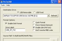
This is done very simply, USB flash A card formatted in FAT16 or FAT32 is inserted into any USB port on the computer. In the software, select USB, and then - Save.
Recorded on a flash drive boot file with the controller program.
As soon as the software gives a notification (at the bottom of the window) that the recording is successful, disconnect the USB flash drive from the computer and connect it to the controller, then everything is automatic, this was seen in the previous videos. 
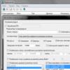
There is a brightness adjustment in the software settings, but apart from the usual one (16 levels), I found a less understandable automatic one.
In any case, after adjustment, it is necessary to click not “installation”, but “close” since the installation implies a direct connection of the software to the controller and there will be an error message.
By the way, I noticed that when the brightness decreases, the speed of the scrolling line also decreases, by about 1.5-2 times, this should be taken into account. 
I wrote that I need a flash drive in FAT32 to work, and it so happened by chance that I had as many as five such flash drives at home :) 
If you think that this is so unusual, then you are mistaken. I have five fake flash drives ranging from 11MB to 46MB. No one knew where to put them, but here they came in handy. 
The fact is that usually the volume of the program is not very large, while most of it is occupied by images. For example, the program shown in the video takes only 160kB :)
The slowdown of the image is not the fault of the panel, but the shortcomings of shooting with the camera.
I could end here, but I would like to talk a little about how I made a big clock and ended up not finishing it :(
I had a problem, I wanted to make a big clock, in the end I even soldered two large boards, the clock is big :) 
A little more under the spoiler
At first I tried to make a clock with NTP synchronization and all sorts of goodies (NTP clock).
They were assembled according to a ready-made scheme and special drivers for LEDs were needed there. I did not find such as it should be, but for others it is necessary to rewrite the program.
As a result, one fully assembled board hung, even varnished. 

The second copy turned out to be more successful, though simpler. Gathered according to the scheme - Clock on Atmega.
Both clocks use a real-time clock powered by an ionistor (it can be seen on the board). 

Accordingly, there is a power supply on each board, i.e. boards are complete solutions and you just need to connect indicators to them. 
The indicators were recruited from 5mm bright matte LEDs. I chose suitable LEDs for a long time, I did not want to blind my eyes.
And the whole process began in the manufacture of the case: ( 
Now that's probably all.
pros
Kit works
More than enough functionality
You can assemble your "creep line" without using a soldering iron
Low cost solution
Normal seller.
Minuses
The power supply has an extremely poor build quality
Interference when activating the thermometer (I hope to solve)
One dead red pixel :(
My opinion. First, let me tell you about the price. When I counted the number of LEDs on one panel and then figured out how much they cost, I would be extremely surprised how the manufacturer managed to cram it into $ 20:
1. 2048 RGB LEDs
2. Plastic chassis
3. PCB
4. Chipset
5. Set of wires
6. Fasteners
7. Delivery
And at the same time earn something from it. I can’t imagine how this can be done here, I think that this is generally unrealistic. Panels are produced in huge quantities, but still ...
Well, in general, I liked the system, it’s simple, beautiful, it works. You can assemble even an unprepared person, the software is in Russian, what else do you need :)
+144
+253
A friend asked me not so long ago to help him with the purchase of components for a running line, with which he wanted to decorate his shop a little.
We had only seen them with others before, so we began to figure out how to organize it all.
We chose what we wanted, I ordered, received it and decided to try it at home first.
There will be inspection and disassembly and picking with all sorts of pieces of iron, however, as always :)
Initially, we considered a monochrome panel (usually a red glow) or a full-color one, I said that if you do it, then of course it will be a full-color one, there will be more variety of design options.
We ordered everything in one store, but first the power supply, and then everything else. BP was ordered earlier because there was a promotion, as it turned out later, fake, the price is the same.
And so, I ended up with a small box with a power supply and a large box with everything else.
There were no questions about the packaging of particularly important components, everything was very neatly and tightly packed, for which the seller is a plus. There was a parcel "Mist Express". 
The LED panels were packed in one large sheet of foamed polyethylene, they did not rub against each other, as they were essentially wrapped through a layer. 
And now the whole set.
1. Power supply. , price $18.05, free shipping.
2. Onbon bx-5ql control board, price $16.88 ($22.73 with shipping).
3. Three P4 LED panels, price $13.98 ($57.17 for 3pcs with shipping)
In total, the whole set came out for about $ 98, later I will return to the issue of price. 
In addition to the items mentioned above, the list included:
1. A CD with software, I was too lazy to get a DVD drive to see what's there, since it's easier all this on the Internet on the official Russian-language site.
2. Fasteners. I didn't think so, it looks like a lot. Usually, they also order a frame to which everything is attached, but it is not very cheap and they decided to do it on their own.
3. A set of cables. Two power, each designed to connect two panels. And four signal, one long (to the controller) and three intermodular. Since there are three panels, the third short cable is superfluous, but it can be used if the controller is near the panel.
4. The controller contacts have been additionally protected, which is good. 
A small handkerchief controls the whole process. At the time of the order, I knew almost nothing about it, well, maybe except that you need to look at the supported resolution and the ability to work in full color mode.
By the way, as far as I understand, there are three types - monochrome (one color), two colors and full color (256 colors). As you already understood, we chose the latter option.
The board is called Onbon bx-5ql. 
There are empty spaces on the board, as well as contacts for connecting external devices.
There were no particular complaints about the build quality.
Judging by the documentation, the board can work with two sets of hub75 or four hub08.
The maximum supported resolution is 256x65 pixels. 
To connect external devices, the board contains:
1.
A very harsh terminal block for connecting power, voltage - 5 Volts. It is “harsh” because the consumption of the board is very small, and the terminal block is large :)
Nearby there are places for installing humidity and temperature sensor connectors, one of them will come in handy later.
2.
To the left of the power contacts there is a place for some kind of universal contact group, the reset contacts are also displayed there. There is a "test" button next to it. Above you can see a self-resetting fuse for a current of 0.75 Amperes (this is about the size of the terminal block). Although this is done here simply for ease of connection, I inserted the wire, screwed it, securely.
3.
USB connector for "filling" the control program, next to it there is a place for a photodetector (there is a version with remote control).
4.
Also on the board there is a place for a connector for connecting to a local network and, accordingly, a controller, but we bought a "light" version of the controller. 
But the panel connectors created the biggest problem for me. On the one hand, everything is simple, four connectors of the same color, two of the other. But for some reason there is no information on them anywhere, I understood that they are intended for connecting panels of different types, but the connectors do not have a key, and its type is not indicated on the panel.
As a result, I just rang the contacts with the tester (the pinout is noticeably different) and connected it. 
1. ARM STM32F207 is used as the "brain".
2. In addition, the board has a 1GB (128MB) flash memory for storing the control program.
3. The panel outputs are connected via HC245 bus transceivers.
4. Also on the board there is a battery to power the clock, a small watch quartz is visible nearby. 
And here is the panel itself. The resolution of the panel is 64x32, when choosing a control board, remember that the total resolution of the panels should not exceed the capabilities of the controller.
In our case, it was 192x32 (three panels), the controller can be 256x64 or 512x32, so it turned out even with a large margin.
Panel dimensions 256x128mm. 
The panels are quite thin, about the thickness of a matchbox. 
Each panel consists of a large number of LEDs (in this case, 2048 pieces), partially covered by a frame. 
In the middle there is a division into two parts, each has a size of 32x32. The plastic frame is pressed with nine small self-tapping screws. And they are barely noticeable, my wife saw right away, but I overlooked :)
The photo shows the joint of the halves of the panel, the fit is very good. 
The case has bevels that allow you to fit the panels to each other "to zero", and if desired, even with a negative angle, i.e. “wrap” something round with them, although the radius will be large. 
Let's see how it all works.
The LED panel is a construction of a plastic frame, a circuit board with components, and a mesh-like front frame that holds the entire assembly together.
There are M3 mounting holes on the case frame, which allow you to mount this entire structure on a special metal frame. 
The board has a black matte color, it looks like a fairly neat assembly. 

A little about the components.
As far as I understand, the board has DP5020 LED drivers, ICN2012 controllers and the same HC245 bus drivers as on the control board.
Power is supplied through a four-pin connector, and for data there are two identical-looking connectors, a data input and an output.
The controller is connected to the “input” connector, the next panel to the “output” connector, and so on. 
While I was preparing the materials, I completely forgot about the power supply. In general, I originally wanted to make a separate review about it, but I decided to just tell and show it here.
The power supply was originally packed in a cardboard box, wrapped in bubble wrap inside, although its case is so durable that I think it would not have suffered anyway.
All photos of the PSU were taken after preliminary tests of the panels and a small thermal run, later I will explain why I wrote this.
The PSU has a declared power of 200 watts and an output voltage of 5 volts. 
The power supply is the so-called "low profile". The photo shows a comparison with a more familiar PSU with a power of 240 watts and a voltage of 12 volts.
The dimensions of the power supply are 190x84x31mm. 
The terminals for connecting power and load are located on different sides of the case and both do not have protective covers, which is bad, or rather, unsafe. 
There is nothing else to look at from the outside, we climb inside.
The lid is held on by as many as six screws and two stickers, one with the release date, the other "OTK". 
The input filter is present in almost full volume, capacitors, inductor, fuse and thermistor.
Input bridge diodes - 1N5408, as for me, it will be “not enough”, but in fact it is quite normal.
The capacitance of the input capacitor is unknown, by measuring it I found out that it is 130 uF, for a power of 200 watts this is not enough. 
A high-voltage transistor 09N90 was used in the power supply, I did not look for a datasheet, I will assume that 9 Amperes 900 Volts.
Reading other reviews, I often come across phrases - why disassemble something that works fine.
So it is so, I also tried this PSU, gave it a load when I tested working with panels. But when I opened it, I really went nuts (I wrote it rougher, but I can’t). The power transistor is NOT SCREWED. The photo shows that there is no nut, it was not me who unscrewed it, it was not there. On the reverse side of the screw there is a sticker “OTK test passed”, irony of fate or cruel sarcasm.
Tin as it is. But as the inspection showed, that's not all, but more on the rest later.
Already in the process of writing a review, I remembered what the build quality of this PSU reminded me of.
A feedback circuit and an output voltage regulator nestled between the case and the transformer.
Sometimes I think that Chinese engineers still read my reviews. Out of fright, they put a bunch of class Y1 capacitors and where necessary and where you can not put, just for reinsurance. 
The transformer is very flat, wound not with a litz wire, which is customary in such cases, but with a bus.
The output inductor is wound in four wires, at a load of about 40% it starts to buzz noticeably.
Four 3300uF 10V capacitors are installed at the output, the total measured capacitance is about 14000uF. 
I did not remove the board from the case, but I was somewhat surprised by the presence of four diode assemblies at the output, and two types, even the cases are different. Maybe I'll take apart the PSU and then make a separate review of it, but I haven't thought about it yet.
And this is a continuation of the "gesture". One pair of diodes has an aluminum spacer between the diodes and the body, so this spacer is crooked. But other than that, the diodes were not actually pressed, I unscrewed the screws even without effort, the screws were only baited and simply held the clamping bar.
The high-voltage transistor was also not only not screwed, but had no thermal contact with the case at all, the gap was probably a millimeter.
Here's what to do here? 
Okay, enough about the sad, let's move on to the panels and their connection.
Since the dimensions of the panels are quite large, I will show the example of two pieces.
The panels are connected with a complete cable, the connectors have a key, so it is very difficult to confuse.
We also connect the power supply with a complete cable, one cable for two panels.
We connect a cable from the controller to the Data_IN connector, in this case a long cable is connected.
The following panels are connected in the same way. 
We connect the power wires to the PSU, initially there are quite convenient “fork” terminals on the cables. But the wires for connecting the power supply of the controller were not given, I had to do with improvised means. 
Almost at the beginning of the review, I wrote that I could not find instructions for connecting the board on the Internet. There are a lot of videos and photos on how to set up the software, calibrate the panels, but not a single photo with a cable connected (of this controller model).
Having called the connectors, I found out that it is necessary to connect as shown in the photo. Presumably one-color panels are connected to black connectors. 
The cable is a little long, most likely designed for a thick chassis, the excess can be folded as shown in the photo. 
First inclusion. Initially, a program was written that displays a running line from the characters AAAAABBWBB, you can also enter the test mode, where the modes Red, Green, Blue, White, Off and different stripes are sorted.
And the first samples of different programs, as well as image output. Sorry for the “shaking camera”, I shot on a camera without an image stabilizer, and held it with one hand, the other tried to connect a USB flash drive.
when a flash drive is connected, the program is automatically “uploaded” to the controller, and the current time at the time the program was created is also stored there, i.e. If you connect the USB flash drive again in an hour, then the clock will lag behind by the same time. In theory, this function is disabled in the program, I have not yet figured it out.
The image did not come out very well due to the backlight, in reality the colors are more juicy.
There were also minor annoyances.
On one of the panels there was a “floating” dead red pixel. 
Moreover, if you touch it with your finger, it turns on, it can also turn on on its own initiative, in general, it lives its own life. I specially marked it with a marker, although even then it turned out to be difficult to find it in the off state. 
I shot a video for the seller, how it looks in reality.
But the video was not needed, the seller himself, without disputes, offered to return most of the cost of the panel or send a new one at the next purchase. But since I did not plan to buy panels yet, I chose a refund. So there are no questions to the seller about "technical support".
Actually, there was a reason to look at the LEDs more closely.
We unscrew nine screws (the central one has a shorter length) and remove the frame. The frame sits quite tightly and the screws are there rather “just in case”. 
There are many, many :) 
We find a broken LED, with the idea of simply soldering it. 
But alas, it is soldered normally, the dialing showed that it goes out even if you connect the power directly to its terminals.
By the way, in the photo is just a general output and a red output. 
We continue to play with the panel, a really good toy :)
At first I tried different modes of operation. 
And then I remembered that we were looking for a controller with thermometer support. We find the Dallas 18B20 sensor in the stash and simply insert it into the holes for the connector, we didn’t want to solder the connector yet, especially since it might not work. 
But everything went fine, the controller "saw" the sensor immediately. 
As I wrote, the panel supports the output of images, in theory even GIF, but I did not find a suitable one for testing. But without problems, you can display static images.
Here the image quality is closer to the real one than in the video. 
I tried to display my cat as well :) Since the resolution of the matrix is not very large, you should carefully select the resolution of the picture so that it is clear what is on it.
In the photo there are two versions of the picture with a cat, I think the difference is visible.
Here I noticed a glitch, if you display the temperature readings, or rather, simply enable this function in the software, then interference periodically appears on the image, and they are even with the missing sensor, but a little more often. In the last photo you can see them, bright horizontal stripes. They are also not always there, I have not yet understood the logic of the appearance. 
During the selection process, and even after the tests, a friend asked me how much such a panel consumes energy, since where the panel will stand, electricity is very expensive.
That's why I did some consumption tests. Initially, I told a friend that consumption is highly dependent on what we display on the screen, but it's one thing to say, and another thing to measure.
In the photo, the current consumption on the bus is 5 Volts, measured using current clamps, since the voltage is low and connecting a conventional multimeter would distort the readings. All measurements are in 100% brightness mode, three panels are connected.
1. Red
2. Green
3. Blue
4. White 
1. Off
2. Some graphics from native test
3. Text
4. Text + image approximately 40% of the screen. 
At the same time, the network consumes
1. Red
2. Green
3. Blue
4. White
5. Off
6. Some graphics from native test 
The temperature conditions after an hour run were also checked.
On the right, the image and text were alternately displayed, on the left, the clock was constantly displayed, in the middle, the temperature.
The temperature of the panels themselves is not very high, but where the picture was displayed, the installation locations of the drivers that feed the LEDs are clearly visible.
At the end of the photo of the power supply, it was taken even before I took it apart and found out that the power transistor was not screwed on. 
As I wrote at the very beginning, they gave a CD with software in the kit, but it was easier for me to download it from the official site.
The software is called LedshowTW 2016 and I will show it a little now. Initially, I downloaded the version with GIF support, but it is somehow “semi-Chinese”, and then it was skewed in general and I had to install another one, everything is fine with it and it is more correctly Russified.
And so, download the software, install, run. 
But before starting work, you must at least configure the type of controller and the mode of operation.
Initially, the software is set to monochrome mode and another controller. 
We select the mode - full color, the name of our controller will also be there bx-5ql.
As a result, it has such a settings window. In the process, it will swear that there is no connection with the controller, you can ignore it, this is normal. 
After that, the start window will change, colored stripes “border” will appear around the perimeter of the virtual screen. Then I turned off these stripes, since they take two pixels out of 32.
Use the zoom in/out buttons to increase or decrease the size of the preview.
Initially, it worked exactly as a preview, you could watch it without writing software to the controller, but then this function stopped working :( 
Then we press - picture / text, a new item will be formed in the program.
When choosing - "Subtitles" there will be a running line, "Text" - a static line with switching effects. 
If you click on the folder icon, you will be prompted to open the image. 
When you select an image, a preview will appear, where there will be a rectangle that displays our resolution and, accordingly, what will be on the screen.
By moving this rectangle over the image, we select what will be displayed on the panel. 
By selecting the clock or thermometer at the top, you can display the time or temperature value, respectively. Moreover, the temperature can be displayed in different colors depending on the threshold value. 
The software has quite a lot of different settings, I won’t paint everything much, since it’s difficult for the review, it’s easier to find a training video on the Internet.


After completing the preparation of the project, you need to transfer all this to the controller. Since our controller can only work with USB, we accordingly prepare a USB flash drive with the program.
This is done extremely simply, a USB flash card formatted in FAT16 or FAT32 is taken, inserted into any USB connector on the computer. In the software, select USB, and then - Save.
A boot file with the controller program is written to the USB flash drive.
As soon as the software gives a notification (at the bottom of the window) that the recording is successful, disconnect the USB flash drive from the computer and connect it to the controller, then everything is automatic, this was seen in the previous videos. 
There is a brightness adjustment in the software settings, but apart from the usual one (16 levels), I found a less understandable automatic one.
In any case, after adjustment, it is necessary to click not “installation”, but “close” since the installation implies a direct connection of the software to the controller and there will be an error message.
By the way, I noticed that when the brightness decreases, the speed of the scrolling line also decreases, by about 1.5-2 times, this should be taken into account. 
I wrote that I need a flash drive in FAT32 to work, and it so happened by chance that I had as many as five such flash drives at home :) 
If you think that this is so unusual, then you are mistaken. I have five fake flash drives ranging from 11MB to 46MB. No one knew where to put them, but here they came in handy. 
The fact is that usually the volume of the program is not very large, while most of it is occupied by images. For example, the program shown in the video takes only 160kB :)
I could end here, but I would like to talk a little about how I made a big clock and ended up not finishing it :(
I had a problem, I wanted to make a big clock, in the end I even soldered two large boards, the clock is big :) 
At first I tried to make a clock with NTP synchronization and all sorts of goodies (NTP clock).
They were assembled according to a ready-made scheme and special drivers for LEDs were needed there. I did not find such as it should be, but for others it is necessary to rewrite the program.
As a result, one fully assembled board hung, even varnished. 

The second copy turned out to be more successful, though simpler. Gathered according to the scheme - Clock on Atmega.
Both clocks use a real-time clock powered by an ionistor (it can be seen on the board). 

Accordingly, there is a power supply on each board, i.e. boards are complete solutions and you just need to connect indicators to them. 
The indicators were recruited from 5mm bright matte LEDs. I chose suitable LEDs for a long time, I did not want to blind my eyes.
And the whole process began in the manufacture of the case: ( 
Now that's probably all.
pros
Kit works
More than enough functionality
You can assemble your "creep line" without using a soldering iron
Low cost solution
Normal seller.
Minuses
The power supply has an extremely poor build quality
Interference when activating the thermometer (I hope to solve)
One dead red pixel :(
My opinion. First, let me tell you about the price. When I counted the number of LEDs on one panel and then figured out how much they cost, I would be extremely surprised how the manufacturer managed to cram it into $ 20:
1. 2048 RGB LEDs
2. Plastic chassis
3. PCB
4. Chipset
5. Set of wires
6. Fasteners
7. Delivery
And at the same time earn something from it. I can’t imagine how this can be done here, I think that this is generally unrealistic. Panels are produced in huge quantities, but still ...
Well, in general, I liked the system, it’s simple, beautiful, it works. You can assemble even an unprepared person, the software is in Russian, what else do you need :)
As always, I welcome questions in the comments.
I almost forgot, I downloaded programs