Or on garlands, etc.
Somehow I ordered a KIT DIY kit from AliExpress - running lights on LEDs (). I was attracted by the ridiculous price of 63 rubles and the opportunity to practice soldering SMD radio elements.


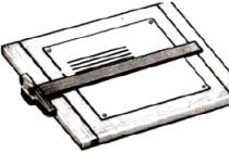
This constructor consists of a printed circuit board 20x55mm in size and, accordingly, a set of necessary radio components. The board shows the installation locations of all components and their ratings, so there are no particular difficulties with installation.
The entire manufacturing process and the operation of the circuit can be viewed in the video:
List of tools and materials
- a set of running lights on a CD4017 or K561IE8 chip ();
-screwdriver;
- scissors;
- soldering iron;
- cambric;
-accumulator battery from a cell phone;
- 12V power supply;
- connecting wires;
- foil textolite for printed circuit board;
- K561TM2 microcircuits;
-resistors;
- KT815 transistors (or analogues);
-LEDs.
Step one. PCB desoldering kit from AliExpress.
All that is needed is to solder the components of the kit to the board. In view of the miniature size of SMD radio elements, I used a "third hand" with a magnifying glass. First, I soldered resistors, capacitors and other circuit components except for microcircuits. At the end, we solder the microcircuits and LEDs.
This circuit operates from 3 to 15V. The pulse generator is assembled on a NE555 chip, then the pulses are fed to a decimal counter with a decoder - a CD4017 chip (K561IE8), to ten outputs of which LEDs are connected through current-limiting resistors. The switching speed of the running lights is regulated by a tuning resistor.
Constructor schema.

My circuit worked the first time I turned it on.

step two. Modernization of the scheme of running lights.
Later, during the experiments, the CD4017 chip failed. On a quick wire, I had to replace it with a domestic analogue K561IE8.
I wanted to get more interesting lighting effects of running lights. As a result, I collected another printed circuit board with K561TM2 triggers and power keys on KT815. A pulse from each K561IE8 output is fed to the trigger input according to the "latch" principle, that is, at the trigger output, the signal remains constant until the reset pulse arrives from leg 11 of the CD4017 (K561IE8) microcircuit. 9 channels will turn on per cycle. Power switches on KT815 transistors are designed to connect loads up to 1-1.5A. If you need to connect a more powerful load, then you need to replace the KT815, respectively, with more powerful transistors. Since I used four K561TM2 microcircuits, I got a circuit for eight channels. In this circuit, you can get 9 LED control channels, but then you need to add another K561TM2 chip to the circuit by connecting one trigger (the K561TM2 chip consists of two triggers), and also add one transistor switch.
Schematic after modification.


To check the work, I connected pieces to each of the eight channels led strip with three LEDs.

I replaced the 50kΩ trimmer with 470kΩ to expand the range of pulse frequency adjustment. Found in
Quite often, car owners seek to arrange them in a special way. One possible solution to this problem is the use of LED turn signals. In addition to such an application, this semiconductor element can be used in car lighting, exterior design (for example, parking lights).
Some go even further and install them inside the cabin to express greater individuality. One example of this use could be at the door. When stopped, they turn on, the driver or passenger can easily leave the vehicle.
Video: do-it-yourself VAZ LED turn signals
LED types
An LED is a semiconductor radio component that, under the influence of an electric current, begins to glow. The main element in them is silicon. Depending on the type of impurity used in this semiconductor element, the LED can change its light.
The following types of such microelectronic components are most commonly used:
- Aluminum, gallium, nitrogen are used as an impurity. Depending on the concentration, the color range changes from blue to green.
- Based on indium, helium, phosphorus. The color can range from red to yellow.
Today, the semiconductor industry produces LEDs in all possible colors. Therefore, there are no problems with this.
One LED is unlikely to be able to illuminate the turn signal, but several can easily cope with this task.
By power, they are divided into low-power and power. Power ones are designed for a current of more than 0.35 A. In turn, low-power ones work up to this value.
Possible connection schemes
To date, the following LEDs are most commonly used:
- A similar connection is used to switch a long chain of LEDs (for example, around the perimeter of a car). A capacitor-type power supply is used as a voltage source. The current-limiting element in such a circuit is a capacitor. as a converter AC voltage in a constant, a diode bridge is used in combination with a filter (usually a set of a resistor and a capacitor). Be sure to install a protective resistor in series with the diode chain, which takes on excess voltage.
- The second option is to connect the LEDs into garlands of 3-6 pieces in series. Several such garlands can be connected in parallel to each other, depending on the power source. The role of the latter in this circuit is played by a stabilized power supply with a voltage of 12-24V. In such a circuit, a protective resistor is also required to be installed in series with each garland.
- The last, third connection option is directly. In such a circuit, only a power diode can work, which is designed for a current of more than 0.35A.

The LED has only two legs for connection - the anode and the cathode. The anode must be connected only to the positive pole of the power source. In turn, the cathode to the negative. With another connection, this semiconductor element will not work.
Requirements for the performer and instrument
When carrying out any electronic installation, a tester (for measurements), a soldering iron, tweezers, side cutters (if they are not available, you can use pliers that can also perform this task) are used. To perform calculations and determine the required values, you will need a calculator. Among the consumables, fiberglass can be distinguished (a printed circuit board is made from it - the basis for attaching this semiconductor element), solder, rosin, flux for soldering and zaponlak.

It will be difficult to make LED turn signals without a tester
Selection of the most suitable series of elements
The main parameters of any device of this series are the rated voltage. That is, the working values of these parameters, at which the LED retains its original properties. The calculation is made according to Ohm's law for the circuit section. Each car has a power source with given parameters- current and voltage. On the other hand, we have the characteristics of the required LED. The difference between the first and second values will be the characteristics of the resistor that must be connected in series in the circuit. And knowing the parameters of the latter, the entire circuit can be assembled without much difficulty.
Let's carry out the calculation for the simplest circuit, which consists of a stabilized voltage source, an LED and a protective resistor. In other cases, the technique remains practically the same, but only due to the larger number of elements used, the calculation becomes more complicated.

For example, in a car there is a source whose values are respectively 0.02A and 24V. Moreover, a constant voltage source (for example, a battery). It is necessary for the LED to receive 0.02A and 2V. Now we determine the value of the potential drop across the resistor:
UR= Upit-Ud,
where UR is the potential drop across the resistor, V
Upit – power supply voltage, V
Ud - nominal (working) potential drop across the diode, V
Using the formula above, we get UR=24-2=22V. All elements of this circuit are connected in series. As a result, the current does not branch anywhere, at any point in the circuit it will be equal to 0.02A. As a result, we obtain the resistance value of the resistor according to Ohm's law:
where R is the resistance of the resistor, Ohm
IR - current in the circuit, A
Substituting the necessary values, we get R = 22 / 0.02 = 1100 Ohm. Next, we determine the second most important parameter of any resistor - this is power. It is determined by the formula:
The result is PR \u003d 0.02 * 22 \u003d 0.44W. From the existing series of resistors, select the nearest highest values- 1.1 kOhm and 0.5 W. On this, we can consider the calculation completed - the parameters of all elements electrical circuit defined.
One example of using LEDs
One of the most common uses of these elements in cars is as a. Now let's look at how to make LED turn signals out of ordinary ones.
The procedure is as follows:
- The most suitable connection scheme is selected
- The required LED is selected
- Next, all other radio components of the electrical circuit are calculated
- Based on the calculations, protective resistors and other components are selected
- Then a list of necessary radio components is compiled. With this list, you need to visit the nearest store of this profile and buy all the necessary equipment in it
- All necessary documentation is being developed (including the printed circuit board drawing and its assembly drawing)
- Then you need to make a printed circuit board for mounting radio components on it. To do this, a pre-designed pattern is applied to the fiberglass board using varnish. All necessary holes for mounting radio components are drilled. It is immersed in ferric chloride. After the drawing on the board is etched, it goes. Washable with plain water. The protective layer is then removed with a solvent. The next step is again rinsing with running water. And only after that it dries. Upon completion of all the procedures performed, we receive a ready-made board for further work. Since there are only 4 turn signals, then 4 boards must also be made.
- At the next stage, based on the diagram and the developed drawing of the board, all elements of the circuit are mounted. At the end of the assembly, all contacts must be opened with a zaponlak (it will provide the necessary insulation and protection of the circuit in case of moisture getting here)

- Then you need to dismantle the old turn signals and carefully disassemble them. And so as not to damage.
- The old lighting element (lamp) is completely turned off and removed.
- The joints, where everything was previously filled with glue, must be cleaned with a needle file and sandpaper. Then this joint is degreased with alcohol. Then all this is washed with water and should dry.
- In place of the old lighting element, new ones are installed. If necessary, minor structural changes can be made to simplify the installation process.
- Then the assembly is carried out in the reverse order. It is necessary to apply glue to the joint and glue the disassembled turn signal. Then you need to wait until the glue hardens. In the future, this turn signal is installed in the old place and old wires are connected to it.
- The next step is to make changes to the . To do this, the old wires are broken and an additional stabilized power source is wedged into it (you can purchase it separately or make it yourself). Moreover, its output is set to the LED. Voltage is supplied to the input from the contact group of the intermediate relay. It is most convenient to place this element in dashboard car. At the final stage, it is necessary to check the polarity of the connection visually. The anode must be connected without fail only to the positive pole of the power source. In turn, the cathode to the negative. With a different connection, this semiconductor element will not work, and may even fail.
- Then you need to inspect assembled circuit and compare it with the initial version for compliance.
- Next, power is applied and the operability of the circuit is checked. If everything is fine, then the installation is complete. Otherwise, you need to find the cause of the malfunction and eliminate it.
Video: homemade turn signals
Conclusion
This article discusses how to make LED turn signals on your own. There is nothing complicated about this, and with sufficient qualifications and well-prepared preliminary work, it can be done without any problems. Due to such a circuit upgrade, you can achieve significant savings in battery life and significantly extend its service life.
- news
- Workshop
The Mercedes-Benz E-class coupe was spotted during tests. Video
The video featuring the new Mercedes-Benz E Coupe was filmed in Germany, where the car is undergoing final testing. The video was posted on the walkoART blog, which specializes in spy footage. Although the body of the new coupe is hidden under a protective camouflage, we can already say that the car will receive a traditional appearance in the spirit of the Mercedes E-class sedan...
Study: Automobile exhaust is not the main air pollutant
According to the participants of the energy forum in Milan, more than half of CO2 emissions and 30% of particulate matter harmful to health enter the air not at all because of the operation of internal combustion engines, but because of the heating of housing stock, reports La Repubblica. Currently, in Italy, 56% of buildings belong to the lowest environmental class G, and ...
New generation Ford Fiesta: already in 2018-2019
The appearance of the novelty will be made in the style of the larger Focus and Mondeo of the current generation. This is reported by OmniAuto, citing sources within the company. Based on the information received, the publication's artist also created an image on a computer showing what such a car could look like. Mondeo-style headlights and grille aren't the only things...
Mercedes plant in the Moscow region: the project is approved
Last week it became known that the Daimler concern and the Ministry of Industry and Trade are planning to sign a special investment contract, which involves the localization of the production of Mercedes cars in Russia. At that time, it was reported that the site where it was planned to launch the production of Mercedes would be the Moscow region - the Esipovo industrial park under construction, which is located in the Solnechnogorsk region. Also...
Video of the day: Electric car hits 100 km/h in 1.5 seconds
An electric car called Grimsel was able to accelerate from standstill to 100 km / h in 1.513 seconds. The achievement was recorded on the runway of the air base in Dubendorf. The Grimsel is an experimental vehicle developed by students at the ETH Zurich and the Lucerne University of Applied Sciences. The car was built to...
Self-driving taxis coming to Singapore
During testing, six modified Audi Q5s capable of autonomous driving will hit the roads of Singapore. Last year, such cars easily covered the path from San Francisco to New York, according to Bloomberg. In Singapore, drones will move along three specially prepared routes equipped with the necessary infrastructure. The length of each route will be 6.4 ...
Citroen is preparing a suspension-type carpet-flying
In the Advanced Comfort Lab concept presented by Citroen, built on the basis of the C4 Cactus serial crossover, the most noticeable innovation is, of course, plump chairs that look more like home furniture than car seats. The secret of the chairs is in the padding of several layers of viscoelastic polyurethane foam, which is usually used by manufacturers ...
Suzuki SX4 survived restyling (photo)
From now on, in Europe, the car is offered only with turbocharged engines: petrol liter (112 hp) and 1.4-liter (140 hp) units, as well as a 1.6-liter turbodiesel that develops 120 horsepower. Before modernization, the car was also offered with a 1.6-liter 120-horsepower naturally aspirated gasoline engine, but this unit will be retained in Russia. In addition, after...
Run Magadan-Lisbon: there is a world record
They traveled across Eurasia from Magadan to Lisbon in 6 days 9 hours 38 minutes and 12 seconds. This race was organized not only for the sake of minutes and seconds. He carried a cultural, charitable and even, one might say, scientific mission. Firstly, 10 eurocents from each kilometer traveled was transferred to the benefit of the organization...
The iconic Toyota SUV will sink into oblivion
The complete cessation of production of the car, which has so far been produced for the markets of Australia and the Middle East, is scheduled for August 2016, according to Motoring. For the first time, the serial Toyota FJ Cruiser was shown in 2005 at the New York International Auto Show. From the start of sales until today, the car was equipped with a four-liter gasoline ...
HOW to order a car from Japan, a car from Japan in Samara.
How to order a car from Japan Japanese cars are leaders in sales all over the world. These machines are valued for their reliability, quality, maneuverability and trouble-free repair. Today, car owners want to be sure that the car came directly from Japan, and ...
Which car to choose a family man
A family car should be safe, roomy and comfortable. In addition, family cars should be easy to use. Varieties of family cars As a rule, most people associate the concept of "family car" with a 6-7-seat model. Universal. This model has 5 doors and 3...
Rating of reliable cars 2018-2019Reliability, of course, is the most important requirement for a car. Design, tuning, any "bells and whistles" - all these trendy tricks inevitably pale in importance when it comes to vehicle reliability. The car should serve its owner, and not cause him problems with his own ...
HOW to choose and buy a car, Buying and selling.
How to choose and buy a car The choice of cars, both new and used, on the market is huge. And not to get lost in this abundance will help common sense and a practical approach to choosing a car. Do not give in to the first desire to buy the car you like, carefully study everything ...
What did the stars drive in the 20th century and today?
It has long been understood by everyone that a car is not just a means of transportation, but an indicator of status in society. By car, you can easily determine which class its owner belongs to. This applies to both the common man and pop stars. ...
The cheapest car in the world - TOP-52018-2019
Crises and the financial situation are not very conducive to buying a new car, especially in 2017. Only everyone has to drive, and not everyone is ready to buy a car in the secondary market. There are individual reasons for this - to whom the origin does not allow to travel ...
How to choose a car brand When choosing a car, you need to study all the pros and cons of the car. Look for information on popular automotive sites where car owners share their experiences and professionals test new products. Having collected all necessary information you can decide in...
2018-2019: CASCO rating of insurance companiesEvery car owner strives to protect himself from emergencies related to road accidents or other damage to your vehicle. One of the options is the conclusion of a CASCO agreement. However, in an environment where there are dozens of companies providing insurance services in the insurance market, ...
Which sedan to choose: Almera, Polo Sedan or Solaris
In their myths, the ancient Greeks spoke of a creature that had the head of a lion, the body of a goat, and a snake instead of a tail. “The Winged Chimera was born from a tiny creature. At the same time, she sparkled with the beauty of Argus and horrified the ugliness of the Satyr. It was a monster of monsters." At the word...
- Discussion
- In contact with
Many car enthusiasts to improve appearance of their car, tune their “Swallow” with LED lights. One of the tuning options is a running turn signal, which draws the attention of other road users to itself. The article provides instructions for installing and configuring turn signals with running lights.
[ Hide ]
Assembly instructions
LED lamps are semiconductor elements that glow under the influence of an electric current. The main element in them is silicon. Depending on what impurities are used, the color of the bulbs changes.
Photo gallery "Possible options for dynamic direction indicators"
Tools and materials
To make a running turn signal with your own hands, you will need the following tools:
- soldering iron;
- side cutters or pliers;
- soldering iron and soldering material;
- tester.
From consumables you need to prepare fiberglass. It is needed for the manufacture of a printed circuit board on which a semiconductor element will be placed. The required LEDs are selected. Depending on the characteristics of the LEDs and the current and voltage values of the on-board network, the characteristics of the protective resistors are calculated. Using calculations, the rest of the network components are selected (the author of the video is Evgeny Zadvornov).
Work sequence
Before you make turn signals, you need to choose the right scheme.
Then, based on the scheme, make a printed circuit board and apply markings on it to accommodate future elements.
The assembly consists of a sequence of actions:
- First, turn off the power to the car by disconnecting the negative terminal from the battery.
- Next, you need to remove the old direction indicators and carefully disassemble them.
- Old light bulbs should be unscrewed.
- The joints should be cleaned of glue, degreased, washed and allowed to dry.
- In place of each old element, a new turn signal running fire is installed.
- Further assembly and installation of lamps is carried out in the reverse order.
- After installation, the wires are connected.
At the next stage, an additional stabilized power source is included in the network. Power is supplied to its input from an intermediate relay, and the output is connected to a diode. It is better to place it in the dashboard.
When connecting LEDs, it is necessary to ensure that the anode is connected to the plus of the power source, and the cathode to the minus. If the connection is not made correctly, the semiconductor elements will not glow and may even burn out.

Features of installation and adjustment of running direction indicators
Can install dynamic turn signals instead of conventional LEDs. To do this, they remove, dismantle the board with LEDs and current-limiting resistors. On the repeater, you need to tear off the glass from the body. The reflector should then be carefully cut out and removed.
In place of the remote reflector, an SMD 5730 board is installed, on which yellow LEDs are located. Since the repeater has a curved shape, the board will have to be stratified and slightly bent. At old board you need to cut off the part with the connector and solder it to connect the controller. Then all components are returned to their place.
To adjust the time of running LED lights, a switch is soldered to the microcontroller. When a suitable speed is found, jumpers are soldered in place of the switch. When connecting two terminals to ground, the minimum time between LED flashes will be 20 ms. When the contacts are closed, this time will be 30 ms.

Issue price
You can make a turn signal running fire from daytime running lights. Their cost is 600 rubles. As light sources in this case, you can take "pixel" RGB LEDs in the amount of 7 pieces for each running turn signal. The cost of one element is 19 rubles. To control the LEDs, you need to purchase an Arduino UNO worth 250 rubles. Thus, the total cost will be 1060 rubles.
He said last year "Gop" - it's time to jump :)
Or rather, to do the promised review of running turn signals.
I ordered 1 meter of black tape WS2812B (144 LEDs) in a silicone tube, when ordering I chose “Black 1m 144led IP67” (maybe someone will like the white color of the substrate, there is such a choice).
A small caveat
I received a tape soldered from two half-meter pieces. The downside of this is the weak point of the soldering (contacts may break over time) and the increased gap between the LEDs.
Check with the seller before buying 
Contact wires were soldered to the tape on both sides for serial connection of several pieces, because I didn’t need it, then I soldered it off on one side of the wire, sealed everything with a neutral sealant and wound some more black electrical tape.


Attached to glass with double-sided transparent adhesive tape, for example,.
Installation details
I degreased the surfaces, first glued the adhesive tape to the tube (I will call it that, even though the cross section is rectangular), cut off the protruding excess of a wider tape, pushed the edges of the tube into the gap between the ceiling and the upper parts of the decorative panels of the rear pillars (I hid the contact wires with the connector behind one panel ), centered and began to press against the glass, slowly pulling out the protective layer of the tape.
Unfortunately, there is no video - there were no free hands for shooting, and everyone's cars are different.
If something is not clear - ask in the comments.
The summer heat test was successful - nothing peeled off or floated.
The only negative is that the angle of inclination of the glass is gentle, the LEDs shine more upwards. On a sunny day it is hard to see, but since these are duplicate signals, then 
Now let's move on to the electronic stuffing.
I used but recently discovered
For about the same cost, we get more buns
The sketch will work without any modifications on Wemos when programming in the Arduino IDE, and if you implement a small web server, then when you connect to it via Wi-Fi, you can change the values \u200b\u200bof variables such as the delay time between blinks, the amount of deceleration during emergency braking etc.
Here in the future, if someone is interested in implementing a project on ESP8266, I can post an example for changing settings via the web interface, saving them to EEPROM, and then reading.
The launch of the web server can be implemented, for example, by turning on the turn signal and pressing the brake pedal when the ignition is turned on (in the setup procedure, poll the status of the corresponding inputs).
To implement the flashing mode during heavy braking was purchased
The sketch monitors the level of deceleration when the brake pedal is pressed, if it exceeds 0.5G (hard deceleration, but no brake squeal), then a flashing mode is activated for a few seconds to attract additional attention.
The control signals to the Arduino inputs from the “plus” of the stops, turn signals and reverse are fed through galvanic isolation - optocouplers with current limiting resistors, which eventually form the LOW level at the Arduino inputs (constantly pulled to the plus through 10kΩ resistors).
Power - 5 volts through a DC-DC buck converter.
The whole thing is folded like a sandwich and packed in a suitable box, on which I marked the installation direction with an arrow for the correct orientation of the gravity sensor
Scheme and photo

The value of the pull-up (to plus) resistors is standard - 10 kOhm, the optocoupler current-limiting resistors - 1 kOhm. Optocouplers dropped out of old boards, two got PC123, two - PC817. 
In the first photo you can see two additional pins, I made them for the turn signals. Since in my car, when the steering column lever is turned on, a short to ground occurs, I connected the wires to the lever block and the Arduino inputs. If the steering column switch switches plus or take a signal from the "+" bulbs of the left / right turn signal, then connect them through a galvanic isolation. 

Well, now the sketch itself (Arduino IDE)
#include
I tried to comment on it to the maximum, but if there are questions, I will try to add comments (therefore, I place it in the text of the review, and not as an attached file). By the way, this also applies to other points of the review - I will also supplement it if there are significant questions in the comments.
And finally, a demonstration of work (I used a sketch with a demo mode for the video).
Upd. I made a sketch with a demo mode specifically to fit everything into one short video.
The brake light flashes only during heavy braking (this was described above), when it is smooth and standing in traffic jams, it simply burns without annoying drivers from behind.
Brightness in the dark is not excessive, because. because of the tilt of the glass, the lights are directed more upwards than backwards.
Regular lights work as usual, this strip duplicates them.
I plan to buy +97 Add to favorites Liked the review +89 +191
The designer of running lights from Aliexpress is a printed circuit board and a set of radio components. All you need to do is solder the components to the board.
But from it you can get more interesting effects of running lights. For example, for car turn signals or in a stop signal or just on garlands for a holiday.

This circuit can operate in the supply voltage range of 3-15 Volts. The pulse generator is assembled on a NE555 chip, then the pulses are fed to a decimal counter with a decoder - a CD4017 (or K561IE8) chip, to the outputs of which LEDs are connected through current-limiting resistors.
The switching speed of the running lights is regulated by a tuning resistor. Add a circuit with flip-flops and output transistor switches. No programming required, etc. As a result, more interesting lighting effects of running lights can be obtained. You need to make another printed circuit board with K561TM2 triggers and power keys on KT815. A pulse from each K561IE8 output is fed to the trigger input according to the “latch” principle, that is, the signal at the trigger output remains constant until the reset pulse arrives from pin 11 of the CD4017 (K561IE8) chip. 9 channels are switched on per cycle.