The acoustic generator is designed to induce interference in places of confidential negotiations. It produces "white" noise over the entire audio frequency range. Acoustic vibrations are transmitted by means of piezoelectric vibrators and acoustic columns

This transmitter is designed to transmit telephone conversation information to a VHF receiver in the range of 68-108 MHz. The range of the repeater is 50-100 m
The scheme considered in detail is very easy to repeat by any novice radio amateur and is capable of registering vibrations of walls up to 0.5 m thick or a whole riser of radiators

Usually, radio bugs operate at the same frequency in the range of 30 ... 500 MHz with a low radiation power of no more than 5 mW. More advanced radio bookmarks can work in standby mode and start broadcasting when there is a threshold noise level, which makes them less likely to be detected. Many radio bugs like to "dwell" in telephone or 220 V sockets as they do not require their own power source
A selection of simple home-made designs of radio bugs powered by one 1.5 volt cell, with a very low current consumption. Such a radio tab can work in an autonomous mode for a very long time with the transmission of a radio signal over a distance of 30-60 meters.
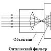
This method of protection against laser devices consists in using special devices to make the vibration amplitude of the glass much larger than that caused by the human voice. At the same time, difficulties arise in the detection of a speech signal on the receiving side.
An excellent selection of good circuitry solutions for television video transmitters for wireless transmission of video signals from camcorders, satellite receivers, game consoles and many other devices. Video transmitter circuits operate in the standard frequency range of 470-580 MHz and can be received from channels 21-34 by almost any TV. The video signal can be transmitted over a distance of 50-100 meters using a short antenna made of a common piece of copper wire.
The presence of a video camera in modern realities is not particularly surprising to anyone. It can be used to reflect the important moments of our life, the life of our relatives or friends, as well as our competitors in our professional life. In this overview article, we will consider the basic schemes and connection methods for different purposes, their advantages and disadvantages.
In order to exclude the work of a mobile phone and mobile Internet in some places, for example, in theaters or educational institutions, during exams, you can use homemade GSM signal jammers for cell phones.
This bug scheme is recommended for repetition for novice radio amateurs and young spies. Firstly, it is not difficult to assemble, it consists only of available radio components and is powered by a 9-volt crown battery. The radius of its action is up to 200 meters, in urban conditions it may be less, it all depends on the transistor used in the bug. The scheme was borrowed from an English-language site, but it is fully functional, because it has been tested in the assembly.
TRANSMITTERS - "SPIES"
We bring to your attention several designs of miniature transmitters.
Necessary devices and tools:
1. Amperevoltmeter (AVOmeter) with a linear scale (pointer) with measurement limits of 30V, 150V, 15V, current 15 Ma, 150 Ma.
2. Wavemeter - the diagram is shown below:
The L1 coil contains 4.5 turns of wire with a diameter of 1-1.5 mm, wound on a mandrel with a diameter of 16 millimeters. The branch is made from 2 turns. A piece of coaxial cable was used as an antenna. The braid and the inner core are soldered together. The length of the segment is 100 millimeters. Microammeter - 50-100 microamperes. Structurally, the wavemeter is carried out in a metal case.
It is better to calibrate the wavemeter using a high-frequency generator, but you can use an auxiliary generator and a radio receiver with a digital scale for this purpose. The generator can be assembled according to one of the schemes described below. First, on the scale of the receiver, we find the frequency of the auxiliary generator, then we tune the wavemeter to the same frequency and make a mark opposite the pointer of the wavemeter capacitor. So we consistently perform all the calibration for operating frequencies in the range of 88-108 megahertz.
3. Control transmitter.
The schematic of the monitoring transmitter is shown below:

This transmitter is assembled according to a typical scheme and has maximum repeatability.
About the details: The microphone is of the MKE-332 ... 333A type, the transistor is KT3102A-B, KT315 can be used, but they have a large spread in the generation current. The coil has 6 turns, the PEV 0.45-0.7 wires on a 6 mm blank (winding - close), a tap - from 2 turns (counting from the top according to the diagram). The frequency of the assembled circuit is 82 ... 90 Megahertz. The frequency is changed with a variable capacitor. Antenna is a piece of stranded wire, 200-260 mm long.
Setting: Connect the power supply (9 volts!), Turn on the milliammeter in series with the source. Consumption current should be in the range of 8-10 milliamperes. The selection of the current consumption is carried out using the resistor R2. Next, we connect the antenna and tune the transmitter to the desired frequency.
The test transmitter can also be used for pre-selection of transistors (for mass production). To do this, you need to solder the socket to the place where the transistor is connected and insert the tested transistor into it (it is clear that before changing the transistor, you must definitely turn off the power source!).

Transistors are selected for the same current consumption. It is also useful to use several (for example, 43, 51 and 62 kilohms) resistors and a switch for the appropriate number of positions in place of the resistor R2. Later, during mass production, in place of this resistor, a rating corresponding to the optimal one for a given transistor instance is soldered. To make a transmitter in one copy, you do not need to do a preliminary check of the transistor, but then you may have to select a resistor in a finished structure - and this is not very convenient, given the miniature design ...
4. Tools for assembly work (tweezers, wire cutters, soldering iron with accessories).
5. Materials: foil-clad fiberglass, winding wire, paraffin - for fixing the turns of the coils after tuning, varnish of the "tsapon" type.
A little about antennas: in the descriptions, the designations of the antenna A1 and A2 will be found. Antenna A1 is a piece of wire about 300 millimeters long, antenna A2 is a piece of wire about 1 meter long.
A typical transmitter circuit with an A2 antenna provides a communication range in the city - up to 500 meters (manufacturer's data). For the transmitter to operate at a fixed frequency, the capacitor C6 is replaced with a constant capacitor of the corresponding rating.
The high power transmitter circuit is shown below:

The operating range of the transmitter with the A2 antenna is 1-1.2 kilometers at a power supply voltage of 9 volts. The consumed current is about 28 milliamps.
This transmitter consists of a standard one and is supplemented by a power amplifier on a VT2 transistor. The circuit is characterized by increased frequency stability and less dependence on external factors. This allows the transmitter to be worn on the body ...
About details: L1 - 6 turns, wire 0.47, on a mandrel, 3.5 mm in diameter, L2 - 4 turns, on a mandrel 2 mm, wire 0.3 mm in diameter. L3 - on a 2.7 mm mandrel - 7 turns, wire diameter - 0.3 mm. When arranging the transmitter, place the coils L1 and L3 mutually perpendicular! The L2 coil is placed inside the L1 coil. The rest of the details are the same as in a typical transmitter.
Setting: First, we set up the master oscillator on the transistor T1 - by changing the value of the resistor R2 we achieve a consumption current of 10 ma. Next, we collect the output stage on the T2 transistor. With the antenna connected, by moving the L2 coil, we achieve a consumption current of about 26-28 mA. Further, according to the wavemeter, we achieve the maximum output power (by a selection of loop capacitors - roughly and by moving the turns of the coils apart - smoothly).
The telephone line powered transmitter is shown below:

To operate in telephone lines, the transmitter must have a consumption current of 10-12 ma in lines without a blocker and 16-18 ma in lines with a blocker. The transmitter is assembled according to a typical scheme. To obtain the desired consumption current, it is necessary to put transistors in the circuit with a selected consumption current of 7-8.5 mA with a base resistor that is 2 times smaller than the one that was used to select the transistor. A microphone is not needed in this circuit. Modulation is carried out by the power supply during a call ... The transmitter adjustment does not differ from the typical one. The capacity of the capacitor C2 is 0.022 microfarads. A few words should be said about the antenna design. For the manufacture of the antenna, a piece of insulated single-core wire, 210-240 mm long, was used. At one end, the insulation is stripped for soldering. A piece of winding wire, approximately 200 mm long, is soldered to the stripped end and winding is performed on the main antenna wire, approximately 20 mm wide in several layers. The opposite end of the wire is soldered into the circuit. After manufacturing, the winding should be secured. It turns out an antenna with a distributed inductance. This measure made it possible to significantly reduce the size of the antenna practically without reducing the radiated power (in this design, for obvious reason, they strove to obtain the smallest possible size). The range in the city (declared by the manufacturer) is 200-350 meters. The transmitter turns on when you go off-hook.
The coil L1 of the transmitter is wound on a 3 mm blank, turn to turn and contains 6 turns, wires with a diameter of 0.3-0.4 mm. The setting is practically the same as that of a typical transmitter. We adjust the frequency by selecting a loop capacitor and expanding the coil turns.
The FET transmitter circuit is shown below:

The circuit has lower power consumption. The selection of transistors is not needed. The output power is equal to the output power of a typical transmitter at half the current consumption. Frequency drift when the supply voltage changes from 3 to 9 volts - no more than 0.2 megahertz (declared by the manufacturer). Coil parameters are the same as in the basic transmitter circuit. Antenna tap is made from the second loop. The circuit can be used both as an independent transmitter and as a master in a more powerful one (similar to the transmitter circuit with increased output power).
All of the above transmitters operate in the 88-108 megahertz frequency range (FM band). For tuning to the FM range (64-72 megahertz), the number of turns of the loop coils must be increased by 1.4 times. The length of the antennas should also be increased by 1.4 times. It is possible not to increase the antenna length, but this will somewhat reduce the range of the transmitters.
A few words should be said about the installation. To give the structure sufficient rigidity and reliability, all transmitters should be made on printed circuit boards. When designing a printed circuit board, you should strive to keep all conductors to a minimum. The length of the leads of the parts is reduced to the minimum possible. It is theoretically possible to manufacture a transmitter according to a typical scheme on a board with an area of no more than 1 square centimeter. After adjustment, the transmitter should be coated 2-3 times with quick-drying varnish - to increase the rigidity of the structure. It is better to make the coating by dipping (you must first solder all external conductors). The length of the power and microphone wires should also be kept to a minimum. It is useful after assembly to place the transmitter in a sealed metal casing, which should be connected to the common ("minus") conductor of the board at one (!) Point. All these measures improve the reliability of the transmitter during operation.
Free download the book:
"Spy passions. Dual-use electronic devices"
Schematic diagrams, descriptions, design and operation features of small-sized dual-use transmitting and receiving means, used both for communication purposes and for unauthorized access to confidential information - electronic espionage, are given. More than 200 diagrams of devices and assemblies are presented, the joint use of which makes it possible to create more than a thousand electronic structures. On the example of the simplest experiments, possible ways of intercepting information on some channels of its formation, processing and transmission (sound, radio, telephone, computer) are described. Simple recommendations are given for the protection of information. The book is designed for a wide range of readers who design communications, as well as those who are interested in the possibilities of electronics and are concerned with protecting their own and other people's secrets.
The development and use of the achievements of modern electronics led to the emergence of new radioelements and devices based on them with new (often unique) remarkable parameters and consumer properties. The widespread introduction of these elements and devices, especially in 5yt, led to a radical transformation of living conditions.Highly sensitive high-quality small-sized radios, televisions, tape recorders appeared. The possibilities of modern personal computers are amazing. Audio and video, laser dis- \ I, multimedia, virtual reality - new concepts, new possibilities, a new level that improves the quality of life. Communications have entangled the entire world. This is accompanied by a significant expansion of communication services. Through a computer, you can watch TV programs, listen to the radio, make purchases without leaving your home, and almost instantly communicate via the internet or similar systems anywhere in the world. The air is crowded: DV-, V-, HF-, VHF-devices, - there is not enough space for television channels. Satellite and cable systems, radio and fiber-optic communication lines are becoming commonplace. And a cellular radiotelephone no longer seems to be something All this is amazing.
However, the wonders of electronics can cause more than delight.
A radio transmitter as a means of communication expands the capabilities of not only ours, our friends, colleagues and partners. For a number of users of modern microelectronic products, some goals and methods of achieving them may not only be honest and noble. And they not always look only at the TV and computer, or at the spyglass at the stars and beauties of the firrods, but, unfortunately, also at the keyholes. And they listen not only to their own phone, but also to someone else's - and not out of idle curiosity caused by a lack of tact and culture. And the damage from all this can be not only moral, but also economic.
Information gains value and becomes a commodity. And as a product it is produced, stored, sold. And as a product it is stolen, copied and resold without the permission of the legal owner, violating his rights and causing him economic damage.
And all this is called - industrial, more precisely economic, espionage, carried out, as a rule, using all the achievements of modern microelectronics: amplifiers, receivers, transmitters, repeaters, tape recorders, televisions. They eavesdrop, spy on, intercept messages. All used channels of information transmission can be monitored: sound, telephone, radio, etc.Currently, many special electronic means are offered for unauthorized access to someone else's information - for electronic espionage. Such devices differ in technical parameters, consumer properties, price. In most cases, the design of these tools, as a rule, is based on fairly simple principles and circuitry solutions.
Some diagrams of such radio-electronic devices or their individual fragments will be given and described below, recommendations for design and adjustment will be given. However, the goal is not to stimulate the "enthusiasts" of industrial electronic espionage (or intelligence - whoever likes which better). The goal is to illustrate the capabilities of modern microelectronics, the achievements of which can be used for various purposes.
Using high quality elements and modern circuitry solutions, you can create highly efficient and compact communication facilities. However, on the basis of the same elements and the same schemes, it is possible in a matter of minutes (or hours) with average qualifications, “on the knees”, to create electronic espionage devices.
For those who are concerned about the protection of secrets - theirs or others, small or large, personal or industrial - this material is intended. It is also intended for those who, without violating legal and moral laws, would like to get acquainted with some circuitry solutions and use them to repeat some of the given devices or create their own radio designs, of course, for communication purposes.
Basic elements of transceivers
Antenna amplifiers (radio and TV), antennas
Antennas at a glance
Antennas for transmitters
Using meter indicators
Antennas for receivers
AM and FM radio converters
VHF- FM- and AM-radio receivers
FM and AM radio transmitters
Walkie-talkie (transceivers)
Alternative means of communication
Telephone repeaters
General issues
Unconventional use of radio equipment
Power supply for stationary and autonomous devices
Protection of information
Professional means of information protection
Basic stationary means of information protection
Search equipment