Hello. This article is about the BIOS setup utility, which allows the user to change basic system settings. Settings are stored in non-volatile CMOS memory and are retained when the computer is turned off.
ENTERING THE SETUP PROGRAM
To enter the BIOS setup utility, turn on the computer and immediately press the . To change additional BIOS settings, press the combination “Ctrl+F1” in the BIOS menu. The BIOS advanced settings menu will open.
CONTROL KEYS
<
?>
Go to previous menu item
<
?>
Move to next item
<
?>
Move to item on left
<
?>
Go to the item on the right
<+/PgUp>
Increase the numerical value of the setting or select another value from the list
<-/PgDn>
Decrease the numerical value of the setting or select another value from the list
REFERENCE INFORMATION
Main menu
A description of the selected setting appears at the bottom of the screen.
Settings Summary Page / Settings Pages
When you press the F1 key, a window appears with a brief hint about possible configuration options and the assignment of the corresponding keys. To close the window, click
Main menu (using the example of BIOS E2 version)
When you enter the BIOS setup menu (Award BIOS CMOS Setup Utility), the main menu opens (Fig. 1), in which you can select any of eight settings pages and two options for exiting the menu. Use the arrow keys to select the desired item. To enter the submenu, press
Fig.1: Main menu
If you can't find the setting you need, press "Ctrl+F1" and look for it in the BIOS advanced settings menu.
Standard CMOS Features
This page contains all standard BIOS settings.
Advanced BIOS Features
This page contains additional Award BIOS settings.
Integrated Peripherals
This page configures all built-in peripheral devices.
Power Management Setup
This page allows you to configure energy saving modes.
PnP/PCI Configurations (Configuring PnP and PCI resources)
This page allows you to configure resources for devices
PCI and PnP ISA PC Health Status (Computer health monitoring)
This page displays the measured values of temperature, voltage and fan speed.
Frequency/Voltage Control
On this page you can change the clock frequency and processor frequency multiplier.
To achieve maximum performance, set the “Top Performance” item to “Enabled”.
Load Fail-Safe Defaults
Secure default settings ensure system functionality.
Load Optimized Defaults
The default optimized settings provide optimal system performance.
Set Supervisor password
On this page you can set, change or remove your password. This option allows you to restrict access to the system and BIOS settings, or only to the BIOS settings.
Set User password
On this page you can set, change or remove a password that allows you to restrict access to the system.
Save & Exit Setup
Saving settings in CMOS and exiting the program.
Exit Without Saving
Cancels all changes made and exits the setup program.
Standard CMOS Features
Fig.2: Standard BIOS settings
Date
Date format:<день недели>, <месяц>, <число>, <год>.
Day of the week - the day of the week is determined by the BIOS based on the entered date; it cannot be changed directly.
Month - the name of the month, from January to December.
Number - day of the month, from 1 to 31 (or the maximum number of days in the month).
Year - year, from 1999 to 2098.
Time
Time format:<часы> <минуты> <секунды>. Time is entered in 24-hour format, for example, 1 o'clock in the afternoon is written as 13:00:00.
IDE Primary Master, Slave / IDE Secondary Master, Slave (IDE Disk Drives)
This section defines the parameters of the disk drives installed in the computer (from C to F). There are two options for setting parameters: automatically and manually. When defining manually, the drive parameters are set by the user, and in automatic mode, the parameters are determined by the system. Please note that the information you enter must match your drive type.
If you enter incorrect information, the disk will not work properly. If you select the User Type option, you will need to fill out the items below. Enter data using the keyboard and press
CYLS - Number of cylinders
HEADS - Number of heads
PRECOMP - Precompensation when recording
LANDZONE - Head parking zone
SECTORS - Number of sectors
If one of the hard drives is not installed, select NONE and press
Drive A / Drive B (Floppy drives)
This section specifies the types of floppy drives A and B installed in the computer. -
None - Floppy drive is not installed
360K, 5.25 in. Standard 5.25-inch PC-type floppy drive with 360 KB capacity
1.2M, 5.25in. 5.25" high-density AT floppy drive with 1.2 MB capacity
(3.5-inch drive if mode 3 support is enabled).
720K, 3.5 in. 3.5-inch floppy drive with double-sided recording; capacity 720 KB
1.44M, 3.5in. 3.5-inch floppy drive with double-sided recording; capacity 1.44 MB
2.88M, 3.5in. 3.5-inch floppy drive with double-sided recording; capacity 2.88 MB.
Floppy 3 Mode Support (for Japan Area)
Disabled Regular floppy drive. (Default setting)
Drive A Floppy drive A supports mode 3.
Drive B Floppy drive B supports mode 3.
Both floppy drives A and B support mode 3.
Halt on
This setting determines which errors will stop the system boot when detected.
NO Errors The system will continue to boot despite any errors. Error messages are displayed on the screen.
All Errors Boot will be aborted if the BIOS detects any error.
All, But Keyboard The download will be aborted on any error other than a keyboard failure. (Default setting)
Ail, But Diskette The boot will abort on any error except a floppy drive failure.
All, But Disk/Key Boot will abort on any error except keyboard or disk failure.
Memory
This item displays the memory sizes determined by the BIOS during system self-test. You cannot change these values manually.
Base Memory
During the automatic self-test, the BIOS determines the amount of base (or regular) memory installed in the system.
If the system board has 512 KB of memory installed, the value is 512 K, and if the motherboard has 640 KB or more memory installed, the value is 640 K.
Extended Memory
During an automatic self-test, the BIOS determines the size of extended memory installed on the system. Extended memory is RAM with addresses above 1 MB in the CPU's addressing system.
Advanced BIOS Features
Fig.Z: Additional BIOS settings
First / Second / Third Boot Device
(First/second/third boot device)
Floppy Loading from a floppy disk.
LS120 Boot from LS120 drive.
HDD-0-3 Boot from hard disk 0 to 3.
SCSI Boot from a SCSI device. Boot from a ZIP drive.
USB-FDD Boot from a USB floppy drive.
USB-ZIP Boot from a USB ZIP device.
USB-CDROM Boot from a USB CD-ROM.
USB-HDD Boot from a USB hard drive.
LAN Download via local network.
Boot Up Floppy Seek (Detecting the type of floppy drive at boot)
During the system self-test, the BIOS determines whether the floppy drive is 40-track or 80-track. The 360 KB drive is a 40-track drive, while the 720 KB, 1.2 MB, and 1.44 MB drives are 80-track.
Enabled BIOS determines the drive type - 40- or 80-track. Keep in mind that the BIOS does not differentiate between 720 KB, 1.2 MB, and 1.44 MB drives because they are all 80-track drives.
Disabled BIOS will not detect the drive type. When installing a 360 KB drive, no message is displayed on the screen. (Default setting)
Password Check
System If you do not enter the correct password when prompted by the system, the computer will not boot and access to the settings pages will be denied.
Setup If you do not enter the correct password when prompted by the system, the computer will boot, but access to the settings pages will be denied. (Default setting)
CPU Hyper-Threading
Disabled Hyper Threading mode is disabled.
Enabled Hyper Threading mode is enabled. Please note that this feature is only implemented if the operating system supports a multiprocessor configuration. (Default setting)
DRAM Data Integrity Mode
The option allows you to set the error control mode in RAM if ECC type memory is used.
ECC ECC mode is enabled.
Non-ECC ECC mode is not used. (Default setting)
Init Display First (The order in which video adapters are activated)
AGP Activate the AGP video adapter first. (Default setting)
PCI Activate the PCI video adapter first.
Integrated Peripherals
Figure 4: Embedded peripherals
On-Chip Primary PCI IDE (Built-in controller 1 channel IDE)
Enabled Built-in 1 channel IDE controller is enabled. (Default setting)
Disabled The built-in IDE channel 1 controller is disabled.
On-Chip Secondary PCI IDE (Built-in controller 2 channels IDE)
Enabled Built-in 2 channel IDE controller is enabled. (Default setting)
Disabled The built-in IDE channel 2 controller is disabled.
IDE1 Conductor Cable (Type of cable connected to IDE1)
ATA66/100 A cable of type ATA66/100 is connected to IDE1. (Make sure your IDE device and cable support ATA66/100 mode.)
ATAZZ A cable of type ATAZZ is connected to IDE1. (Make sure your IDE device and cable support ATAZZ mode.)
IDE2 Conductor Cable (Type of cable connected to ШЭ2)
Auto Automatically detected by BIOS. (Default setting)
ATA66/100/133 A cable of type ATA66/100 is connected to IDE2. (Make sure your IDE device and cable support ATA66/100 mode.)
ATAZZ A cable of type ATAZZ is connected to IDE2. (Make sure your IDE device and cable support ATAZZ mode.)
USB Controller
If you are not using the built-in USB controller, disable this option here.
Enabled The USB controller is enabled. (Default setting)
Disabled The USB controller is disabled.
USB Keyboard Support
When connecting a USB keyboard, set this item to “Enabled”.
Enabled USB keyboard support is enabled.
Disabled USB keyboard support is disabled. (Default setting)
USB Mouse Support
When connecting a USB mouse, set this item to “Enabled”.
Enabled USB mouse support is enabled.
Disabled USB mouse support is disabled. (Default setting)
AC97 Audio (AC'97 Audio Controller)
Auto Built-in audio controller AC'97 is enabled. (Default setting)
Disabled Built-in audio controller AC'97 is disabled.
Onboard H/W LAN (Built-in network controller)
Enable The built-in network controller is enabled. (Default setting)
Disable The built-in network controller is disabled.
Onboard LAN Boot ROM
Using the embedded network controller ROM to boot the system.
Enable The function is enabled.
Disable The function is disabled. (Default setting)
Onboard Serial Port 1
Auto BIOS sets port 1 address automatically.
3F8/IRQ4 Enable the built-in serial port 1 by assigning it the address 3F8.(Default setting)
2F8/IRQ3 Enable the built-in serial port 1 by assigning it the address 2F8.
3E8/IRQ4 Enable built-in serial port 1, assigning it the address ZE8.
2E8/IRQ3 Enable built-in serial port 1, assigning it the address 2E8.
Disabled Disable the built-in serial port 1.
Onboard Serial Port 2
Auto BIOS sets port 2 address automatically.
3F8/IRQ4 Enable the built-in serial port 2 by assigning it the address 3F8.
2F8/IRQ3 Enable the built-in serial port 2 by assigning it the address 2F8. (Default setting)
3E8/IRQ4 Enable the built-in serial port 2, assigning it the address ZE8.
2E8/IRQ3 Enable built-in serial port 2, assigning it the address 2E8.
Disabled Disable the built-in serial port 2.
Onboard Parallel port
378/IRQ7 Enable the built-in LPT port by assigning it address 378 and assigning the IRQ7 interrupt. (Default setting)
278/IRQ5 Enable the built-in LPT port by assigning it address 278 and assigning the IRQ5 interrupt.
Disabled Disable the built-in LPT port.
3BC/IRQ7 Enable the built-in LPT port by assigning it the DS address and assigning the IRQ7 interrupt.
Parallel Port Mode
SPP The parallel port is operating normally. (Default setting)
EPP Parallel port operates in Enhanced Parallel Port mode.
ECP Parallel port operates in Extended Capabilities Port mode.
ECP + EPP The parallel port operates in ECP and EPP modes.
ECP Mode Use DMA
3 ECP mode uses DMA channel 3. (Default setting)
1 ECP mode uses DMA channel 1.
Game Port Address
201 Set the game port address to 201. (Default setting)
209 Set the game port address to 209.
Disabled Disable the function.
Midi Port Address
290 Set the MIDI port address to 290.
300 Set the MIDI port address to 300.
330 Set the MIDI port address to 330. (Default setting)
Disabled Disable the function.
Midi Port IRQ (MIDI Port Interrupt)
5 Assign IRQ 5 to the MIDI port.
10 Assign IRQ 10 to the MIDI port. (Default setting)
Power Management Setup
Figure 5: Power Management Settings
ACPI Suspend Type
S1(POS) Set S1 standby mode. (Default setting)
S3(STR) Set S3 standby mode.
Power LED in SI state
Blinking In standby mode (S1), the power indicator blinks. (Default setting)
Dual/OFF In standby mode (S1):
a. If a single-color indicator is used, it goes out in S1 mode.
b. If a two-color indicator is used, it changes color in S1 mode.
Soft-offby PWR BTTN (Computer soft-off)
Instant-off When you press the power button, the computer turns off immediately. (Default setting)
Delay 4 Sec. To turn off the computer, hold down the power button for 4 seconds. When you press the button briefly, the system goes into standby mode.
PME Event Wake Up
Disabled The PME event wake-up function is disabled.
ModemRingOn
Disabled The modem/LAN wake-up feature is disabled.
Enabled The function is enabled. (Default setting)
Resume by Alarm
In the Resume by Alarm item, you can set the date and time the computer turns on.
Enabled The function of turning on the computer at a specified time is enabled.
If the feature is enabled, set the following values:
Date (of Month) Alarm: Day of the month, 1-31
Time (hh: mm: ss) Alarm: Time (hh: mm: cc): (0-23): (0-59): (0-59)
Power On By Mouse
Disabled The function is disabled. (Default setting)
Double Click Wake up your computer when you double click the mouse.
Power On By Keyboard
Password To turn on the computer, you must enter a password of 1 to 5 characters.
Disabled The function is disabled. (Default setting)
Keyboard 98 If your keyboard has a power button, pressing it turns on the computer.
KB Power ON Password (Setting a password to turn on the computer from the keyboard)
Enter Enter a password (1 to 5 alphanumeric characters) and press Enter.
AC Back Function (Computer behavior after a temporary power failure)
Memory When power is restored, the computer returns to the state it was in before the power was lost.
Soft-Off The computer remains off after power is turned on. (Default setting)
Full-On After power is restored, the computer turns on.
PnP/PCI Configurations
Fig.6: Configuring PnP/PCI devices
PCI l/PCI5 IRQ Assignment
Auto Automatic interrupt assignment for PCI 1/5 devices. (Default setting)
3, 4, 5, 7, 9, 10, 11, 12, 15 Assignment for PCI 1/5 devices IRQ 3, 4, 5, 7, 9, 10, 11, 12, 15.
PCI2 IRQ Assignment
Auto Automatically assigns an interrupt to the PCI 2 device. (Default setting)
3, 4, 5, 7, 9, 10, 11, 12, 15 Assignment for PCI 2 device IRQ 3, 4, 5, 7, 9, 10, 11, 12, 15.
ROZ IRQ Assignment (Interrupt assignment for PCI 3)
Auto Automatically assigns an interrupt to the PCI 3 device. (Default setting)
3, 4, 5, 7, 9, 10, 11, 12, 15 Assignment for PCI 3 device IRQ 3, 4, 5, 7, 9, 10, 11, 12, 15.
PCI 4 IRQ Assignment
Auto Automatically assigns an interrupt to the PCI 4 device. (Default setting)
3, 4, 5, 7, 9, 10, 11, 12, 15 Assignment for PCI 4 device IRQ 3, 4, 5, 7, 9, 10, 11, 12, 15.
PC Health Status
Fig.7: Computer status monitoring
Reset Case Open Status
Case Opened
If the computer case has not been opened, “Case Opened” will display “No.” If the case has been opened, “Case Opened” will display “Yes.”
To reset the sensor readings, set the “Reset Case Open Status” item to “Enabled” and exit the BIOS saving the settings. The computer will restart.
Current Voltage (V) Vcore / VCC18 / +3.3 V / +5V / +12V (Current system voltage values)
This item displays the automatically measured main voltages in the system.
Current CPU Temperature
This item displays the measured processor temperature.
Current CPU/SYSTEM FAN Speed (RPM)
This item displays the measured rotation speed of the processor and case fans.
CPU Warning Temperature
Disabled The processor temperature is not monitored. (Default setting)
60°C / 140°F A warning is issued when the temperature exceeds 60°C.
70°C / 158°F A warning is issued when the temperature exceeds 70°C.
80°C / 176°F A warning is issued when the temperature exceeds 80°C.
90°C / 194°F A warning is issued when the temperature exceeds 90°C.
CPU FAN Fail Warning
Disabled The function is disabled. (Default setting)
SYSTEM FAN Fail Warning
Disabled The function is disabled. (Default setting)
Enabled When the fan stops, a warning is issued.
Frequency/Voltage Control
Fig.8: Frequency/voltage adjustment
CPU Clock Ratio
If the processor frequency multiplier is fixed, this option is not available in the menu. - 10X - 24X The value is set depending on the processor clock frequency.
CPU Host Clock Control
Note: If the system freezes before loading the BIOS setup utility, wait 20 seconds. After this time, the system will reboot. When rebooting, the processor base frequency will be set to the default value.
Disabled Disable the function. (Default setting)
Enabled Enable the processor base frequency control function.
CPU Host Frequency
100MHz - 355MHz Set the base processor frequency value from 100 to 355 MHz.
PCI/AGP Fixed
To adjust AGP/PCI clock frequencies, select 33/66, 38/76, 43/86 or Disabled.
Host/DRAM Clock Ratio
Attention! If the value in this item is set incorrectly, the computer will not be able to boot. In this case, you should reset the BIOS settings.
2.0 Memory frequency = Base frequency X 2.0.
2.66 Memory frequency = Base frequency X 2.66.
Auto The frequency is set according to the SPD data of the memory module. (Default value)
Memory Frequency (Mhz)
The value is determined by the base frequency of the processor.
PCI/AGP Frequency (Mhz)
Frequencies are set depending on the value of the CPU Host Frequency or PCI/AGP Divider option.
CPU Voltage Control
The processor supply voltage can be increased by 5.0% to 10.0%. (Default: nominal)
DIMM OverVoltage Control
Normal The memory supply voltage is equal to the nominal voltage. (Default value)
+0.1V Memory supply voltage increased by 0.1 V.
+0.2V Memory supply voltage increased by 0.2 V.
+0.3V Memory supply voltage increased by 0.3 V.
For advanced users only! Incorrect installation may damage your computer!
AGP OverVoltage Control
Normal The video adapter's supply voltage is equal to the nominal voltage. (Default value)
+0.1V The video adapter supply voltage is increased by 0.1 V.
+0.2V The video adapter supply voltage is increased by 0.2 V.
+0.3V The video adapter supply voltage is increased by 0.3 V.
For advanced users only! Incorrect installation may damage your computer!
Top Performance
Fig.9: Maximum performance
Top Performance
To achieve the best system performance, set the “Top Performance” item to “Enabled”.
Disabled The function is disabled. (Default setting)
Enabled Maximum performance mode.
Enabling Maximum Performance mode increases the speed of your hardware components. System operation in this mode is affected by both hardware and software configurations. For example, the same hardware configuration may work well under Windows NT, but not work under Windows XP. Therefore, if there are problems with the reliability or stability of the system, we recommend disabling this option.
Load Fail-Safe Defaults
Figure 10: Setting secure defaults
Load Fail-Safe Defaults
Safe default settings are system parameter values that are the most secure from the point of view of system performance, but provide minimal performance.
Load Optimized Defaults
When you select this menu item, the default BIOS and chipset settings are loaded, automatically detected by the system.
Set Supervisor/User Password
Fig.12: Setting a password
When you select this menu item, a password prompt will appear in the center of the screen.
Enter a password of no more than 8 characters and press
To cancel your password, when prompted to enter a new password, click
The BIOS settings menu allows you to set two different passwords: the administrator password (SUPERVISOR PASSWORD) and the user password (USER PASSWORD). If no passwords are set, any user can access BIOS settings. When setting a password, you must enter the administrator password to access all BIOS settings, and the user password to access only basic settings.
If you select the “System” option in the BIOS advanced settings menu in the “Password Check” item, the system will prompt you for a password every time you boot the computer or try to enter the BIOS settings menu.
If you select “Setup” in the BIOS advanced settings menu under “Password Check”, the system will only ask for a password when you try to enter the BIOS settings menu.
Save & Exit Setup
Fig.13: Saving settings and exit
To save your changes and exit the settings menu, press “Y”. To return to the settings menu, press “N”.
Exit Without Saving
Fig. 14: Exit without saving changes
To exit the BIOS settings menu without saving the changes made, press “Y”. To return to the BIOS settings menu, press "N".
In the last article we talked about that. And now I’ll tell you how to configure your computer’s BIOS to install Windows from a disk or flash drive.
1. What is BIOS and UEFI
Each motherboard has a special program for booting the computer and configuring the parameters of various devices. This program is flashed (programmed) into a special chip on the motherboard and is therefore called firmware.
Previously, all motherboards had firmware called BIOS, which had a simple graphical interface with white letters on a blue background and was limited in functionality. For example, in the BIOS it was impossible to use the mouse, select a language, and there were no graphic elements (pictures) due to the limited capacity of the BIOS memory chip. Also, motherboards with BIOS did not support disks larger than 2 TB due to limitations of the old disk partitioning system (MBR).
Nowadays, many motherboards have a new type of firmware called UEFI, which features an improved graphical interface using a beautiful background, hand-drawn buttons, the ability to select a language (including Russian) and some improvements. For example, support for a new type of disk partition (GPT), allowing the use of hard drives with a capacity of more than 2 TB.
What type of firmware your motherboard has can be found in its manual, on the website of the motherboard or laptop manufacturer, and also visually when entering the Setup configuration program. The Setup program is also flashed into the motherboard and is used to change BIOS or UEFI settings.
2. How to enter BIOS Setup
To enter the Setup program, immediately after turning on the computer, press the “Delete” button on the keyboard. On some motherboards and laptops, the “F2”, “F10” or “Esc” keys are used for this. You can read which button to press in the messages that appear immediately after turning on the computer.
In text form

Graphically

If you don’t have time to read, then press the “Pause” button on your keyboard to pause the download. You can continue loading by pressing any key. If you press the key designated to enter Setup, you will immediately be taken to the motherboard setup program.
Classic BIOS

UEFI interface

3. Basics of working in Setup
3.1. Control keys
The Setup program is a set of various parameters grouped on separate tabs, depending on their purpose. On the right or below there will be a description of the keys with which all actions are performed.

To navigate between tabs, you usually use the “right” and “left” arrows on the keyboard. To move between lines within one tab, use the down and up arrows.

To change values, use the arrows to navigate to the required field, press the Enter key, and then use the arrows to select a new value from the drop-down menu. For this, the “+”, “-” or “Page Up”, “Page Down” keys can also be used.
To return up a level or to the previous page, press the Esc key. The “Esc” key on one of the main tabs will mean exiting the BIOS without saving the settings, which you will need to confirm or refuse to exit.
In the Setup program with the UEFI interface, you can perform all actions using the mouse.
3.2. Saving settings
This is a very important point. After making all the necessary settings, go to the “Exit” tab, select the “Exit and Save Changes” item using the arrows (“Exit and Save Changes”, the word order may be different), press “Enter” and confirm saving the settings by selecting the “OK” arrows or “Yes” and “Enter” again.
You can save the settings much easier and faster by pressing the “F10” key on the keyboard and confirming your decision. This key works in many versions of BIOS, UEFI and is often indicated in tooltips (bottom or right).
3.3. Cancel Settings
If you accidentally changed something or are not sure about the correct settings, then go to the “Exit” tab and select “Exit and Discard Changes” or press the “Esc” key until a message appears about exit without change settings and confirm the action (“OK” or “Yes”).
3.4. Restoring settings
To restore all settings to optimal defaults, go to the “Exit” tab and select “Load Setup Default”. After this, you can immediately change other settings or simply exit the BIOS and save the settings (“Exit and Save Changes” or “F10”).
4. Download options
Insert a bootable disk or flash drive into the computer on which you plan to install Windows. Now, in order to start installing Windows, you need to configure the BIOS (or UEFI) using the Setup program to boot from a disk or flash drive. You can also use the special boot menu of the motherboard (Boot Menu) for this. The last option is simpler and more convenient, but we will consider both methods.
5. BIOS setup
5.1. Changing boot priority
Go to the "Boot" or "Download" tab.

Install your DVD drive or flash drive first in boot device order.

If you install Windows from a disk, then the first item is to select a device like “ATAPI CD-ROM”, a name indicating the manufacturer or model of the drive. For example, “CDROM:PM-HL-DT-STDVD-RAM GH22NP” (this is an LG DVD drive).
If you plan to install Windows from a flash drive, then first choose something like “Removable Dev.” or the name of the flash drive indicating the manufacturer. For example, “USB: Patriot Memory” (this is a “PATRIOT” flash drive).
Transcend JetFlash 790 8Gb
The second should be a hard drive, which is designated as “Hard Drive”, “HDD” or the interface to which it is connected, the manufacturer and model of the disk. For example, “SATA:3M-SAMSUNG HD502HJ” (this is a 500 GB Samsung hard drive with a SATA interface).
Please note that in the “Boot” section there may be other items responsible for boot priority, such as “Hard Disk Drives” or “Removable Device Priority”.

They also need to check that the DVD drive or flash drive comes first.

If you have two hard drives, then the one on which you are installing the system should be higher. But in this case, I recommend disconnecting one of the disks to avoid confusion and possible errors in installing the system. It can be connected after installation.
In the Setup program with the UEFI interface, everything is done similarly. Look for the “Boot” or “Download” section, find your DVD drive or flash drive there and move it to the very top of boot priority. Plus, you can use a mouse for this, which is easier and more convenient.

5.2. SATA controller operating mode
In principle, this is not so important, but many people are interested in this issue, so I decided to clarify it a little. SATA drives can operate in compatibility mode with older IDE drives and in the more modern AHCI mode. AHCI gives a small increase in hard disk performance when multiple simultaneous accesses are made to it. This mode of disk operation occurs mainly on servers and is practically useless for an ordinary home computer.
When setting up the BIOS, it is possible to select the operating mode of the SATA controller.

These settings may be located in different places and have slightly different names, but the principle is the same everywhere. You are offered IDE compatibility mode or the new AHCI mode.

In general, IDE compatibility mode is recommended for Windows XP, since it does not natively have SATA drivers and simply will not see the hard drive, which will not allow Windows to be installed. Drivers can be built into the Windows installation distribution, but this makes no sense, since it will not affect the speed of operation and may add problems.
There is an easier and more convenient way to boot from a DVD or flash drive for both BIOS and UEFI - boot using the “Boot Menu”.
To call the boot menu, the “F8”, “F10”, “F11”, “F12” or “Esc” keys can be used. They can often be seen in prompts on the initial boot screen of your computer. You can also find out this information from the instructions, on the website of the motherboard or laptop manufacturer, by searching on the Internet, or at random.

Immediately after turning on the computer, press and hold the “Boot Menu” key until the boot device selection menu appears.

Use the down and up arrows to navigate to the DVD drive or flash drive and press Enter.
Sandisk Cruzer
The advantages of this method are obvious - you don’t need to delve into the BIOS, you don’t need to return the BIOS settings back later (although this is not always necessary), and it’s enough to call this menu just once, since after you start installing Windows, this will no longer be needed. Additionally, using the "Boot Menu" does not change the BIOS or UEFI settings.
7. Download problems
Friends, due to the fact that many people had problems loading when installing Windows and some wrote about it in the comments, I decided to make a separate section where I collected methods known to me to solve these problems.
- If the computer stops booting at the very beginning and asks you to press F1, after which it enters the BIOS, then you most likely either have a low battery on the motherboard (the timing may be off), problems with the processor cooler (failure, not connected there) or hard drive (errors in SMART).
- If, when you turn on your PC, the message “Reboot and Select proper Boot device or Insert Boot Media in selected Boot device and press a key” appears, this means that the boot area on the disk or flash drive is not found or is damaged. Try booting from the installation disk or flash drive using the Boot Menu (Section 6 of the article), if that doesn’t help, make the bootable media again using the Windows USB/DVD Download Tool utility.
- If, after restarting the computer, the Windows installation starts from the beginning, then remove the boot disk or flash drive and restart the computer, the installation should continue from the hard drive.
- Disconnect all unnecessary USB devices (flash drive, 3G modem, smartphone, printer) from the computer. You only need to leave the mouse, keyboard, DVD or flash drive from which you are installing Windows.
- If you have several hard drives, then disconnect all drives from the motherboard except the one on which Windows will be installed.
- Reset BIOS settings to default (described in this article).
- If the installer does not see the disk or error 0x0000007B appears at the end, change the SATA controller mode in the BIOS from AHCI to IDE or vice versa.
- If every time you boot your computer or laptop itself enters the BIOS or opens the boot menu, then set the Boot Pop Menu option in the BIOS to Disable (if any).
- Disable Fast Boot in the Advanced section of the BIOS, and in the Boot section set the Launch CSM option to Enable (if available).
- In the Boot section of the BIOS, change the boot mode from EFI (UEFI) to Legacy (if available).
- Set the Secure Boot option in the BIOS to Disable (if available).
- Select the version of Windows you are installing in the BIOS (if any).
- If you have a laptop, one version of Windows is installed, but another is not, and the advice on setting up the BIOS did not help you, then contact support or the manufacturer’s forum. Updating the BIOS may also help, after which additional options may appear in it (sections 8-12).
- If possible, from a DVD, since there are many different problems with flash drives.
- Make from .
- Insert the flash drive into the USB 2.0 connector on the back of the computer (motherboard) or the USB 2.0 connector of the laptop. Booting from USB 3.0 does not always work.
- Try using the Boot Menu, as described in paragraph 6 of this article. This method is simpler and more reliable than setting boot priority in the BIOS and you can determine whether the computer sees your flash drive.
- An underscore on a black screen indicates that the computer freezes while accessing a flash drive or hard drive. If the download continues without a flash drive, then that’s definitely the problem.
- If the computer does not see the flash drive or does not want to boot from it, use a DVD or other flash drive for installation.
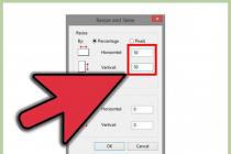
- If this is not possible, then change the type of flash drive from “removable media” to “hard disk” using the “BootIt Next Generation” utility, format it with the “HP USB Disk Storage Format Tool” utility and make it bootable again using “Windows USB/DVD Download Tool". You can download all these utilities below in the “Links” section.
- If the problem occurs after selecting the Windows installation partition, then use the tips for setting up the BIOS (sections 7-12). During installation, remove old partitions from the disk or do this using the Acronis Disk Director boot disk.
- If the installer reports that it cannot install Windows on the disk, then try running it or back.
Let me remind you that to exit the BIOS and save the settings, use the F10 key.
8. Links
In the following articles we will look at how to install, and.
Sandisk Cruzer
Transcend JetFlash 790 8Gb
Sandisk Cruzer
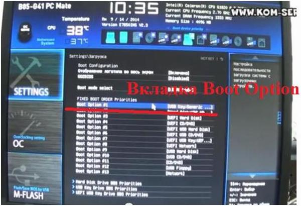
Let's look at ways to enter the BIOS of an MSI laptop motherboard using the B85-G41 model as an example to set WINDOWS 7 boot settings from a flash drive or CD/DVD drive.
We will be dealing with the new BIOS; the interface may seem unusual to those accustomed to the “old” BIOS options.
First of all, turn on the computer. When the screen saver appears, you must press the “Del” key on the laptop keyboard. It is located at the bottom of the digital section of the keyboard. Like everywhere else, it is on the right.
After pressing the “Del” key, the inscription “Entering the settings menu” will appear at the bottom left of the screen, then the MSI logo will appear and a little later we will find ourselves in the laptop’s BIOS.
The appearance of the new BIOS looks like this.

The advantages of this BIOS are that it already has a functioning mouse and has expanded functions.

To go to the BIOS settings, click on the “SETTINGS” tab. It is located at the top left.

In the Russian version, the “Download” tab is third in the list of five.
A new window will appear where you need to find the “Boot mode select” tab. Click on it, and in the window that pops up, select the “LEGACY + UEFI” item, if this item was not selected on your laptop earlier.
From the list of available devices for loading the operating system that pops up, select our flash drive by name USB + the name of your flash drive (the flash drive must be connected to one of the USB connectors of the laptop); if you need to boot the operating system from a disk, then select the CD/DVD item.
After these steps, press the F10 key. The laptop will ask if you want to save the configuration changes. Confirm by clicking “Yes”.
The second download option is a little faster.
The beginning is the same - entering the BIOS? SETTINGS? "Loading" ? "LEGACY+UEFI".
Reboot the laptop. When loading, press the F11 key. A prompt will appear. In this window, select a possible connected device from which we want to boot the operating system.
If you were looking for BIOS settings in pictures, then you have come to the right address.
The changes made will be protected by a lithium battery built into the motherboard and maintaining the required parameters in the event of a loss of voltage.
Thanks to the program, it is possible to establish stable interaction between the operating system (OS) and PC devices.
Attention! The present Boot network configuration section allows you to adjust parameters related to system boot speed and keyboard and mouse settings.
After finishing work or familiarizing yourself with the Bios Setup Utility menu, you need to press the hot Exit key, which automatically saves the changes made.
Section Main - Main Menu
Let's start working with the MAIN section, which is used to modify settings and adjust timing indicators.
Here you can independently configure the time and date of your computer, as well as configure connected hard drives and other storage devices.

To reformat the operating mode of the hard drive, you need to select the hard drive (for example: “SATA 1”, as shown in the figure).
- Type - This item indicates the type of connected hard drive;
- LBA Large Mode- is responsible for supporting drives with a capacity of more than 504 MB. So the recommended value here is AUTO.
- Block (Multi-Sector Transfer) - For faster operation here, we recommend selecting the AUTO mode;
- PIO Mode - Enables the hard drive to operate in legacy data exchange mode. It would also be best to select AUTO here;
- DMA Mode - gives direct memory access. To get faster read or write speed, select AUTO;
- Smart monitoring - this technology, based on an analysis of the drive’s operation, can warn of a possible disk failure in the near future;
- 32 bit Data Transfer - The option determines whether the 32-bit data exchange mode will be used by the standard IDE/SATA controller of the chipset.

Everywhere, using the “ENTER” key and arrows, the Auto mode is set. The exception is the 32 Bit Transfer subsection, which requires the Enabled setting to be fixed.
Important! It is required to refrain from changing the “Storage Configuration” option, which is located in the “System information” section and not to allow correction “SATADetectTimeout".

Advanced section - Additional settings
Now let's start setting up the basic PC components in the ADVANCED section, which consists of several sub-items.
Initially, you will need to set the necessary processor and memory parameters in the system configuration menu Jumper Free Configuration.

By selecting Jumper Free Configuration, you will be taken to the Configure System Frequency/Voltage subsection, where you can perform the following operations:
- automatic or manual overclocking of the hard drive - AI Overclocking;
- changing the clock frequency of memory modules - ;
- Memory Voltage;
- manual mode for setting chipset voltage - NB Voltage
- changing port addresses (COM,LPT) - Serial and Parallel Port;
- setting controller settings - Onboard Devices configuration.

Power Section - PC Power
The POWER item is responsible for powering the PC and contains several subsections that require the following settings:
- Suspended Mode- set automatic mode;
- ACPI APIC- set Enabled;
- ACPI 2.0- fix the Disabled mode.

BOOT section - boot management
Here you can determine the priority drive, choosing between a flash card, disk drive or hard drive.

If there are several hard drives, then in the Hard Disk sub-item the priority hard drive is selected.
The PC boot configuration is set in the Boot Setting subsection, which contains a menu consisting of several items:

Selecting a hard drive
The PC boot configuration is set in the Boot Setting subsection,

- Quick Boot– acceleration of OS loading;
- Logo Full Screen– disabling the screen saver and activating the information window containing information about the download process;
- Add On ROM- setting the order on the information screen of modules connected to the motherboard (MT) via slots;
- Wait For 'F1' If Error- activation of the function of forced pressing “F1” at the moment the system identifies an error.
The main task of the Boot section is to determine boot devices and set the required priorities.
- ASUS EZ Flash– using this option, you have the opportunity to update the BIOS from such drives as: floppy disk, Flash disk or CD.
- AINET– using this option, you can obtain information about the cable connected to the network controller.

Exit section - Exit and save
Particular attention should be paid to the EXIT item, which has 4 operating modes:
- Save Changes– save the changes made;
- Discard Changes + EXIT– leave the factory settings in effect;
- Setup Defaults– enter default parameters;
- Discard Changes– we cancel all our actions.

The following step-by-step instructions explain in detail the purpose of the main BIOS sections and the rules for making changes to improve PC performance.
Bios setup
Bios Settings - Detailed instructions in pictures
The functionality and interface of the BIOS receive any major changes quite rarely, so there is no need to update it regularly. However, if you have built a modern computer, but have an outdated version installed on the MSI motherboard, then it is recommended to think about upgrading it. The information below is only relevant for MSI motherboards.
Depending on how you decide to update, you will have to download either a special utility for Windows or the firmware files itself.
If you decide to update from the built-in BIOS utility or DOS line, then you will need an archive with installation files. In the case of a utility that runs under Windows, downloading installation files in advance may not be necessary, since the functionality of the utility allows you to download everything you need from MSI servers (depending on the selected type of installation).
It is recommended to use standard methods for installing BIOS updates - built-in utilities or a DOS line. Updating through the operating system interface is dangerous because if any bug occurs, there is a risk of suspending the process, which can lead to serious consequences, including PC failure.
Stage 1: Preparatory
If you decide to use standard methods, then you need to make appropriate preparations. First, you will need to find out information about the BIOS version, its developer and the model of your motherboard. All this is needed so that you can download the correct BIOS version for your PC and make a backup copy of the existing one.
To do this, you can use both built-in Windows tools and third-party software. In this case, the second option will be more convenient, so further step-by-step instructions are considered using the example of the AIDA64 program. It has a convenient interface in Russian and a large set of functions, but it is paid (although there is a demo period). The instructions look like this:

Now download all files for BIOS update from MSI official website using this guide:

To install using the standard method, you need to prepare a USB drive or CD/DVD in advance. Format the media to a file system FAT32 and transfer the BIOS installation files from the downloaded archive there. Make sure that among the files there are elements with extensions BIO And ROM. Without them, the update will not be possible.
Stage 2: Flashing
At this stage, we will consider the standard flashing method using the utility built into the BIOS. This method is good because it is suitable for all MSI devices and does not require any additional work other than those discussed above. Immediately after you have dumped all the files onto the flash drive, you can proceed directly to the update:

Method 2: Update from Windows
If you are not a very experienced PC user, you can try updating through a special utility for Windows. This method is only suitable for users of desktop computers with motherboards from MSI. If you have a laptop, then it is strongly recommended to refrain from this method, as it may cause problems with its operation. It is noteworthy that the utility is also suitable for creating a bootable USB flash drive for updating via a DOS line. However, the software is only suitable for updating via the Internet.
Instructions for using the MSI Live Update utility are as follows:

Method 3: Via DOS prompt
This method is somewhat confusing, as it involves creating a special bootable flash drive for DOS and working in this interface. It is strictly not recommended for inexperienced users to update using this method.
To create a flash drive with the update, you will need the MSI Live Update utility from the previous method. In this case, the program will also download all the necessary files from the official servers. The next steps are:
Now you will have to work in the DOS interface. To enter there and do everything correctly, it is recommended to use these step-by-step instructions:

Updating the BIOS on MSI computers/laptops is not that difficult, and there are a variety of methods provided here so you can choose the best option for yourself.